EP1750331A1 - Connexion enfichable électrique - Google Patents
Connexion enfichable électrique Download PDFInfo
- Publication number
- EP1750331A1 EP1750331A1 EP05015503A EP05015503A EP1750331A1 EP 1750331 A1 EP1750331 A1 EP 1750331A1 EP 05015503 A EP05015503 A EP 05015503A EP 05015503 A EP05015503 A EP 05015503A EP 1750331 A1 EP1750331 A1 EP 1750331A1
- Authority
- EP
- European Patent Office
- Prior art keywords
- plug
- union nut
- plug part
- mating
- mating connector
- Prior art date
- Legal status (The legal status is an assumption and is not a legal conclusion. Google has not performed a legal analysis and makes no representation as to the accuracy of the status listed.)
- Granted
Links
- 230000013011 mating Effects 0.000 claims abstract description 98
- 238000007789 sealing Methods 0.000 claims description 20
- 230000000295 complement effect Effects 0.000 description 4
- 238000004519 manufacturing process Methods 0.000 description 4
- 238000003780 insertion Methods 0.000 description 3
- 230000037431 insertion Effects 0.000 description 3
- 238000013024 troubleshooting Methods 0.000 description 2
- 238000013459 approach Methods 0.000 description 1
- 239000000969 carrier Substances 0.000 description 1
- 238000010276 construction Methods 0.000 description 1
- 230000001419 dependent effect Effects 0.000 description 1
- 230000000694 effects Effects 0.000 description 1
- 239000013013 elastic material Substances 0.000 description 1
- 238000005516 engineering process Methods 0.000 description 1
- 238000009434 installation Methods 0.000 description 1
- 239000011810 insulating material Substances 0.000 description 1
- 230000005405 multipole Effects 0.000 description 1
Images

Classifications
-
- H—ELECTRICITY
- H01—ELECTRIC ELEMENTS
- H01R—ELECTRICALLY-CONDUCTIVE CONNECTIONS; STRUCTURAL ASSOCIATIONS OF A PLURALITY OF MUTUALLY-INSULATED ELECTRICAL CONNECTING ELEMENTS; COUPLING DEVICES; CURRENT COLLECTORS
- H01R13/00—Details of coupling devices of the kinds covered by groups H01R12/70 or H01R24/00 - H01R33/00
- H01R13/62—Means for facilitating engagement or disengagement of coupling parts or for holding them in engagement
- H01R13/622—Screw-ring or screw-casing
-
- H—ELECTRICITY
- H01—ELECTRIC ELEMENTS
- H01R—ELECTRICALLY-CONDUCTIVE CONNECTIONS; STRUCTURAL ASSOCIATIONS OF A PLURALITY OF MUTUALLY-INSULATED ELECTRICAL CONNECTING ELEMENTS; COUPLING DEVICES; CURRENT COLLECTORS
- H01R13/00—Details of coupling devices of the kinds covered by groups H01R12/70 or H01R24/00 - H01R33/00
- H01R13/46—Bases; Cases
- H01R13/52—Dustproof, splashproof, drip-proof, waterproof, or flameproof cases
- H01R13/5202—Sealing means between parts of housing or between housing part and a wall, e.g. sealing rings
-
- H—ELECTRICITY
- H01—ELECTRIC ELEMENTS
- H01R—ELECTRICALLY-CONDUCTIVE CONNECTIONS; STRUCTURAL ASSOCIATIONS OF A PLURALITY OF MUTUALLY-INSULATED ELECTRICAL CONNECTING ELEMENTS; COUPLING DEVICES; CURRENT COLLECTORS
- H01R13/00—Details of coupling devices of the kinds covered by groups H01R12/70 or H01R24/00 - H01R33/00
- H01R13/46—Bases; Cases
- H01R13/52—Dustproof, splashproof, drip-proof, waterproof, or flameproof cases
- H01R13/5219—Sealing means between coupling parts, e.g. interfacial seal
Definitions
- the invention relates to an electrical plug connection, consisting of a plug part and a mating connector part, which can be plugged together and produce a plurality of electrical connections, wherein at least the plug part or the mating connector part carries on its body a screwed with the mating connector part or the plug part union nut, which is the connector protects against unintentional disconnection.
- connection technology is designed so that it securely connects the contact elements electrically to each other and protects with the connector coming into contact persons from dangerous voltages.
- connectors which consist of a multi-pin connector part with contact sockets and a multi-pole mating connector part with contact pins, which are designed so that they largely protect the electrical contact elements against mechanical and atmospheric influences.
- a disadvantage of these known connectors is the time required for screwing or unscrewing the nut during manufacture or when disconnecting the connector.
- Another disadvantage is that in a arranged between the faces of the male and mating connector sealing ring of the sealing ring is not always crushed so that it reliably seals the annular gap between the plug part and the mating connector part against the ingress of moisture. This is particularly the case when customary connector parts and mating connector parts of different manufacturers are used in pairs, since this often results in an easy game. This also causes a loosening of the nut by shaking movements.
- the invention is based on the object to improve a connector of the type mentioned in such a way that the disadvantages described above are reliably avoided; in particular, on the one hand, a release of the nut is reliably prevented by shaking and On the other hand, a quick installation with as few rotational movements can be done.
- the connector according to the invention has a union nut with two internal threads, wherein one of the two internal threads is provided for screwing with the plug part and the other internal thread for screwing with the mating connector part.
- the internal threads of the union nut are arranged opposite each other and extend to the end faces of the union nut. They are designed in opposite directions, and have an identical thread pitch.
- At least one of the two internal threads of the union nut is segmented.
- the segmented internal thread of the union nut has at least one thread-free region running in the direction of insertion, which is almost completely inserted into the complementary formed external thread of the associated male or mating connector part and the tightening of the screw on a rotation of the nut reduced by at most the thread-free area.
- Another advantage is the plug part and the mating connector part plugged together and the electrical connection can be made without screwing the connector. This can be helpful, for example, when commissioning and troubleshooting electrical devices and systems, if in the event of a fault, the plug connection must be quickly released and a faulty part replaced.
- an inventive plug part or mating connector part can be combined with the cap nut according to the invention with standard connectors of the same size and the same connection type, which ensures the connection to commercially available connectors.
- the segmented internal thread at the end faces of the nut facing side, on a first thread with a deviating from the threads of the external thread of the male or mating connector part cross-sectional profile.
- the first thread of the internal thread can not be brought into engagement with the thread of the external thread of the mating connector or plug part, which ensures that the connector part can only be screwed to the mating connector part when a contact carrier of the connector part is completely inserted into a threaded sleeve of the mating connector part is.
- the union nut is rotatably and slidably mounted on the body of the supporting plug or mating connector part.
- the nut is on the one hand secured against loss, on the other hand is a Plugging into a thread-free region of the thread of the supporting connector part possible, which has an advantageous effect on the assembly time in the production of the connector.
- To lock the nut must be rotated only by about a quarter to half turn, so that the threads of the thread engage in each other and make a screw.
- a development of the invention provides that the plug part and the mating plug part have at least partially axially aligned toothing profiles on their end faces.
- the tooth profiles are designed to be complementary and engage in screwing the connector into each other, they align the male part and the mating connector in the circumferential direction of the connector play each other.
- the profiles can be formed on corresponding end faces or lateral surfaces of the plug connection parts and, for example, have a sawtooth, trapezoidal or sinusoidal cross-section.
- the toothed profiles connect the plug part and the mating plug part form-fitting and force-locking with each other, whereby inadvertent rotation of the plug and the mating connector each other when tightening the nut is prevented and the electrical contact elements are protected from damage.
- the electrical contact elements in the male and the mating connector part are protected by seals from moisture.
- the plug nut or mating connector part carrying the union nut has a first sealing ring on the end face of the plug or mating connector part carrying the union nut and a second sealing ring in the region of the end faces of the union nut.
- the first sealing ring is radial when tightening the nut of the union nut squeezed and pressed against the body of the plug or the mating connector, he seals a first annular gap between the mating connector or plug part and the union nut of the connector in the assembled and bolted state of the connector.
- the second sealing ring is radially pressed when plugging or screwing the nut on the male or mating connector part; it seals a second annular gap between the plug or mating connector part and the union nut.
- the union nut of the electrical connector is secured against unintentional release, in particular by vibrations.
- a friction brake is provided on the nut carrying the union nut and / or the mating connector part, which inhibit a rotational movement of the union nut.
- the elastic sealing rings which radially seal the annular gaps between the plug part, the mating plug part and the nut.
- the sealing rings are pressed against the inner circumferential surface of the union nut positively and non-positively and fix the union nut by frictional force. To rotate the union nut, the frictional force between the friction brake and the union nut must be overcome.
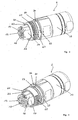
- the connector 1 according to the invention shown in Figure 1 consists essentially of a connector part 2, a mating connector part 3 and a union nut 4.
- the connector part 2 is plugged together with the mating connector part 3 and screwed by the worn from the plug part 2 union nut 4 with the mating connector part 3.
- the plug part 2 produces a plurality of electrical connections to the mating plug part 3, which is fastened to a machine housing, not shown.
- the plug part 2 and mating plug part 3 are shown individually in FIGS. 4 and 2, when not plugged together.
- the mating connector part 3 has a threaded sleeve 5 with an external thread 6.
- the external thread 6 has several threads and is executed segmented. It has three thread-free areas 34 in the insertion direction, which are arranged distributed asymmetrically over the circumference of the threaded sleeve 5.
- an equivalent adapted internal thread 7 of the union nut 4 as shown in Figure 5, are almost completely inserted.
- a stop 37 is provided for the nut 4.
- a contact carrier 8 is recessed from an insulating material. He is fixed with radial play in the threaded sleeve 5.
- the contact carrier 8 has as electrical contact elements five contact pins 9 for contacting trained as contact sockets 10 contact elements of the connector part 2.
- the contact pins 9 extend Up to the end face 11 of the threaded sleeve 5.
- alignment means 12 are provided which engage in the corresponding insertion of the connector 1 in the corresponding alignment means 13 of a contact carrier 14 of the connector part 2.
- the alignment means 12, 13 align the contact carriers 8, 14 in the radial direction in alignment with one another.
- the alignment means 12, 13 are designed so that they are not hindering when plugging the connector part 2 or the mating connector part 3 with commercially available connectors.
- a tooth profile 15 is designed to prevent rotation of the plug part 2.
- the tooth profile 15 is aligned axially and consists of a plurality of trapezoidal recesses 16 in the end face 11.
- the recesses 16 are uniformly distributed over an annular region of the end face 11.
- a web 17 is arranged in the axial direction, which forms a reverse polarity protection for the electrical connections of the connector 1 in conjunction with an axially extending groove 18 of the contact carrier 14 of the plug part 2.
- Figures 3, 4 show the plug part 2, which is frontally complementary to the mating connector part 3.
- the contact carrier 14 projects in the axial direction over the body 19 of the plug part 2 and can be inserted into the threaded bush 5 of the mating plug part 3. He has five contact sockets 10 which contact the contact pins 9 of the mating connector part 3 in the inserted state of the connector part 2.
- the body 19 of the plug part 2 has on its side facing the mating plug part 3, an external thread 20 for screwing with the union nut 4.
- the external thread 20 can be formed as a full thread (shown in FIG. 3) or as a segmented thread (shown in FIG. 4). If the external thread 20 is designed as a full thread, the union nut is screwed by several turns with the plug part 2. Is the external thread 20 similar to the external thread 6 of the mating connector part. 3 designed, the union nut 4 can be plugged onto the external thread 20. The tightening of the nut 4 is reduced to about a quarter turn.
- An end face 21 of the plug part 2 lies opposite the end face 11 of the mating plug part 3.
- the end face 21 carries in an inner annular surface a tooth profile 22 which is complementary to the tooth profile 15 of the threaded bushing 5 of the mating connector part 3.
- Projections 23 of the toothed profile 22 engage in plugged and screwed connector 1 together in the recesses 16 of the tooth profile 15 and prevent twisting of the plug part 2 relative to the mating connector part 3.
- the end face 21 is flat and smooth in an outer annular surface.
- a first elastic sealing ring 25 for sealing a first annular gap 36 between the threaded sleeve 5 of the mating connector part 3 and the union nut 4 is arranged.
- the sealing ring 25 is squeezed when tightening the nut 4 and pressed against the outside of the threaded sleeve 5 of the mating connector part 3 and the union nut 4 of the connector part 2.
- the sealing ring 25 seals the annular gap 36 of the connector 1 in the screwed state of the connector from radially.
- the cap nut 2 carrying the union nut 2 has a second elastic sealing ring 26, which is arranged on the side remote from the end face 21 of the plug part 2 end of the external thread 20 of the plug part 2.
- the O-ring 26 is located in an annular groove 27 of the body 19 of the connector part 2 a. It seals a second annular gap 39 between the union nut 4 and the body 19 of the plug part 2 in the region of the end face 31 of the union nut 4 radially.
- sealing rings 25, 26 O-rings are provided, which are made of an elastic material having rubber-like properties and a high Have friction coefficients.
- the O-rings 25, 26 are pressed against the union nut 4 and act as a friction brake between the plug part 2, the mating connector part 3 and the union nut 4. They inhibit a rotation of the union nut 4 by their frictional forces and prevent the union nut 4 by vibrations solves.
- the O-rings 25, 26 protect with screwed connector 1, the contact pins 9 of the mating connector part 3 and the contact sockets 10 of the connector part 2 from moisture.
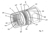
- Figure 5 shows the mating connector part 3 facing the end of the plug part 2 with a screwed with the plug part 2 union nut 4.
- the external thread 20 of the plug part 2 is formed as a full thread; It is connected to the plug-side internal thread 28 of the union nut 4 in engagement.
- the internal thread 28 can be configured as a full thread or as a segmented thread, since both embodiments of the internal thread 28 can be combined with the external thread 20 of the plug part 2 designed as a full thread.
- a latch 30 is formed, which engages in a guide, not shown, the union nut 4 and the union nut 4 rotatably locked to the connector part 2.
- the latching 30 protects the plug part 2 against loss of the union nut 4.
- the latching 30 is effective when the end face 31 of the union nut 4 is removed only in about a quarter to full turn of the stopper 32 of the connector part 2. After snapping the catch 30, the union nut 4 can only be tightened or loosened by about a quarter to full turn.
- the mating connector part 3 facing internal thread 7 of the union nut 4 is executed segmented. It is equivalent to the segmented external thread 6 of the threaded bushing 5 is formed.
- the internal thread 7 of the union nut 4 has recesses 33, with which it can be plugged onto the external thread 6 of the mating connector part 3. Accordingly, engage over the recesses 34 of the external thread 6 of the mating connector part 3, not shown in the figure 5, the internal thread 7 of the union nut 4 on the mating connector part 3 side facing.
- a first thread 40 of the internal thread 7 of the union nut 4 has a different from the external thread 6 of the threaded sleeve 5 of the mating connector part 3 cross-sectional profile.
- the thread 40 of the internal thread 7 can not be brought into engagement with the threads of the external thread 6, which ensures that the plug part 2 can only be screwed to the mating plug part 3, when the contact carrier 14 of the plug part 2 completely into the threaded sleeve 5 of the mating connector part 3 is introduced.
Landscapes
- Details Of Connecting Devices For Male And Female Coupling (AREA)
- Connector Housings Or Holding Contact Members (AREA)
Priority Applications (5)
| Application Number | Priority Date | Filing Date | Title |
|---|---|---|---|
| EP05015503A EP1750331B1 (fr) | 2005-07-16 | 2005-07-16 | Connexion enfichable électrique |
| DE502005001198T DE502005001198D1 (de) | 2005-07-16 | 2005-07-16 | Elektrische Steckverbindung |
| ES05015503T ES2292021T3 (es) | 2005-07-16 | 2005-07-16 | Conexion enchufable electrica. |
| JP2006190092A JP4288274B2 (ja) | 2005-07-16 | 2006-07-11 | 差込式コネクター |
| US11/488,410 US7331807B2 (en) | 2005-07-16 | 2006-07-17 | Electrical plug-in connection |
Applications Claiming Priority (1)
| Application Number | Priority Date | Filing Date | Title |
|---|---|---|---|
| EP05015503A EP1750331B1 (fr) | 2005-07-16 | 2005-07-16 | Connexion enfichable électrique |
Publications (2)
| Publication Number | Publication Date |
|---|---|
| EP1750331A1 true EP1750331A1 (fr) | 2007-02-07 |
| EP1750331B1 EP1750331B1 (fr) | 2007-08-08 |
Family
ID=35447564
Family Applications (1)
| Application Number | Title | Priority Date | Filing Date |
|---|---|---|---|
| EP05015503A Expired - Lifetime EP1750331B1 (fr) | 2005-07-16 | 2005-07-16 | Connexion enfichable électrique |
Country Status (5)
| Country | Link |
|---|---|
| US (1) | US7331807B2 (fr) |
| EP (1) | EP1750331B1 (fr) |
| JP (1) | JP4288274B2 (fr) |
| DE (1) | DE502005001198D1 (fr) |
| ES (1) | ES2292021T3 (fr) |
Cited By (1)
| Publication number | Priority date | Publication date | Assignee | Title |
|---|---|---|---|---|
| DE102006017983B4 (de) * | 2006-04-13 | 2011-06-01 | Phoenix Contact Gmbh & Co. Kg | Elektrische Steckverbindung |
Families Citing this family (12)
| Publication number | Priority date | Publication date | Assignee | Title |
|---|---|---|---|---|
| FR2925234B1 (fr) * | 2007-12-14 | 2010-01-22 | Radiall Sa | Connecteur a systeme anti-deverrouillage |
| JP5312175B2 (ja) * | 2009-04-24 | 2013-10-09 | 第一電子工業株式会社 | コネクタ |
| EP2468013B1 (fr) | 2009-08-17 | 2014-01-08 | Phonak AG | Fixation d'un crochet à un dispositif auditif |
| JP5449033B2 (ja) * | 2010-05-28 | 2014-03-19 | アズビル株式会社 | コネクタ |
| DE102014116322B3 (de) * | 2014-11-10 | 2015-08-13 | Lumberg Connect Gmbh | Steckverbinder mit Vibrationssicherung |
| CN107863638B (zh) * | 2017-10-25 | 2019-03-26 | 安徽江淮汽车集团股份有限公司 | 一种汽车插件 |
| MX2021002297A (es) | 2018-08-29 | 2021-04-28 | Leviton Manufacturing Co | Dispositivos de clavija y manga. |
| US11515665B2 (en) | 2018-10-08 | 2022-11-29 | Leviton Manufacturing Co., Inc. | Pin and sleeve device with features to facilitate easier assembly |
| USD924143S1 (en) * | 2018-10-29 | 2021-07-06 | Phoenix Contact Gmbh & Co. Kg | Electrical connection plug |
| EP3949032A1 (fr) * | 2019-04-01 | 2022-02-09 | Pflitsch GmbH & Co. KG. | Système de vissage de fiche |
| EP3993178B1 (fr) * | 2020-10-27 | 2024-01-24 | TE Connectivity Industrial GmbH | Prise électrique avec dispositif de freinage à friction, ainsi qu'agencement et procédé |
| CN113451799A (zh) * | 2021-06-21 | 2021-09-28 | 江苏安诺生电子股份有限公司 | 适用于5g通讯中继器的快插多芯集成连接器 |
Citations (7)
| Publication number | Priority date | Publication date | Assignee | Title |
|---|---|---|---|---|
| US5435760A (en) * | 1993-08-27 | 1995-07-25 | Sunbank Electronics, Inc. | Self-seating connector adapter |
| US5439386A (en) * | 1994-06-08 | 1995-08-08 | Augat Inc. | Quick disconnect environmentally sealed RF connector for hardline coaxial cable |
| GB2314391A (en) * | 1996-06-20 | 1997-12-24 | B D Kendle Engineering Ltd | High strength quick connector for tools |
| DE19904037A1 (de) * | 1999-02-02 | 2000-08-03 | Peter Westerfeld | Steckverbindung in explosionsgeschützter Ausführung |
| US6135800A (en) * | 1998-12-22 | 2000-10-24 | Conxall Corporation | Anti-rotational electrical connector |
| US20040207202A1 (en) * | 2003-04-17 | 2004-10-21 | Parks William C. | Breech lock connector for a subsea riser |
| EP1524732A1 (fr) * | 2003-10-18 | 2005-04-20 | Phoenix Contact GmbH & Co. KG | Connecteur électrique |
Family Cites Families (6)
| Publication number | Priority date | Publication date | Assignee | Title |
|---|---|---|---|---|
| US2961630A (en) * | 1959-10-05 | 1960-11-22 | Cannon Electric Co | Self-locking coupling device |
| US3994552A (en) * | 1975-10-01 | 1976-11-30 | International Telephone And Telegraph Corporation | Submersible pipe electrical cable assembly |
| US5066905A (en) * | 1988-11-14 | 1991-11-19 | Baton Labs, Inc. | Battery cable assembly with in-line switch |
| US5827078A (en) * | 1996-12-20 | 1998-10-27 | Simonian; Christopher L. | Connector accessories, electrical, backshell, grounding, flex cables |
| CA2449182C (fr) * | 2003-11-12 | 2008-02-26 | Phoenix Contact Gmbh & Co. Kg | Connecteur electrique |
| US7207820B1 (en) * | 2006-02-03 | 2007-04-24 | John Mezzalingua Associates, Inc. | Connecting assembly for a cable and method of connecting a cable |
-
2005
- 2005-07-16 EP EP05015503A patent/EP1750331B1/fr not_active Expired - Lifetime
- 2005-07-16 DE DE502005001198T patent/DE502005001198D1/de not_active Expired - Lifetime
- 2005-07-16 ES ES05015503T patent/ES2292021T3/es not_active Expired - Lifetime
-
2006
- 2006-07-11 JP JP2006190092A patent/JP4288274B2/ja not_active Expired - Fee Related
- 2006-07-17 US US11/488,410 patent/US7331807B2/en not_active Expired - Fee Related
Patent Citations (7)
| Publication number | Priority date | Publication date | Assignee | Title |
|---|---|---|---|---|
| US5435760A (en) * | 1993-08-27 | 1995-07-25 | Sunbank Electronics, Inc. | Self-seating connector adapter |
| US5439386A (en) * | 1994-06-08 | 1995-08-08 | Augat Inc. | Quick disconnect environmentally sealed RF connector for hardline coaxial cable |
| GB2314391A (en) * | 1996-06-20 | 1997-12-24 | B D Kendle Engineering Ltd | High strength quick connector for tools |
| US6135800A (en) * | 1998-12-22 | 2000-10-24 | Conxall Corporation | Anti-rotational electrical connector |
| DE19904037A1 (de) * | 1999-02-02 | 2000-08-03 | Peter Westerfeld | Steckverbindung in explosionsgeschützter Ausführung |
| US20040207202A1 (en) * | 2003-04-17 | 2004-10-21 | Parks William C. | Breech lock connector for a subsea riser |
| EP1524732A1 (fr) * | 2003-10-18 | 2005-04-20 | Phoenix Contact GmbH & Co. KG | Connecteur électrique |
Cited By (1)
| Publication number | Priority date | Publication date | Assignee | Title |
|---|---|---|---|---|
| DE102006017983B4 (de) * | 2006-04-13 | 2011-06-01 | Phoenix Contact Gmbh & Co. Kg | Elektrische Steckverbindung |
Also Published As
| Publication number | Publication date |
|---|---|
| EP1750331B1 (fr) | 2007-08-08 |
| JP4288274B2 (ja) | 2009-07-01 |
| ES2292021T3 (es) | 2008-03-01 |
| JP2007027112A (ja) | 2007-02-01 |
| US7331807B2 (en) | 2008-02-19 |
| US20070037429A1 (en) | 2007-02-15 |
| DE502005001198D1 (de) | 2007-09-20 |
Similar Documents
| Publication | Publication Date | Title |
|---|---|---|
| DE2822365C2 (fr) | ||
| EP2962366B1 (fr) | Connecteur électrique industriel | |
| DE3787068T2 (de) | Feuchtigkeitssichere Abdichtung für Koaxialverbinder. | |
| EP1750331B1 (fr) | Connexion enfichable électrique | |
| DE3218677C2 (de) | Elektrische Steckverbinderanordnung | |
| EP2625751B1 (fr) | Connecteur de fils electrique | |
| EP1901402A1 (fr) | Connecteur solaire doté de moyens d'encliquetage améliorés | |
| EP2754211A1 (fr) | Connecteur à contacts protégés | |
| EP3396785A1 (fr) | Système de connecteur | |
| EP4066325A1 (fr) | Appareil de verrouillage secondaire | |
| EP1362393A1 (fr) | Connecteur enfichable comportant un boitier et un insert de verrouillage | |
| EP1710886A1 (fr) | Traversée de câble | |
| DE10233075B4 (de) | Elektrischer Steckverbinder | |
| WO2015104117A1 (fr) | Dispositif de fixation d'un conducteur électrique dans un connecteur, connecteur pour conducteur électrique, ainsi que câble électrique | |
| DE4301504C2 (de) | Elektrischer Steckverbinder | |
| EP2115825B1 (fr) | Connecteur électrique à fiches | |
| EP1289073A1 (fr) | Connecteur électrique | |
| EP1641086B1 (fr) | Connecteur coaxial | |
| DE202007017488U1 (de) | Steckeranordnung | |
| EP1524732B1 (fr) | Connecteur électrique | |
| DE202005010113U1 (de) | Steckverbinderkupplung | |
| DE3909548C2 (fr) | ||
| DE102007049677A1 (de) | Schnellverschraubbare elektrische Steckverbindung | |
| DE102014108283B4 (de) | Stecker | |
| BE1027769B1 (de) | Kabelverschraubungssystem |
Legal Events
| Date | Code | Title | Description |
|---|---|---|---|
| PUAI | Public reference made under article 153(3) epc to a published international application that has entered the european phase |
Free format text: ORIGINAL CODE: 0009012 |
|
| 17P | Request for examination filed |
Effective date: 20060302 |
|
| AK | Designated contracting states |
Kind code of ref document: A1 Designated state(s): AT BE BG CH CY CZ DE DK EE ES FI FR GB GR HU IE IS IT LI LT LU LV MC NL PL PT RO SE SI SK TR |
|
| AX | Request for extension of the european patent |
Extension state: AL BA HR MK YU |
|
| GRAP | Despatch of communication of intention to grant a patent |
Free format text: ORIGINAL CODE: EPIDOSNIGR1 |
|
| GRAS | Grant fee paid |
Free format text: ORIGINAL CODE: EPIDOSNIGR3 |
|
| GRAA | (expected) grant |
Free format text: ORIGINAL CODE: 0009210 |
|
| AK | Designated contracting states |
Kind code of ref document: B1 Designated state(s): CH DE ES FR GB IT LI |
|
| REG | Reference to a national code |
Ref country code: GB Ref legal event code: FG4D Free format text: NOT ENGLISH |
|
| REG | Reference to a national code |
Ref country code: CH Ref legal event code: EP |
|
| REF | Corresponds to: |
Ref document number: 502005001198 Country of ref document: DE Date of ref document: 20070920 Kind code of ref document: P |
|
| AKX | Designation fees paid |
Designated state(s): CH DE ES FR GB IT LI |
|
| GBT | Gb: translation of ep patent filed (gb section 77(6)(a)/1977) |
Effective date: 20070920 |
|
| REG | Reference to a national code |
Ref country code: CH Ref legal event code: NV Representative=s name: ABACUS PATENTANWAELTE KLOCKE SPAETH BARTH |
|
| REG | Reference to a national code |
Ref country code: ES Ref legal event code: FG2A Ref document number: 2292021 Country of ref document: ES Kind code of ref document: T3 |
|
| ET | Fr: translation filed | ||
| PLBE | No opposition filed within time limit |
Free format text: ORIGINAL CODE: 0009261 |
|
| STAA | Information on the status of an ep patent application or granted ep patent |
Free format text: STATUS: NO OPPOSITION FILED WITHIN TIME LIMIT |
|
| 26N | No opposition filed |
Effective date: 20080509 |
|
| PGFP | Annual fee paid to national office [announced via postgrant information from national office to epo] |
Ref country code: ES Payment date: 20080821 Year of fee payment: 4 |
|
| PGFP | Annual fee paid to national office [announced via postgrant information from national office to epo] |
Ref country code: FR Payment date: 20080718 Year of fee payment: 4 |
|
| REG | Reference to a national code |
Ref country code: CH Ref legal event code: PL |
|
| GBPC | Gb: european patent ceased through non-payment of renewal fee |
Effective date: 20090716 |
|
| REG | Reference to a national code |
Ref country code: FR Ref legal event code: ST Effective date: 20100331 |
|
| PG25 | Lapsed in a contracting state [announced via postgrant information from national office to epo] |
Ref country code: FR Free format text: LAPSE BECAUSE OF NON-PAYMENT OF DUE FEES Effective date: 20090731 Ref country code: LI Free format text: LAPSE BECAUSE OF NON-PAYMENT OF DUE FEES Effective date: 20090731 Ref country code: CH Free format text: LAPSE BECAUSE OF NON-PAYMENT OF DUE FEES Effective date: 20090731 |
|
| PG25 | Lapsed in a contracting state [announced via postgrant information from national office to epo] |
Ref country code: GB Free format text: LAPSE BECAUSE OF NON-PAYMENT OF DUE FEES Effective date: 20090716 |
|
| REG | Reference to a national code |
Ref country code: ES Ref legal event code: FD2A Effective date: 20090717 |
|
| PG25 | Lapsed in a contracting state [announced via postgrant information from national office to epo] |
Ref country code: ES Free format text: LAPSE BECAUSE OF NON-PAYMENT OF DUE FEES Effective date: 20090717 |
|
| PGFP | Annual fee paid to national office [announced via postgrant information from national office to epo] |
Ref country code: IT Payment date: 20080731 Year of fee payment: 4 |
|
| PGFP | Annual fee paid to national office [announced via postgrant information from national office to epo] |
Ref country code: DE Payment date: 20130731 Year of fee payment: 9 |
|
| REG | Reference to a national code |
Ref country code: DE Ref legal event code: R082 Ref document number: 502005001198 Country of ref document: DE Representative=s name: ABACUS PATENTANWAELTE, DE |
|
| REG | Reference to a national code |
Ref country code: DE Ref legal event code: R119 Ref document number: 502005001198 Country of ref document: DE |
|
| PG25 | Lapsed in a contracting state [announced via postgrant information from national office to epo] |
Ref country code: DE Free format text: LAPSE BECAUSE OF NON-PAYMENT OF DUE FEES Effective date: 20150203 |
|
| REG | Reference to a national code |
Ref country code: DE Ref legal event code: R119 Ref document number: 502005001198 Country of ref document: DE Effective date: 20150203 |