EP1750362A2 - Alimentation de puissance courant continu pour climatiseur - Google Patents
Alimentation de puissance courant continu pour climatiseur Download PDFInfo
- Publication number
- EP1750362A2 EP1750362A2 EP06116278A EP06116278A EP1750362A2 EP 1750362 A2 EP1750362 A2 EP 1750362A2 EP 06116278 A EP06116278 A EP 06116278A EP 06116278 A EP06116278 A EP 06116278A EP 1750362 A2 EP1750362 A2 EP 1750362A2
- Authority
- EP
- European Patent Office
- Prior art keywords
- voltage
- power supply
- air conditioner
- supply device
- target voltage
- Prior art date
- Legal status (The legal status is an assumption and is not a legal conclusion. Google has not performed a legal analysis and makes no representation as to the accuracy of the status listed.)
- Granted
Links
Images


Classifications
-
- H—ELECTRICITY
- H02—GENERATION; CONVERSION OR DISTRIBUTION OF ELECTRIC POWER
- H02M—APPARATUS FOR CONVERSION BETWEEN AC AND AC, BETWEEN AC AND DC, OR BETWEEN DC AND DC, AND FOR USE WITH MAINS OR SIMILAR POWER SUPPLY SYSTEMS; CONVERSION OF DC OR AC INPUT POWER INTO SURGE OUTPUT POWER; CONTROL OR REGULATION THEREOF
- H02M7/00—Conversion of AC power input into DC power output; Conversion of DC power input into AC power output
- H02M7/02—Conversion of AC power input into DC power output without possibility of reversal
- H02M7/04—Conversion of AC power input into DC power output without possibility of reversal by static converters
- H02M7/12—Conversion of AC power input into DC power output without possibility of reversal by static converters using discharge tubes with control electrode or semiconductor devices with control electrode
- H02M7/21—Conversion of AC power input into DC power output without possibility of reversal by static converters using discharge tubes with control electrode or semiconductor devices with control electrode using devices of a triode or transistor type requiring continuous application of a control signal
- H02M7/217—Conversion of AC power input into DC power output without possibility of reversal by static converters using discharge tubes with control electrode or semiconductor devices with control electrode using devices of a triode or transistor type requiring continuous application of a control signal using semiconductor devices only
-
- H—ELECTRICITY
- H02—GENERATION; CONVERSION OR DISTRIBUTION OF ELECTRIC POWER
- H02M—APPARATUS FOR CONVERSION BETWEEN AC AND AC, BETWEEN AC AND DC, OR BETWEEN DC AND DC, AND FOR USE WITH MAINS OR SIMILAR POWER SUPPLY SYSTEMS; CONVERSION OF DC OR AC INPUT POWER INTO SURGE OUTPUT POWER; CONTROL OR REGULATION THEREOF
- H02M1/00—Details of apparatus for conversion
- H02M1/10—Arrangements incorporating converting means for enabling loads to be operated at will from different kinds of power supplies, e.g. from AC or DC
Definitions
- the present invention relates to technology for converting an AC voltage from an AC power supply to a predetermined DC voltage that is supplied to a load, and relates more particularly to technology for a DC power supply device for an air conditioner.
- Japanese Unexamined Patent Appl. Pub. 2004-72806 teaches a DC power supply device for converting voltage from an AC power supply to a DC voltage supplied to a load where the DC power supply device detects the zero cross of the AC power supply and improves the power factor to produce a high DC output voltage by inserting a reactor to short the AC power supply for a predetermined time near the zero cross of the AC power supply.
- FIG. 5 is a schematic diagram of the conventional DC power supply device described in Japanese Unexamined Patent Appl. Pub. 2004-72806 .
- the conventional DC power supply device shown in FIG. 5 is feedback controlled to maintain the DC voltage equal to a predetermined target voltage, therefore holds the DC voltage required to drive the compressor 9p substantially constant even when the supply voltage from the AC power supply 1p fluctuates, and therefore affords an extremely stable system.
- the conventional DC power supply device of the type shown in FIG. 5 suffers from increased loss in the shorting unit 3p as the target voltage setting rises, and the temperature of the shorting unit 3p therefore rises. More particularly, when the supply voltage of the AC power supply 1p drops in a DC power supply device that uses feedback control based on the DC voltage, the shorting time of the shorting unit 3p increases in order to pull the DC voltage up to the target voltage, and the shorting unit 3p therefore tends to be subject to an extreme increase in temperature.
- the highest target voltage that can be set is limited by the maximum operating temperature of the DC power supply device.
- the DC voltage In an air conditioner that can be used for both heating and cooling, the DC voltage must therefore be set to allow for operation in the air conditioning mode when the outdoor temperature is high.
- the outdoor temperature is lower when the air conditioner is used for heating than when it is used for cooling.
- the induction voltage of a compressor motor that uses a common magnet made of rare earth or ferrite materials tends to increase as the temperature decreases. Assuming the compressor is driven at the same speed, the compressor therefore requires a higher DC voltage during cooling mode operation.
- a problem with the DC power supply device for a conventional air conditioner in which the threshold value is determined by the compressor speed and input current is that the temperature increase in the DC power supply device during cooling mode operation limits the voltage boosting performance of the DC power supply device in the heating mode, that is, limits the high speed performance of the compressor.
- an object of the present invention is to provide a DC power supply device for an air conditioner that can maximally supply the DC voltage required to drive the compressor at the speed required by the heating or cooling operating mode of the air conditioner.
- a DC power supply device for an air conditioner has a direct current supply means for converting an AC voltage from an AC power supply to a predetermined DC voltage and supplying the DC voltage to a load of the air conditioner; and a control means for controlling the DC supply means based on a comparison of the DC voltage and a predetermined target voltage.
- the target voltage is set to a level greater than or equal to the target voltage that is set when operating in a cooling mode.
- a DC power supply device for an air conditioner has a direct current supply means for converting an AC voltage from an AC power supply to a predetermined DC voltage and supplying the DC voltage to a load of the air conditioner; a control means for controlling the DC supply means based on a comparison of the DC voltage and a predetermined target voltage; and a temperature detection means (14) for detecting an ambient temperature; wherein the target voltage increases as the ambient temperature decreases.
- the DC power supply device for an air conditioner affords greater tolerance for the DC power supply device temperature to increase when operating in the cooling mode when the outdoor temperature is high.
- the voltage boosting performance can be extracted to the maximum temperature limit of the shorting element while also allowing for an increase in the induction voltage of the compressor motor.
- the effect of the invention is particularly pronounced when the induction voltage of the motor rises and it is necessary to drive the motor at a high DC voltage as a result of wrapping the compressor motor for energy conservation.
- the DC power supply device for an air conditioner that rectifies the AC voltage from an AC power supply to a predetermined DC voltage supplied to a load
- the DC power supply device can be used to the maximum operating temperature of the DC power supply device in the heating mode, and the maximum compressor speed in the heating mode can be increased, by applying feedback control so that the DC voltage is equal to a target voltage that is predetermined based on the speed of the compressor and the operating mode of the air conditioner, and setting the target voltage for heating mode operation higher than the target voltage for cooling mode operation.
- the DC power supply device can extract maximum high speed efficiency according to the operating environment of the air conditioner by applying feedback control so that the DC voltage is equal to a target voltage that is predetermined based on the speed of the compressor and the ambient temperature, and increasing the target voltage setting as the ambient temperature of the DC power supply device decreases.
- FIG. 1 is a schematic diagram of a DC power supply device according to a first embodiment of the invention.
- a DC power supply device according to this embodiment of the invention has a reactor 2 that has one end connected to the AC power supply 1 and inductively charges and discharges the AC voltage from the AC power supply 1, a rectification circuit 4 that is connected to the other end of the reactor 2 and rectifies the output voltage of the reactor 2, a smoothing capacitor 12 that is connected to both DC output nodes of the rectification circuit 4 for generating a DC voltage from the rectified voltage, a shorting unit 3 and capacitor 13 that are connected between the other end of the reactor 2 and the negative output node of the rectification circuit 4, a zero cross detection circuit 7 for detecting the zero cross of the AC voltage from the AC power supply 1, and a control unit 8 for controlling the shorting unit 3.
- This DC power supply device supplies the resulting DC voltage to a load 11 comprising a compressor 9 (compressor drive motor 9), and an inverter circuit 10 for driving the compressor 9.
- the reactor 2, rectification circuit 4, smoothing capacitor 12, and shorting unit 3 constitute the DC supply unit.
- the DC voltages from both ends of the smoothing capacitor 12 are input to the control unit 8, which generates a drive signal for driving the shorting unit 3 triggered by the zero cross detected by the zero cross detection circuit 7, and shorts and opens the shorting unit 3 at least once every half cycle of the power supply.
- the control unit 8 determines the target voltage of the DC power supply device from the speed of the compressor 9 and the outdoor temperature detected by a temperature detection unit 14 disposed in the air conditioner, and applies feedback control adjusting the shorting frequency, shorting time, and shorting position of the shorting unit 3 so that the DC voltage supplied to the inverter circuit 10 is held at a predetermined voltage (target voltage). More specifically, the control unit 8 compares the DC voltage and the predetermined target voltage to control the DC supply unit, and more particularly the shorting unit 3.
- FIG. 2 describes the relationship between compressor speed and the target voltage in the DC power supply device for an air conditioner according to this first embodiment of the invention.
- the target voltages are preset and stored in memory. These target voltages are determined as a function of the compressor 9 speed and the outdoor temperature.
- the target voltage is set to a voltage Va on the line denoted La in FIG. 2.
- the target voltage is set to a voltage Vb on the line denoted Lb in FIG. 2.
- the target voltage is set to a voltage Vc on the line denoted Lc in FIG. 2.
- the outdoor temperature corresponds to the ambient temperature of the outdoor unit (not shown in the figure) of the air conditioner or the ambient temperature of the DC power supply device.
- Air conditioners are generally used over a wide range of temperatures from below freezing to over 40 degC. Because the tolerance for a temperature increase in the DC power supply device rises as the ambient temperature falls, the voltage boosting performance of the DC power supply device can always be used to maximum efficiency according to the operating conditions of the air conditioner assuming the same operating mode and same compressor 9 speed by setting the target voltage higher as the ambient temperature (outdoor temperature) drops.
- the target voltage of the DC power supply device is set to a constant voltage V0 irrespective of the outdoor temperature.
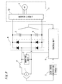
- FIG. 3 is a schematic diagram of a DC power supply device according to a second embodiment of the invention.
- a DC power supply device according to this embodiment of the invention has a reactor 2 that has one end connected to the AC power supply 1 and inductively charges and discharges the AC voltage from the AC power supply 1, a shorting unit 3 for shorting the AC power supply 1 through the reactor 2, a rectification circuit 4 that is connected to the other end of the reactor 2 and rectifies the output voltage of the reactor 2, a capacitor 5 and a capacitor 6 connected in series between the DC output nodes of the rectification circuit 4 for generating a DC voltage from the rectified voltage, a zero cross detection circuit 7 for detecting the zero cross of the AC voltage from the AC power supply 1, and a control unit 8 for controlling the shorting unit 3.
- This DC power supply device supplies the resulting DC voltage to a load 11 comprising a compressor 9 (compressor drive motor 9), and an inverter circuit 10 for driving the compressor 9.
- the reactor 2, rectification circuit 4, capacitor 5, capacitor 6, and shorting unit 3 constitute the DC supply unit.
- the control unit 8 is a microcomputer, for example, that takes the DC voltage input between the positive side of capacitor 5 and the negative side of capacitor 6, generates a drive signal for driving the shorting unit 3 triggered by the zero cross detected by the zero cross detection circuit 7, and shorts and opens the shorting unit 3 at least once every half cycle of the power supply.
- the control unit 8 determines the target voltage of the DC power supply device from the speed of the compressor 9 and the operating mode (state) of the air conditioner, and applies feedback control adjusting the shorting frequency, shorting time, and shorting position of the shorting unit 3 so that the DC voltage supplied to the inverter circuit 10 is held at a predetermined voltage (target voltage). More specifically, the control unit 8 compares the DC voltage and the predetermined target voltage to control the DC supply unit, and more particularly the shorting unit 3.
- FIG. 4 describes the relationship between compressor speed and the target voltage in the DC power supply device for an air conditioner according to this second embodiment of the invention.
- the target voltage of the DC power supply device differs according to the operating mode (state) of the air conditioner, that is, whether the air conditioner is in the cooling mode or the heating mode.
- the operating mode state
- voltage V1 on line L1 in FIG. 4 is set as the target voltage when operating in the cooling mode
- voltage V2 on line L2 (> L1) in FIG. 4 is set as the target voltage when operating in the heating mode.
- the expected outdoor temperature is lower than when operating in the cooling mode, there is more tolerance for the DC power supply device temperature to increase than when in the cooling mode, and the target voltage used in the heating mode can therefore be set higher in accordance with this temperature difference.
- the induction voltage of a compressor motor that uses a common magnet made of rare earth or ferrite materials tends to increase as the temperature decreases.
- a DC power supply device that can minimize the temperature increase in the shorting unit 3, for example, while maintaining the minimum DC voltage required to drive the compressor 9 can be provided by setting the target voltage higher in the heating mode than in the cooling mode assuming a constant compressor 9 speed.
- the DC voltage required by the load conditions of the air conditioner can always be supplied to the load 11 by setting the target voltage of the DC power supply device higher as the ambient temperature decreases.
- the target voltage is selected according to the compressor 9 speed and operating mode of the air conditioner in this second embodiment of the invention, but the same effect can be achieved by using the input current from the AC power supply 1 or the motor current of the compressor 9 instead of the speed of the compressor 9.
- the DC power supply device for an air conditioner affords greater tolerance for the DC power supply device temperature to increase when operating in the cooling mode when the outdoor temperature is high.
- the voltage boosting performance can be extracted to the maximum temperature limit of the shorting element while also allowing for an increase in the induction voltage of the compressor motor.
- the effect of the invention is particularly pronounced when the induction voltage of the motor rises and it is necessary to drive the motor at a high DC voltage as a result of wrapping the compressor motor for energy conservation.
- a DC power supply device for an air conditioner according to the present invention can raise the voltage of the DC power supply device to the maximum possible output voltage according to the temperature of the operating environment, and the DC power supply device of this invention can therefore be used in a variety of home appliance applications having a motor load, including heat pump type hot water heaters, refrigerators, and washing machines.
Landscapes
- Engineering & Computer Science (AREA)
- Power Engineering (AREA)
- Air Conditioning Control Device (AREA)
- Rectifiers (AREA)
Applications Claiming Priority (1)
| Application Number | Priority Date | Filing Date | Title |
|---|---|---|---|
| JP2005206437A JP4792849B2 (ja) | 2005-07-15 | 2005-07-15 | 空気調和機の直流電源装置 |
Publications (3)
| Publication Number | Publication Date |
|---|---|
| EP1750362A2 true EP1750362A2 (fr) | 2007-02-07 |
| EP1750362A3 EP1750362A3 (fr) | 2008-02-13 |
| EP1750362B1 EP1750362B1 (fr) | 2016-08-24 |
Family
ID=37499255
Family Applications (1)
| Application Number | Title | Priority Date | Filing Date |
|---|---|---|---|
| EP06116278.0A Ceased EP1750362B1 (fr) | 2005-07-15 | 2006-06-29 | Alimentation de puissance courant continu pour un climatiseur |
Country Status (3)
| Country | Link |
|---|---|
| EP (1) | EP1750362B1 (fr) |
| JP (1) | JP4792849B2 (fr) |
| CN (1) | CN1897434A (fr) |
Cited By (1)
| Publication number | Priority date | Publication date | Assignee | Title |
|---|---|---|---|---|
| EP2345757A4 (fr) * | 2008-09-29 | 2012-03-07 | Panasonic Corp | Machine à laver de type à tambour |
Families Citing this family (9)
| Publication number | Priority date | Publication date | Assignee | Title |
|---|---|---|---|---|
| JP4985687B2 (ja) * | 2009-03-26 | 2012-07-25 | パナソニック株式会社 | ドラム式洗濯機 |
| JP5520119B2 (ja) * | 2009-04-08 | 2014-06-11 | パナソニック株式会社 | 直流電源装置およびインバータ駆動装置およびこれを用いた空気調和機 |
| CN102889668B (zh) * | 2012-10-25 | 2016-06-15 | 宁波奥克斯空调有限公司 | 变频空调在低电压下的控制方法 |
| CN104104259A (zh) * | 2013-04-15 | 2014-10-15 | 锐珂(上海)医疗器材有限公司 | 高频直流高压发生器 |
| JP6400103B2 (ja) | 2014-08-05 | 2018-10-03 | 三菱電機株式会社 | 電力変換装置 |
| JP5916830B2 (ja) * | 2014-10-31 | 2016-05-11 | 三菱電機株式会社 | 直流電源装置および電動機駆動装置 |
| CN106871471A (zh) * | 2017-04-05 | 2017-06-20 | 深圳沃海森科技有限公司 | 低压直流式双电子膨胀阀的制冷空调系统 |
| JP7263116B2 (ja) * | 2019-05-20 | 2023-04-24 | サンデン株式会社 | 車両搭載機器の温度調整装置及びそれを備えた車両用空気調和装置 |
| JP7174278B2 (ja) * | 2021-01-13 | 2022-11-17 | ダイキン工業株式会社 | 空気調和装置、及び機能部品の交換方法 |
Citations (3)
| Publication number | Priority date | Publication date | Assignee | Title |
|---|---|---|---|---|
| US5915070A (en) | 1996-12-30 | 1999-06-22 | Zexel Corporation | Motor driving apparatus for pulse-width modulation controlling a DC voltage according to a rotation speed setting information |
| EP1298782A2 (fr) | 2001-09-28 | 2003-04-02 | Matsushita Electric Industrial Co., Ltd. | Onduleur pour installation d'air conditionné |
| JP2004072806A (ja) | 2002-08-01 | 2004-03-04 | Hitachi Ltd | 電力変換装置 |
Family Cites Families (6)
| Publication number | Priority date | Publication date | Assignee | Title |
|---|---|---|---|---|
| JPH02279940A (ja) * | 1989-04-19 | 1990-11-15 | Matsushita Seiko Co Ltd | 空気調和機の運転制御装置 |
| US5628202A (en) * | 1994-06-02 | 1997-05-13 | Lg Electronics Inc. | Cooling power controller for compressor |
| JP3215302B2 (ja) * | 1995-08-30 | 2001-10-02 | シャープ株式会社 | 空気調和機 |
| JP3298450B2 (ja) * | 1997-03-19 | 2002-07-02 | 株式会社日立製作所 | 空気調和機及び電力変換装置 |
| JP3176587B2 (ja) * | 1998-12-28 | 2001-06-18 | 株式会社日立製作所 | 空気調和機 |
| JP4572595B2 (ja) * | 2004-06-18 | 2010-11-04 | ダイキン工業株式会社 | コンバータ制御方法及びコンバータ制御装置並びに空調機及びその制御方法及び制御装置 |
-
2005
- 2005-07-15 JP JP2005206437A patent/JP4792849B2/ja not_active Expired - Fee Related
-
2006
- 2006-06-29 EP EP06116278.0A patent/EP1750362B1/fr not_active Ceased
- 2006-07-12 CN CNA2006101015616A patent/CN1897434A/zh active Pending
Patent Citations (3)
| Publication number | Priority date | Publication date | Assignee | Title |
|---|---|---|---|---|
| US5915070A (en) | 1996-12-30 | 1999-06-22 | Zexel Corporation | Motor driving apparatus for pulse-width modulation controlling a DC voltage according to a rotation speed setting information |
| EP1298782A2 (fr) | 2001-09-28 | 2003-04-02 | Matsushita Electric Industrial Co., Ltd. | Onduleur pour installation d'air conditionné |
| JP2004072806A (ja) | 2002-08-01 | 2004-03-04 | Hitachi Ltd | 電力変換装置 |
Cited By (1)
| Publication number | Priority date | Publication date | Assignee | Title |
|---|---|---|---|---|
| EP2345757A4 (fr) * | 2008-09-29 | 2012-03-07 | Panasonic Corp | Machine à laver de type à tambour |
Also Published As
| Publication number | Publication date |
|---|---|
| EP1750362A3 (fr) | 2008-02-13 |
| JP2007028781A (ja) | 2007-02-01 |
| EP1750362B1 (fr) | 2016-08-24 |
| JP4792849B2 (ja) | 2011-10-12 |
| CN1897434A (zh) | 2007-01-17 |
Similar Documents
| Publication | Publication Date | Title |
|---|---|---|
| KR102314037B1 (ko) | 모터 구동장치 및 이를 구비하는 공기조화기 | |
| JP6213787B2 (ja) | 非接触充電装置および非接触充電方法 | |
| JP4033628B2 (ja) | 電源装置及びその電源装置を用いた空気調和機 | |
| US10587182B2 (en) | Power conversion device having a control unit that outputs based on detected inductor current | |
| JP2006174689A (ja) | 直流電源装置 | |
| EP1750362A2 (fr) | Alimentation de puissance courant continu pour climatiseur | |
| US10516331B2 (en) | Power conversion device and air conditioner comprising same | |
| WO2003085265A1 (fr) | Groupe compresseur et refrigerateur utilisant un tel groupe | |
| JP3774298B2 (ja) | 電動機制御装置及び冷凍サイクル装置 | |
| KR101936631B1 (ko) | 모터 구동장치 및 이를 구비하는 공기조화기 | |
| JP3215302B2 (ja) | 空気調和機 | |
| KR20190130763A (ko) | 공기조화기의 제어 방법 | |
| CN115076938B (zh) | 室内外机通信电路、空调器和空调器的通信控制方法 | |
| JP2005102489A (ja) | 電源装置およびそれを用いた空気調和機 | |
| JP4187745B2 (ja) | 冷凍サイクル駆動装置用電動機の制御装置及びこの制御装置を用いた空気調和機 | |
| KR102013869B1 (ko) | 전력변환장치 및 그의 동작 방법 | |
| JP3771681B2 (ja) | 冷凍サイクル駆動装置用電動機の制御装置 | |
| KR102199378B1 (ko) | 전력변환장치 및 이를 구비하는 공기조화기 | |
| JP4229675B2 (ja) | コンバータ装置、空気調和装置及び系統連系システム | |
| KR102167329B1 (ko) | 공기조화기 및 그 제어방법 | |
| JP2013194969A (ja) | 空気調和装置 | |
| KR100395945B1 (ko) | 인버터 공기조화기의 캐리어주파수제어방법 | |
| CN116054608B (zh) | 一种低功耗高安全性的高压电源供电装置 | |
| JP4887681B2 (ja) | 誘導加熱装置 | |
| KR102260614B1 (ko) | 공기조화기 |
Legal Events
| Date | Code | Title | Description |
|---|---|---|---|
| PUAI | Public reference made under article 153(3) epc to a published international application that has entered the european phase |
Free format text: ORIGINAL CODE: 0009012 |
|
| AK | Designated contracting states |
Kind code of ref document: A2 Designated state(s): AT BE BG CH CY CZ DE DK EE ES FI FR GB GR HU IE IS IT LI LT LU LV MC NL PL PT RO SE SI SK TR |
|
| AX | Request for extension of the european patent |
Extension state: AL BA HR MK YU |
|
| PUAL | Search report despatched |
Free format text: ORIGINAL CODE: 0009013 |
|
| AK | Designated contracting states |
Kind code of ref document: A3 Designated state(s): AT BE BG CH CY CZ DE DK EE ES FI FR GB GR HU IE IS IT LI LT LU LV MC NL PL PT RO SE SI SK TR |
|
| AX | Request for extension of the european patent |
Extension state: AL BA HR MK YU |
|
| RIC1 | Information provided on ipc code assigned before grant |
Ipc: H02M 7/217 20060101AFI20061218BHEP Ipc: H02M 1/10 20060101ALI20080104BHEP |
|
| 17P | Request for examination filed |
Effective date: 20080725 |
|
| AKX | Designation fees paid |
Designated state(s): ES IT SE |
|
| RAP1 | Party data changed (applicant data changed or rights of an application transferred) |
Owner name: PANASONIC CORPORATION |
|
| REG | Reference to a national code |
Ref country code: DE Ref legal event code: 8566 |
|
| 17Q | First examination report despatched |
Effective date: 20090113 |
|
| REG | Reference to a national code |
Ref country code: DE Ref legal event code: R079 Free format text: PREVIOUS MAIN CLASS: H02M0007217000 Ipc: H02P0006080000 |
|
| RIC1 | Information provided on ipc code assigned before grant |
Ipc: H02P 27/08 20060101ALI20151130BHEP Ipc: H02M 1/42 20070101ALI20151130BHEP Ipc: H02M 7/217 20060101ALI20151130BHEP Ipc: H02P 6/08 20060101AFI20151130BHEP |
|
| GRAP | Despatch of communication of intention to grant a patent |
Free format text: ORIGINAL CODE: EPIDOSNIGR1 |
|
| INTG | Intention to grant announced |
Effective date: 20160307 |
|
| GRAS | Grant fee paid |
Free format text: ORIGINAL CODE: EPIDOSNIGR3 |
|
| GRAA | (expected) grant |
Free format text: ORIGINAL CODE: 0009210 |
|
| AK | Designated contracting states |
Kind code of ref document: B1 Designated state(s): ES IT SE |
|
| PG25 | Lapsed in a contracting state [announced via postgrant information from national office to epo] |
Ref country code: SE Free format text: LAPSE BECAUSE OF FAILURE TO SUBMIT A TRANSLATION OF THE DESCRIPTION OR TO PAY THE FEE WITHIN THE PRESCRIBED TIME-LIMIT Effective date: 20160824 Ref country code: ES Free format text: LAPSE BECAUSE OF FAILURE TO SUBMIT A TRANSLATION OF THE DESCRIPTION OR TO PAY THE FEE WITHIN THE PRESCRIBED TIME-LIMIT Effective date: 20160824 |
|
| PLBE | No opposition filed within time limit |
Free format text: ORIGINAL CODE: 0009261 |
|
| STAA | Information on the status of an ep patent application or granted ep patent |
Free format text: STATUS: NO OPPOSITION FILED WITHIN TIME LIMIT |
|
| 26N | No opposition filed |
Effective date: 20170526 |
|
| PGFP | Annual fee paid to national office [announced via postgrant information from national office to epo] |
Ref country code: IT Payment date: 20200625 Year of fee payment: 15 |
|
| PG25 | Lapsed in a contracting state [announced via postgrant information from national office to epo] |
Ref country code: IT Free format text: LAPSE BECAUSE OF NON-PAYMENT OF DUE FEES Effective date: 20210629 |