EP1750480A1 - Prothèse auditive avec un elément d'amortissement - Google Patents
Prothèse auditive avec un elément d'amortissement Download PDFInfo
- Publication number
- EP1750480A1 EP1750480A1 EP06016347A EP06016347A EP1750480A1 EP 1750480 A1 EP1750480 A1 EP 1750480A1 EP 06016347 A EP06016347 A EP 06016347A EP 06016347 A EP06016347 A EP 06016347A EP 1750480 A1 EP1750480 A1 EP 1750480A1
- Authority
- EP
- European Patent Office
- Prior art keywords
- tube
- earmold
- housing part
- damping element
- hearing
- Prior art date
- Legal status (The legal status is an assumption and is not a legal conclusion. Google has not performed a legal analysis and makes no representation as to the accuracy of the status listed.)
- Withdrawn
Links
Images
Classifications
-
- H—ELECTRICITY
- H04—ELECTRIC COMMUNICATION TECHNIQUE
- H04R—LOUDSPEAKERS, MICROPHONES, GRAMOPHONE PICK-UPS OR LIKE ACOUSTIC ELECTROMECHANICAL TRANSDUCERS; ELECTRIC HEARING AIDS; PUBLIC ADDRESS SYSTEMS
- H04R25/00—Electric hearing aids
- H04R25/45—Prevention of acoustic reaction, i.e. acoustic oscillatory feedback
- H04R25/456—Prevention of acoustic reaction, i.e. acoustic oscillatory feedback mechanically
-
- H—ELECTRICITY
- H04—ELECTRIC COMMUNICATION TECHNIQUE
- H04R—LOUDSPEAKERS, MICROPHONES, GRAMOPHONE PICK-UPS OR LIKE ACOUSTIC ELECTROMECHANICAL TRANSDUCERS; ELECTRIC HEARING AIDS; PUBLIC ADDRESS SYSTEMS
- H04R2225/00—Details of deaf aids covered by H04R25/00, not provided for in any of its subgroups
- H04R2225/021—Behind the ear [BTE] hearing aids
- H04R2225/0213—Constructional details of earhooks, e.g. shape, material
-
- H—ELECTRICITY
- H04—ELECTRIC COMMUNICATION TECHNIQUE
- H04R—LOUDSPEAKERS, MICROPHONES, GRAMOPHONE PICK-UPS OR LIKE ACOUSTIC ELECTROMECHANICAL TRANSDUCERS; ELECTRIC HEARING AIDS; PUBLIC ADDRESS SYSTEMS
- H04R2225/00—Details of deaf aids covered by H04R25/00, not provided for in any of its subgroups
- H04R2225/021—Behind the ear [BTE] hearing aids
- H04R2225/0216—BTE hearing aids having a receiver in the ear mould
-
- H—ELECTRICITY
- H04—ELECTRIC COMMUNICATION TECHNIQUE
- H04R—LOUDSPEAKERS, MICROPHONES, GRAMOPHONE PICK-UPS OR LIKE ACOUSTIC ELECTROMECHANICAL TRANSDUCERS; ELECTRIC HEARING AIDS; PUBLIC ADDRESS SYSTEMS
- H04R25/00—Electric hearing aids
- H04R25/60—Mounting or interconnection of hearing aid parts, e.g. inside tips, housings or to ossicles
- H04R25/607—Mounting or interconnection of hearing aid parts, e.g. inside tips, housings or to ossicles of earhooks
Definitions
- the present invention relates to a hearing device with at least one behind the ear portable housing part, an earmold in the ear, a the housing part with the earmold connecting earphone tube, a microphone for receiving an acoustic input signal and output of an electrical input signal, a signal processing and amplifier unit for Processing and amplification of the electrical input signal and for outputting an electrical output signal and a receiver arranged in the earmold for converting the electrical output signal into an acoustic output signal.
- the invention relates to a receiver tube for a corresponding hearing device.
- a behind-the-ear hearing aid having a housing part that can be worn behind the ear and an earmold (earmold) that can be worn in the ear
- the sound is transported by the so-called receiver tube from the hearing device into the patient's ear.
- a behind-the-ear hearing device which is equipped with a (external) earphone arranged in the earmold
- the electrical line through which the earphone is coupled to the hearing device runs through the earphone tube.
- structure-borne noise can be transmitted from the hearing aid wearer to the hearing aid.
- the coupling of structure-borne noise is carried out either directly from the body of the hearing aid wearer to the hearing aid itself or via the handset or the listener tube to the hearing aid caused by vibrations of the listener or other events.
- the structure-borne noise can also spread to the hearing from the hearing aid via the tube and the earpiece or earmold. In any case, the coupled structure-borne noise falsifies the useful signal.
- RIC Receiveiver-in-Canal
- the wall thickness of the housing of the hearing aid is designed to be as thick as possible in order to achieve a damping effect.
- all internal suspension parts are designed so that they dampen or filter out natural vibrations and structure-borne noise.
- Known measures for suppressing feedback are, in particular, the vibration-damping mounting of the receiver or the microphone.
- a reduced gain or bandwidth can attenuate the feedback component to such an extent that an electronic feedback compensator can prevent a feedback whistling of the hearing aid. Larger hearing losses, however, can not be supplied with it.
- From the DE 31 41 921 A1 is a hearing aid known in which the listener emits no structure-borne sound or airborne sound to the microphone of the hearing aid.
- the housing of the listener is surrounded by a layer of foamable plastic with airtight outer skin.
- a behind-the-ear hearing aid described that has a one-piece, tubular structure as the outer housing part.
- a loudspeaker housing is supported swinging freely in rubber-elastic bearings.
- a hearing aid system in which the frequency response of the listener is influenced by the listener tube.
- the tube tip may be provided with an acoustic damper to attenuate peaks in the frequency response of the listener.
- the object of the present invention is to avoid feedback in a hearing device worn behind the ear with an earmold that can be worn in the ear.
- a dampened receiver tube that as far as possible no signal distortion of the sound is caused, which is transmitted from the hearing aid to the ear. Due to the invention, the transmission of mechanical vibrations from the earmold via the tube to the housing part is at least largely prevented. Thus, in comparison to a hearing device without the said vibration-damping measures, feedback occurs much less frequently.
- the invention is particularly advantageous if the receiver tube between the earmold and the housing part is integrally formed and relatively rigid and also used to hold and fix the hearing on the ear of a user.
- the invention is particularly advantageous when a so-called "closed supply” is effected by the hearing device.
- the auditory canal volume enclosed by the earmold is largely air-tight and soundproof separated from the outer environment of the ear, so that acoustic feedback between the listener and the microphone only play a minor role. Mechanical feedback is much more important in such an arrangement.
- damping elements that limit the transmission of sound from the earmold on the housing part.
- at least one damping element can be arranged on or in the receiver tube.
- the sound damping element for this purpose has a wire mesh. If the wire mesh is inserted during the production of the hose, it is possible to specifically dampen certain frequencies. Depending on the type of braid, a broadband damping can also take place. Through the wire mesh and signals can be transmitted without these themselves transmit the vibrations.
- the sound-damping element may at least partially consist of foamed material. This foamed material reduces the stiffness of the hearing tube in both the longitudinal and transverse directions so that both longitudinal and transverse waves of the tube are damped.
- the sound-damping element may also be accordion-like in the longitudinal direction of the listener tube. This shear forces along the Hörerschlauchs and thus longitudinal waves can be intercepted.
- the sound-damping element can also have an S-shaped hose piece. This also shear forces can be reduced along the Hörerschlauchs.
- the sound-damping elements described above can also be combined with each other in a suitable manner, so that the damping effect can be correspondingly increased.
- the receiver tube can be used in conjunction with a hearing aid.
- the use of a tube according to the invention in other hearing devices such as headsets, headphones and the like is also beneficial.
- the receiver tube is releasably secured both to the ear tip and to the housing part.
- Both a mechanical and an electrical connection between the receiver tube and the earmold or the housing part can be done in a simple manner via a plug connection.
- the ends of the listener tube may be formed as a plug or a socket.
- the invention is preferably a vibration-damping mounting of the plug or the Bushing at the respective end of the tube.
- a damping element is inserted in the region of the listener tube between the two ends.
- damping elements can also be attached to the earmold or the housing part.
- the earmold piece or the housing part in each case has a plug or a socket.
- the vibrations transmitted from the eartip to the housing part via the earphone tube are already appreciably attenuated if only at one location of the hearing device in question, e.g. in the region of a socket at one end of the housing part, vibration-damping measures are taken.
- a further reduction in the vibrations emanating from the earmold can be achieved by using corresponding attenuation measures in several places, e.g. Both in the area of a socket on the housing part and in the region of a socket on the earmold piece or both in the area of a socket and in the region of the plug which can be connected thereto.
- vibration damping elements according to the invention in the transition region between the listener tube and the housing part or between the listener tube and the earmold even with a solid, that is not detachable connection between the components may be present.
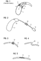
- a housing 1 of a behind-the-ear hearing device has molded-in structures 2 on the inside, which serve to fix a receiver 3. So that the earpiece 3 is not rigidly connected to these structures 2, one or more damping elements 4 are brought between the earpiece 3 and the structure 2 or the hearing aid housing 1. As a result, it can largely be avoided that structure-borne noise reaches the built-in microphone 5 practically unattenuated by the receiver 3 via the hearing device housing 1. In this way, it is thus possible to largely avoid feedback in a hearing device with a built-in receiver 3.
- vibrations of the earpiece 10 can be transmitted to the hearing aid housing 12 via a tube of hearing aid 11.
- the built-in the hearing aid housing 12 microphone 13 absorbs these transmitted vibrations as structure-borne noise, so that it may cause disturbing feedback.
- a damping element 14 is now mounted in and / or on the receiver tube 11. This damping element 14 has the effect that structure-borne noise is additionally attenuated on its transmission path from the receiver 10 to the microphone 13.
- the damping element 14 consists for example of an additional mass, which reduces the vibrations of the receiver tube 11.
- the damping element 14 is integrated as a foamed tube section in the tube 11. This foamed section then hardly transmits any more vibrations from one part of the receiver tube 11 to the other part.
- FIG. 15 A second embodiment of the receiver tube according to the invention is shown in FIG. Accordingly, the listener tube is formed in a central portion like an accordion 15. About this accordion-like section longitudinal waves, but also transversal waves are hardly transmitted.
- a very simple variant of a damping element according to the invention is that a central portion 16 is designed in accordance with Figure 4 S-shaped. Also, this S-shaped portion 16 dampens shear forces in the handset tube eleventh
- a wire mesh 17 is inserted into a part region of the receiver tube 11 in the interior of the receiver tube during production.
- the inventive Handset hose 11 filter and dampen the desired frequencies.
- the damped receiver tube 11 in which the electrical lines run to the handset 10, reduces the acoustic feedback from the handset 10 to the microphone 13.
- the need to attenuate transmitted via the listener tube structure-borne sound Even with such hearing aids it comes namely to signal distortions when the useful sound, which is passed from the handset 3 through the handset tube into the ear, is distorted by Störschallanmaschine which also enter the ear via the Hörerschlauchwand.
- the dampened tube according to the present invention can also be used profitably.
- the desired damping levels can be achieved for one or more frequencies.
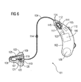
- FIG. 6 shows a behind-the-ear hearing device 101, which comprises a housing part 102 that can be worn behind the ear, an earmold piece 103 that can be worn in the ear, and a receiver tube 104 that connects the housing part 102 to the earmold piece 103.
- a microphone 105 is present. The electrical input signal output by the microphone 105 is supplied to a signal processing and amplifier unit 106 to compensate for the hearing loss of a user.
- the resulting electrical output signal is supplied via electrical lines 123, 124 and 125 to a receiver 107, which converts the electrical output signal into an acoustic output signal and emits via a sound channel 108 into the auditory canal of the user.
- a ventilation channel is used to ventilate the auditory canal volume enclosed by the earmold 103 (Vent) 109.
- the hearing device 101 comprises a user-operable control element 110 and a voltage source in the form of a battery 126 for supplying power to the electronic components of the hearing aid 101.
- the earphone tube 104 is made of a relatively rigid plastic material.
- the handset tube 104 may be e.g. be adapted under heat to the individual anatomical conditions of the user. Following such an adjustment, it is elastically deformable.
- the receiver tube 104 encloses the electrical lines 124 for the electrical connection of the receiver 107 with the signal processing and amplifier unit 106.
- the earphone tube 104 is detachably connected both to the earmold piece 103 and to the housing part 102.
- the releasable electrical and mechanical connection via contact pins 116 and 120, which are inserted into corresponding sockets 118 and 122 in the housing part 102 and the earmold 103.
- the plug member 115 is floatingly mounted in the vibration damping material consisting of damping element 112.
- the socket part 117 with the bushing 118 in a corresponding damping element 111 at the end of the housing part 102 is floatingly mounted.
- the transmission of mechanical vibrations from the receiver tube 104 to the housing part 102 is largely prevented.
- the second end of the receiver tube 104 is correspondingly decoupled from the earmold 103 in terms of vibration technology.
- the plug part 119 at the opposite end of the receiver tube 104 with the plug 120 directly, ie without vibration suppressing measures attached to the handset tube 104.
- the bushing part 121 is floatingly mounted with the sleeve 122 in the damping element 113 of vibration-damping material. As a result, the transmission of mechanical vibrations is suppressed by the earmold on the handset tube 104.
- a damping element 114 is present in the tube 104. This divides the listener tube 104 into two sections which are connected to each other in a vibration-damping manner.
- a user-friendly and easy-to-maintain hearing aid 101 with the three detachably interconnected components earmold 103, earphone tube 104 and housing part 102 is created by the measures shown, in which the transmission of mechanical vibrations of the earmold 103 to the housing part 102 is largely prevented.
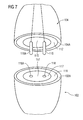
- FIG. 7 shows a detailed view of the plug connection between the receiver tube 104 and the housing part 102.
- the plug part 115 At the end of the receiver tube 104 is the plug part 115 with the two contact pins 116 and 116A.
- the plug part 115 is separated from the plastic material of the receiver tube 104 by means of the damping unit 112 made of vibration-damping material.
- the plug part 115 is floatingly mounted in the damping element 112. There is thus no direct connection between the plug part 115 and the plastic material of the outer shell 104A of the socket part 104.
- the socket part 117 with the two bushes 118 and 118A is separated by the damping element 111 from the housing of the housing part 102 and in particular in the Damping element 111 floating.
Landscapes
- Health & Medical Sciences (AREA)
- General Health & Medical Sciences (AREA)
- Neurosurgery (AREA)
- Otolaryngology (AREA)
- Physics & Mathematics (AREA)
- Engineering & Computer Science (AREA)
- Acoustics & Sound (AREA)
- Signal Processing (AREA)
- Soundproofing, Sound Blocking, And Sound Damping (AREA)
- Headphones And Earphones (AREA)
Applications Claiming Priority (1)
| Application Number | Priority Date | Filing Date | Title |
|---|---|---|---|
| DE102005036849A DE102005036849A1 (de) | 2005-08-04 | 2005-08-04 | Hörerschlauch mit Dämpfungselement und entsprechende Hörvorrichtung |
Publications (1)
| Publication Number | Publication Date |
|---|---|
| EP1750480A1 true EP1750480A1 (fr) | 2007-02-07 |
Family
ID=37156020
Family Applications (1)
| Application Number | Title | Priority Date | Filing Date |
|---|---|---|---|
| EP06016347A Withdrawn EP1750480A1 (fr) | 2005-08-04 | 2006-08-04 | Prothèse auditive avec un elément d'amortissement |
Country Status (3)
| Country | Link |
|---|---|
| US (1) | US7783068B2 (fr) |
| EP (1) | EP1750480A1 (fr) |
| DE (1) | DE102005036849A1 (fr) |
Cited By (5)
| Publication number | Priority date | Publication date | Assignee | Title |
|---|---|---|---|---|
| WO2008015295A2 (fr) | 2006-10-11 | 2008-02-07 | Phonak Ag | Dispositif auditif |
| EP2015605A2 (fr) | 2007-07-09 | 2009-01-14 | Siemens Audiologische Technik GmbH | Appareil auditif |
| EP2456235A1 (fr) * | 2010-11-17 | 2012-05-23 | Yamaichi Electronics Deutschland GmbH | Appareil auditif, connecteur, utilisation d'un connecteur et système de connexion d'un appareil auditif à un câble |
| DE102011006720A1 (de) | 2011-04-04 | 2012-10-04 | Siemens Medical Instruments Pte. Ltd. | Gehörgangseinsatz mit einem Filterelement |
| DE102019202651A1 (de) | 2019-02-27 | 2020-01-23 | Sivantos Pte. Ltd. | Schallschlauch und HdO-Hörgerät |
Families Citing this family (14)
| Publication number | Priority date | Publication date | Assignee | Title |
|---|---|---|---|---|
| US8333260B1 (en) * | 2005-04-25 | 2012-12-18 | Hall John A | Deep insertion vented earpiece system |
| DE102007033289A1 (de) * | 2007-07-17 | 2009-01-22 | Siemens Audiologische Technik Gmbh | Anordnung mit Tragehaken für Hörgeräte und dazugehöriges Verfahren |
| DE102007052648A1 (de) * | 2007-11-05 | 2009-05-07 | Siemens Medical Instruments Pte. Ltd. | Hörhilfsgerät, insbesondere HdO-Hörgerät |
| DE102008007553A1 (de) * | 2008-02-05 | 2009-08-13 | Siemens Medical Instruments Pte. Ltd. | Hörgerät mit akustischem Dämpfer |
| EP2117258A1 (fr) * | 2008-05-07 | 2009-11-11 | Cochlear Limited | Ajustement de longueur de câble dans des dispositifs d'aide auditive |
| US9161131B2 (en) * | 2010-03-25 | 2015-10-13 | K&E Holdings, LLC | Stereo audio headphone apparatus for a user having a hearing loss and related methods |
| US9781514B2 (en) | 2010-03-25 | 2017-10-03 | K&E Holdings, LLC | Stereo audio headphone apparatus |
| US8406448B2 (en) * | 2010-10-19 | 2013-03-26 | Cheng Uei Precision Industry Co., Ltd. | Earphone with rotatable earphone cap |
| EP2512152B1 (fr) | 2011-04-13 | 2013-11-06 | Oticon A/s | Dispositif auditif avec au moins deux microphones |
| US20120288130A1 (en) * | 2011-05-11 | 2012-11-15 | Infineon Technologies Ag | Microphone Arrangement |
| CN104378708A (zh) * | 2014-11-11 | 2015-02-25 | 苏州立人听力器材有限公司 | 带阻尼的助听器双耳听筒 |
| CN107431426B (zh) * | 2015-03-13 | 2019-08-20 | 乌杰尔有限公司 | 用于远程提供来自振动换能器的振动的系统 |
| EP4117309B1 (fr) | 2017-12-28 | 2025-05-07 | Starkey Laboratories, Inc. | Câble pour un appareil auditif à récepteur à l'intérieur du canal |
| GB201907610D0 (en) | 2019-05-29 | 2019-07-10 | Pss Belgium Nv | Loudspeaker |
Citations (8)
| Publication number | Priority date | Publication date | Assignee | Title |
|---|---|---|---|---|
| GB2039191A (en) * | 1978-12-15 | 1980-07-30 | Danavox As | Hookshaped part of a behind-the ear hearing aid |
| DE3141921A1 (de) | 1981-10-22 | 1983-05-05 | Robert Bosch Gmbh, 7000 Stuttgart | "hoergeraet" |
| DE8905756U1 (de) * | 1989-05-08 | 1989-07-13 | Siemens AG, 1000 Berlin und 8000 München | Hinter dem Ohr zu tragendes Hörgerät mit einer Belüftung zum Gehörgang |
| US5606621A (en) * | 1995-06-14 | 1997-02-25 | Siemens Hearing Instruments, Inc. | Hybrid behind-the-ear and completely-in-canal hearing aid |
| DE29801567U1 (de) | 1998-01-30 | 1998-04-16 | Siemens Audiologische Technik | Hinter dem Ohr tragbares Hörhilfegerät |
| US6275596B1 (en) | 1997-01-10 | 2001-08-14 | Gn Resound Corporation | Open ear canal hearing aid system |
| US6766030B1 (en) | 1999-04-19 | 2004-07-20 | Sunil Chojar Llc | Hearing aid receiver with external mechanical shock and vibration damper and hearing aid that uses it |
| EP1484943A2 (fr) | 1999-06-16 | 2004-12-08 | Phonak Ag | Prothese auditive retro-auriculaire |
Family Cites Families (2)
| Publication number | Priority date | Publication date | Assignee | Title |
|---|---|---|---|---|
| US5046580A (en) * | 1990-08-17 | 1991-09-10 | Barton James I | Ear plug assembly for hearing aid |
| US5412736A (en) * | 1992-03-23 | 1995-05-02 | Keliiliki; Shawn P. | Personal audio system and earphone for same |
-
2005
- 2005-08-04 DE DE102005036849A patent/DE102005036849A1/de not_active Withdrawn
-
2006
- 2006-08-04 EP EP06016347A patent/EP1750480A1/fr not_active Withdrawn
- 2006-08-04 US US11/499,487 patent/US7783068B2/en not_active Expired - Fee Related
Patent Citations (8)
| Publication number | Priority date | Publication date | Assignee | Title |
|---|---|---|---|---|
| GB2039191A (en) * | 1978-12-15 | 1980-07-30 | Danavox As | Hookshaped part of a behind-the ear hearing aid |
| DE3141921A1 (de) | 1981-10-22 | 1983-05-05 | Robert Bosch Gmbh, 7000 Stuttgart | "hoergeraet" |
| DE8905756U1 (de) * | 1989-05-08 | 1989-07-13 | Siemens AG, 1000 Berlin und 8000 München | Hinter dem Ohr zu tragendes Hörgerät mit einer Belüftung zum Gehörgang |
| US5606621A (en) * | 1995-06-14 | 1997-02-25 | Siemens Hearing Instruments, Inc. | Hybrid behind-the-ear and completely-in-canal hearing aid |
| US6275596B1 (en) | 1997-01-10 | 2001-08-14 | Gn Resound Corporation | Open ear canal hearing aid system |
| DE29801567U1 (de) | 1998-01-30 | 1998-04-16 | Siemens Audiologische Technik | Hinter dem Ohr tragbares Hörhilfegerät |
| US6766030B1 (en) | 1999-04-19 | 2004-07-20 | Sunil Chojar Llc | Hearing aid receiver with external mechanical shock and vibration damper and hearing aid that uses it |
| EP1484943A2 (fr) | 1999-06-16 | 2004-12-08 | Phonak Ag | Prothese auditive retro-auriculaire |
Cited By (10)
| Publication number | Priority date | Publication date | Assignee | Title |
|---|---|---|---|---|
| WO2008015295A2 (fr) | 2006-10-11 | 2008-02-07 | Phonak Ag | Dispositif auditif |
| WO2008015295A3 (fr) * | 2006-10-11 | 2008-03-20 | Phonak Ag | Dispositif auditif |
| US8311252B2 (en) | 2006-10-11 | 2012-11-13 | Phonak Ag | Hearing device |
| EP2015605A2 (fr) | 2007-07-09 | 2009-01-14 | Siemens Audiologische Technik GmbH | Appareil auditif |
| DE102007031872A1 (de) * | 2007-07-09 | 2009-01-15 | Siemens Audiologische Technik Gmbh | Hörgerät |
| DE102007031872B4 (de) * | 2007-07-09 | 2009-11-19 | Siemens Audiologische Technik Gmbh | Hörgerät |
| EP2456235A1 (fr) * | 2010-11-17 | 2012-05-23 | Yamaichi Electronics Deutschland GmbH | Appareil auditif, connecteur, utilisation d'un connecteur et système de connexion d'un appareil auditif à un câble |
| DE102011006720A1 (de) | 2011-04-04 | 2012-10-04 | Siemens Medical Instruments Pte. Ltd. | Gehörgangseinsatz mit einem Filterelement |
| EP2509340A1 (fr) | 2011-04-04 | 2012-10-10 | Siemens Medical Instruments Pte. Ltd. | Installation de conduit auditif dotée d'un élément de filtrage |
| DE102019202651A1 (de) | 2019-02-27 | 2020-01-23 | Sivantos Pte. Ltd. | Schallschlauch und HdO-Hörgerät |
Also Published As
| Publication number | Publication date |
|---|---|
| US20070036381A1 (en) | 2007-02-15 |
| DE102005036849A1 (de) | 2007-02-22 |
| US7783068B2 (en) | 2010-08-24 |
Similar Documents
| Publication | Publication Date | Title |
|---|---|---|
| EP1750480A1 (fr) | Prothèse auditive avec un elément d'amortissement | |
| DE69912289T2 (de) | Kopfhörer | |
| DE69521942T2 (de) | Supra-Ohr-Kopfhörer zur aktiven Rauschverminderung | |
| DE102012220096B4 (de) | Außengeräusche einleitender Ohrhörer | |
| EP1061772B1 (fr) | Corps tubulaire de transmission sonore, notamment pour prothèses auditives | |
| DE3719963C2 (de) | Schutzvorrichtung gegen Lärmeinwirkungen | |
| WO2010031775A1 (fr) | Écouteur intra-auriculaire et adaptateur d'extension | |
| EP1335630B1 (fr) | Prothèse auditive à porter dans l'oreille ou prothèse auditive avec un élément otoplastique à porter dans l'oreille | |
| EP1874093A2 (fr) | Appareil auditif doté d'une fixation pour un conduit auditif | |
| EP2219392B1 (fr) | Module de microphone pour un dispositif auditif | |
| WO2009071570A2 (fr) | Écouteur | |
| EP1993324A2 (fr) | Pièce d'ajustage auditif dotée d'un joint d'adaptateur | |
| EP3614699B1 (fr) | Instrument auditif doté d'une unité d'accouplement destiné à supporter un écouteur par amortissement de vibrations | |
| EP2302953B1 (fr) | Appareil auditif à conduction osseuse | |
| EP2007172A1 (fr) | Petit tuyau de sortie acoustique doté d'une structure à 2 composants | |
| DE4010372C2 (fr) | ||
| DE102005044495A1 (de) | In-Ear-Headset und In-Ear-Hörer | |
| WO2014161885A1 (fr) | Écouteur intra-auriculaire et ensemble embout auriculaire pour écouteur | |
| WO2018234132A1 (fr) | Écouteur intra-auriculaire | |
| DE102018214322A1 (de) | Dämpfungseinrichtung für einen Hörer eines Hörinstruments sowie Hörinstrument mit einer solchen Dämpfungseinrichtung | |
| DE102010019633A1 (de) | Hörermodul | |
| DE202015100370U1 (de) | Ohrhörermodul und Wiedergabevorrichtung | |
| DE959376C (de) | Kohlemikrophon mit Schalltrichter | |
| DE102016104598A1 (de) | Demonstrationsvorrichtung für Hörgeräte | |
| EP1585366A2 (fr) | Composants d'une prothèse auditive insonorisée et procédé de insonorisation correspondante |
Legal Events
| Date | Code | Title | Description |
|---|---|---|---|
| PUAI | Public reference made under article 153(3) epc to a published international application that has entered the european phase |
Free format text: ORIGINAL CODE: 0009012 |
|
| AK | Designated contracting states |
Kind code of ref document: A1 Designated state(s): AT BE BG CH CY CZ DE DK EE ES FI FR GB GR HU IE IS IT LI LT LU LV MC NL PL PT RO SE SI SK TR |
|
| AX | Request for extension of the european patent |
Extension state: AL BA HR MK YU |
|
| 17P | Request for examination filed |
Effective date: 20070806 |
|
| AKX | Designation fees paid |
Designated state(s): AT BE BG CH CY CZ DE DK EE ES FI FR GB GR HU IE IS IT LI LT LU LV MC NL PL PT RO SE SI SK TR |
|
| STAA | Information on the status of an ep patent application or granted ep patent |
Free format text: STATUS: THE APPLICATION IS DEEMED TO BE WITHDRAWN |
|
| 18D | Application deemed to be withdrawn |
Effective date: 20140301 |