EP1750820B2 - Computersimulationssteuersystem - Google Patents
Computersimulationssteuersystem Download PDFInfo
- Publication number
- EP1750820B2 EP1750820B2 EP04730378.9A EP04730378A EP1750820B2 EP 1750820 B2 EP1750820 B2 EP 1750820B2 EP 04730378 A EP04730378 A EP 04730378A EP 1750820 B2 EP1750820 B2 EP 1750820B2
- Authority
- EP
- European Patent Office
- Prior art keywords
- seat
- back support
- control system
- frame
- control module
- Prior art date
- Legal status (The legal status is an assumption and is not a legal conclusion. Google has not performed a legal analysis and makes no representation as to the accuracy of the status listed.)
- Expired - Lifetime
Links
- 238000005094 computer simulation Methods 0.000 title claims abstract description 18
- 230000007246 mechanism Effects 0.000 claims abstract description 17
- 230000008878 coupling Effects 0.000 claims abstract description 9
- 238000010168 coupling process Methods 0.000 claims abstract description 9
- 238000005859 coupling reaction Methods 0.000 claims abstract description 9
- 238000000034 method Methods 0.000 claims description 4
- 239000002184 metal Substances 0.000 claims description 2
- 238000004088 simulation Methods 0.000 description 4
- 239000000463 material Substances 0.000 description 3
- 230000001133 acceleration Effects 0.000 description 1
- 238000004590 computer program Methods 0.000 description 1
- 239000013013 elastic material Substances 0.000 description 1
- -1 push buttons Substances 0.000 description 1
- 230000001052 transient effect Effects 0.000 description 1
Images




Classifications
-
- A—HUMAN NECESSITIES
- A47—FURNITURE; DOMESTIC ARTICLES OR APPLIANCES; COFFEE MILLS; SPICE MILLS; SUCTION CLEANERS IN GENERAL
- A47C—CHAIRS; SOFAS; BEDS
- A47C7/00—Parts, details, or accessories of chairs or stools
- A47C7/36—Supports for the head or the back
- A47C7/40—Supports for the head or the back for the back
- A47C7/407—Supports for the head or the back for the back of collapsible type
-
- A—HUMAN NECESSITIES
- A63—SPORTS; GAMES; AMUSEMENTS
- A63F—CARD, BOARD, OR ROULETTE GAMES; INDOOR GAMES USING SMALL MOVING PLAYING BODIES; VIDEO GAMES; GAMES NOT OTHERWISE PROVIDED FOR
- A63F13/00—Video games, i.e. games using an electronically generated display having two or more dimensions
- A63F13/90—Constructional details or arrangements of video game devices not provided for in groups A63F13/20 or A63F13/25, e.g. housing, wiring, connections or cabinets
-
- A—HUMAN NECESSITIES
- A63—SPORTS; GAMES; AMUSEMENTS
- A63F—CARD, BOARD, OR ROULETTE GAMES; INDOOR GAMES USING SMALL MOVING PLAYING BODIES; VIDEO GAMES; GAMES NOT OTHERWISE PROVIDED FOR
- A63F13/00—Video games, i.e. games using an electronically generated display having two or more dimensions
- A63F13/80—Special adaptations for executing a specific game genre or game mode
- A63F13/803—Driving vehicles or craft, e.g. cars, airplanes, ships, robots or tanks
-
- A—HUMAN NECESSITIES
- A63—SPORTS; GAMES; AMUSEMENTS
- A63F—CARD, BOARD, OR ROULETTE GAMES; INDOOR GAMES USING SMALL MOVING PLAYING BODIES; VIDEO GAMES; GAMES NOT OTHERWISE PROVIDED FOR
- A63F13/00—Video games, i.e. games using an electronically generated display having two or more dimensions
- A63F13/90—Constructional details or arrangements of video game devices not provided for in groups A63F13/20 or A63F13/25, e.g. housing, wiring, connections or cabinets
- A63F13/98—Accessories, i.e. detachable arrangements optional for the use of the video game device, e.g. grip supports of game controllers
-
- A—HUMAN NECESSITIES
- A63—SPORTS; GAMES; AMUSEMENTS
- A63G—MERRY-GO-ROUNDS; SWINGS; ROCKING-HORSES; CHUTES; SWITCHBACKS; SIMILAR DEVICES FOR PUBLIC AMUSEMENT
- A63G31/00—Amusement arrangements
- A63G31/16—Amusement arrangements creating illusions of travel
Definitions
- the present invention relates to a computer simulation control system, comprising:
- Such a computer simulation control system is known from the racing car industry. After assembly, said at least one control module and the seat are coupled to each other by said coupling mechanism.
- the control module comprises, for example, a steering wheel which is positioned in front of the seat -in a suitable driving position- for a race simulation.
- the computer may be, for instance, an external home computer, personal computer, game computer and the like.
- Control modules for controlling computer simulator programs are known and marketed by, for instance, Logitech tm .
- a user takes place in the seat for handling said at least one control module.
- the control module is usually connected to a computer which runs said simulator program, for controlling that program.
- the assembled control system provides a high reality simulation environment and particularly a relatively real feel of the simulation environment during the control of the simulator program.
- a disadvantage of the known computer simulation control system is, that it requires relatively much space. Therefore, the transportation and/or storage of the known system is relatively complex and expensive. Particularly, only a relatively small number of control systems can be packed in one loading volume, for instance in one shipping container or in one trailer compartment, leading to high transportation costs per control system. Besides, the handling of a relatively large control system during transport thereof is relatively difficult, and may lead to collisions which might damage sensitive parts of the system. Furthermore, it may be desired to move the control system from one place to another by an end-user, so that the system can be used in different locations. This is also relatively difficult to accomplish in view of said handling problems of the system.
- DE 100 09 615 discloses a vehicle drive simulator movement system e.g. for automobile, including a drive system for simulating lateral transient acceleration forces by computer via control unit.
- JP11-179051 discloses a body feeling chair with a video game operation function for a household, including a seat board and a back board shared to the average figure of a human.
- the back board and seat board are pivotally connected.
- the present invention aims to improve the computer simulation control system.
- the invention aims to provide a computer simulation control system, wherein the system can be transported, stored and/or handled relatively safe and easy.
- the computer simulation system of the present invention is characterized by the features of claim 1.
- the back support of the seat is movable between a first position, in which first position the back support extends at an operating angle upwardly from said seat part for supporting at least part of the back of a user, and a second position, in which second position the back support does not extend at said operating angle upwardly from the seat part, wherein said-back support extends substantially opposite the seat part when the back support is in the second position, wherein said seat part comprises a seat frame, wherein said back support comprises a back support frame, wherein the seat frame and back support frame comprise frame connectors for movably connecting these frames to each other, wherein the seat frame comprises a bottom frame part and a rear frame part, the rear frame part extending at said operating angle upwardly from the bottom frame part, wherein the back support frame is movably connected to said rear frame part of the seat frame.
- said back support is in the first position, for creating a relatively real simulator control environment.
- the back support can simply be moved to the second position, for instance a substantially horizontal position, particularly for reducing the overall dimensions of the control system, and more particularly for reducing the height of the system.
- the control system can be transported, stored and/or handled relatively easy, for example in a relatively small area. This further leads to a substantial reduction of transporting and/or storing costs.
- the seat of the computer simulation control system can simply be arranged as described above, leading to said advantages.
- the back support and the seat part of the seat are detachably connected, for instance with a hinge system, to each other when the back support is in the first position, for moving the back support to the second position.
- the back support can simply be removed from the seat part, to further reducing the overall dimensions of the system.
- the back support and the seat part of the seat are pivotally connected to each other, such that the back support is pivotal, about a pivot axis, between said first and second position. Therefore, the back support can be folded up towards the seat part of the seat.This results in the overall system dimensions being reduced substantially.
- the seat of the control system has a maximum first height when the back support of the seat is in the first position, wherein the control system has a second maximum height when the back support is in the second position, wherein said second maximum height is less than half said first maximum height.
- the height of the system can be reduced by half or even more, preferably also leading to a reduction of transport volume by a factor 2 or more. Therefore, transportation and/or handling costs of each computer simulation control system may also be reduced by about the same amount, of a factor 2 or more.
- the back support and the seat part are arranged to at least partially enclose a storage space when the back support is in the second position.
- Such a storage space can be used for safely storing various objects and the like, wherein the back support and seat part of the seat can serve to protect such objects from being damaged.
- the storage space is arranged for receiving said control module or at least part thereof, particularly during transportation and/or storage of the control system.
- the overall computer simulation control system can be stored and/or transported in a very compact manner, wherein -furthermore-said at least part of said control module is being protected well within said storage space.
- Such protection is further improved when the seat part and back support are provided with one or more relatively soft upholstering materials.
- the present invention also provides a use of a control system according to any of the claims 1-19, wherein said back support is moved from said first position to said second position and/or vice-versa. For instance, said back support is moved to said second position when the control system is to be stored and/or transported safely and with ease. The back support is simply moved to the first position when the control system is to be used for controlling a computer simulator program. Then, the assembled system can provide a relatively real feeling of, for example, the driving seat of a simulated racing car, for the case that the system is used in combination with a racing simulator program.
- the present invention further provides a method for handling a computer simulation control system according to any of claims 1-19, wherein said back support is being moved to said second position for transportation and/or storage of the control system.
- at least part of said control module for example at least a steering wheel and/or at least one foot pedal, is being arranged between said seat part and said back support.
- a relatively compact system can be obtained, wherein said at least part of the control module can be protected by the seat part and the back support.
- said back support is being moved from said second position to said first position for supporting at least part of the back of a user.
- the present invention also provides a container, for example a box, which is characterized by the features of claim 25.
- the container advantageously comprises a computer simulation control system according to any of claims 1-19, wherein the back support of the seat is positioned in said second position, wherein the back support extends substantially opposite the seat part of the seat. Therefore, the container can be relatively compact, requiring little storage and/or transportation space. Also, such container can be handled relatively easy, preferably by a single person, and for example stored in a relatively compact trunk of a private car. Besides, it is advantageous when at least part of said control module is located in a storage space, which storage space is at least partially enclosed by said seat part and said back support of the seat. Therefore, the seat of the control system serves as an inner container for storing said control module or control module part.
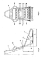
- said control module for controlling a computer simulator program comprises a steering column with a steering wheel 1 and two foot pedals 2.
- Said mechanism for coupling the seat and the control module 1, 2 comprises an elongated element 5, for example a rigid bar, extending from a lower part 15 of the seat towards the at least one control module 1, 2.
- Said lower seat part 15 comprises seat support members 15 which extend below said seat part 3.
- Said seat part 3 also comprises substantially upwardly extending side parts 16, particularly for forming a bucket seat.
- the back support 4 comprises shoulder supports 25.
- control module 1, 2 is connected to computing means or the like for controlling one or more computer programs being run thereon.
- control system is arranged for controlling a computer racing simulation.
- one or more displays are provided for displaying a virtual simulator environment. Said computing means and display are not shown in the present figures.
- said seat part of the present embodiment comprises a seat frame 6, and said back support comprises a back support frame 8.
- the frames 6, 8 may be assembled, for instance, from suitable metal tubes or the like.
- Each of said frames 6, 8 is provided with support springs 17.
- the back support frame comprises shoulder support frame parts 25a.
- the seat is also provided with a suitable upholstering comprising a cover 13, extending over the seat part 3 as well as over the back support 4.
- the seat also comprises a suitable filling, padding, and the like, extending between the covering 13, said frames 6, 8 and said support springs 17 for providing comfort.
- Said cover 3 is preferably arranged, to cover substantially all outer surfaces of the seat, including or excluding the downwardly facing side of the seat part.
- the cover 13 can provide a good protection of the seat parts enclosed thereby, as well as provide a esthetically pleasant and finished look.
- the seat frame 6 comprises a substantially horizontal extending bottom frame part 6a, viewed when the control system is the assembled operating position.
- the seat frame 6 comprises a rear frame part 6b extending substantially at a certain operating angle ⁇ upwardly with respect to the bottom frame part 6a.
- Said angle may comprise various angles, for example an angle ⁇ in the range of about 90-135° or an other suitable angle.
- the back support frame 8 extends substantially in line with the rear frame part 6b of the seat frame 6, so that the back support 4 extends substantially at the same operating angle ⁇ upwardly with respect to said seat part 3. In that first position, the back support is available for supporting at least part of the back of a user.
- the seat frame 6 comprises side support frame parts 16a for providing rigid bucket seat side parts 16.
- the seat frame 6 and back support frame 8 comprise frame connectors 7 for movably connecting these frames 6, 8 to each other.
- the back support 4 of the seat is at least movable between said first position and a second position.
- This second position of the back support 4 is shown in figures 7-8 .
- the back support 4 does not extend at said operating angle ⁇ upwardly from the seat part 3, but substantially opposite the seat part 3.
- the back support 4 is laying substantially horizontally in said second position.
- the control system is relatively compact, which is advantageous for transportation and/or storage thereof.
- the back support 4 and the seat part 3 of the seat are pivotally connected to each other, such that the back support 4 is pivotal about a pivot axis 10 between said first and second position.
- the frame connectors comprise suitable hinges 7 which connect the back support frame 8 to the rear frame part 6b of the seat part.
- the back support 4 and the seat part 3 of the seat may be, for example, detachably connected to each other when the back support 4 is in the first position, for moving the back support 4 to a suitable second position.
- a detachable connection can be provided in various ways.
- opposite ends of the frames 6, 8 of the back support 4 and the seat part 3 of the seat may be arranged to be clamped, slid and/or clicked detachably onto each other.
- the rear frame of the seat part may comprise upwardly extending tubes or bushes which receive downwardly extending pins of the back support frame 4 for providing such detachable connection.
- each locking mechanism comprises a bush 11 and a bolt 12. Said bush 11 and the respective bolt 12 are arranged to cooperate with each other for locking the back support 4 in its first position.
- each bush 11 is attached to said seat frame 6.Each bolt 12 is movably connected to said back support frame 8 by a guiding bush 31 which is connected to that frame 8.
- each bolt 12 comprises an extending gripping member 12a for alleviating the manual handling thereof, and for retaining the bolt in said upper, withdrawn, position in cooperation with a retainer 30.
- the locking mechanism may be arranged in various ways, comprising for example one or more controllable locking parts, pins, spring means and the like.
- the back support 4 and the seat part 3 are advantageously arranged to at least partially enclose a storage space S when the back support 4 is in the second position.
- the storage space S is preferably arranged and suitable for receiving said control module 1, 2 or at least part thereof when the control system has been disassembled, particularly during transportation and/or storage of the control system. In that case, a very compact configuration can be achieved, particularly for transport and/or storage.
- the cover part 13a extending over the rear side of the seat is at least partially detachably connected to said seat part 3.
- the cover 13 may comprise one or more sections, extending at the rear side of the seat, which are detachably connected to the seat part.
- Such detachable connection can be provided by various means, for example Velcro tm material, push buttons, elastic material, wire material, strings and/or other suitable means.
- the seat of the control system has a maximum first height H1 when the back support 4 of the seat is in the first position.
- the second position of the back support 4 is such, that the seat of the control system has a second maximum height H2 when the back support 4 is in that second position.
- the second maximum height H2 is less than half said first maximum height H1, as follows from figures 4 and 8 .
- the length L2 of the back support 4 of the seat is about the same as the length L1 of the seat part 3 of the seat.
- the length L2 of the back support 4 of the seat is may be only about 0 to 10 % larger or smaller than length L1 of the seat 3.
- Other length ratios -although less preferably- may also be used.
- the first auxiliary request control system can be made relatively compact by bringing the back support to its second position, as shown in figures 6-8 .
- the seat serves as a inner container for containing and protecting sensitive parts of the control system, for instance said control module 1, 2.
- a computer for running simulator software may be stored in said storage space S, provided that the computer has suitable dimensions with respect to the volume of that space S.
- a relatively small box B may then be used for storing the closely packed control system, providing advantages in view of transport and storage safety, simplicity and cost.
- the inner dimensions of such box B are preferably about the same as, or only slightly larger, for instance about 10% or 20%, larger than the maximum outer dimensions of the seat with the back support 4 in the second position, measured in Cartesian x-, y- and z-directions. Other ratios of said dimensions -although less preferably- may also be used.
- Such box B may also be arranged to contain other objects in combination with the folded-in seat, for example said coupling mechanism 3, said seat support members 15 and the like.
- the computer simulation control system can be suitable for use in combination with a driving simulator program, a racing simulator program, a flying simulator program or the like.
- the system may comprise one or more control modules, wherein each module may be provided with one or more controls, for instance a wheel, pedal, force-feedback controls and/or the like.
- Said mechanism for coupling the seat and the at least one control module to each other may be arranged in various ways.
- such mechanism may be attached to or be detachably connected to the seat.
- such mechanism may be attached to or be detachably connected to said control module.
- the mechanism may be adjustable to adjust the position of the seat and said control module with respect to each other, particularly for providing a comfortable control environment to a user.
Landscapes
- Engineering & Computer Science (AREA)
- Multimedia (AREA)
- Seats For Vehicles (AREA)
- Management, Administration, Business Operations System, And Electronic Commerce (AREA)
- Chairs For Special Purposes, Such As Reclining Chairs (AREA)
- Testing And Monitoring For Control Systems (AREA)
- Feedback Control In General (AREA)
- Debugging And Monitoring (AREA)
Claims (27)
- Computersimulationssteuersystem umfassend- wenigstens ein Steuermodul (1, 2) zur Steuerung eines Computersimulationsprogramms,- einen Sitz, der einen Sitzabschnitt (3) und eine Rückenlehne (4) umfasst,- wenigstens einen Mechanismus (5) zum Verbinden des Sitzes mit dem wenigstens einen Steuermodul (1, 2) derart, dass ein Benutzer auf den Sitzabschnitt (3) des Sitzes, zur Handhabung des wenigstens einen Steuermoduls (1, 2) von diesem, gesetzt werden kann,wobei die Rückenlehne (4) des Sitzes zwischen einer ersten Position, in der sie sich mit einem Arbeitswinkel (α) von dem Sitzabschnitt (3) nach oben erstreckt, um wenigstens einen Teil des Rückens eines Benutzers abzustützen, und einer zweiten Position, in der sie sich nicht unter dem Arbeitswinkel (α) von dem Sitzabschnitt (3) nach oben erstreckt, beweglich ist, wobei die Rückenlehne (4) sich im Wesentlichen zum Sitzabschnitt (3) gegenüberliegend erstreckt, wenn die Rückenlehne (4) sich in der zweiten Position befindet, wobei der Sitzabschnitt einen Sitzrahmen (6), die Rückenlehne, einen Rückenabstützrahmen (8) umfasst, wobei der Sitzrahmen (6) und der Rückenabstützrahmen (8) Rahmenverbinder (7) zum beweglichen Verbinden dieser Rahmen (6, 8) miteinander umfassen, wobei der Sitzrahmen (6) einen unteren Rahmenabschnitt (6a) und einen rückwärtigen Rahmenabschnitt (6b) umfasst, wobei der rückwärtige Rahmenabschnitt (6b) sich unter dem Arbeitswinkel (α) von dem unteren Rahmenabschnitt (6a) aufwärts erstreckt, wobei der Rückenabstützrahmen (8) mit dem rückwärtigen Rahmenabschnitt (6b) des Sitzrahmens (6) beweglich verbunden ist.
- Steuersystem gemäß Anspruch 1, wobei die zweite Position eine im Wesentlichen horizontale Position ist.
- Steuersystem gemäß Anspruch 1 oder 2, wobei die Rückenlehne (4) und der Sitzabschnitt (3) derart ausgebildet sind, dass sie wenigstens teilweise einen Aufbewahrungsraum (S) umschließen, wenn die Rückenlehne (4) sich in der zweiten Position befindet.
- Steuersystem gemäß Anspruch 3, wobei der Aufbewahrungsraum (S) zur Aufnahme wenigstens eines Teils des Steuermoduls (1, 2), insbesondere während des Transports und/oder der Lagerung des Steuersystems, ausgebildet ist.
- Steuersystem gemäß einem der vorangehenden Ansprüche, wobei der Sitzabschnitt (3) sich im Wesentlichen aufwärts erstreckende Seitenabschnitte, insbesondere zur Bildung eines Schalensitzes, umfasst.
- Steuersystem gemäß einem der vorangehenden Ansprüche, wobei der Sitzrahmen (6) und der Rückenabstützrahmen (8) aus Metallrohren zusammengebaut sind.
- Steuersystem gemäß einem der vorangehenden Ansprüche, wobei der Sitzrahmen (6) einen sich im Wesentlichen horizontal erstreckenden unteren Rahmenabschnitt (6a) umfasst.
- Steuersystem gemäß einem der vorangehenden Ansprüche, wobei die Rückenlehne (4) und der Sitzabschnitt (3) des Sitzes derart schwenkbar miteinander verbunden sind, dass die Rückenlehne (4) um eine Schwenkachse (10) zwischen einer ersten und einer zweiten Position verschwenkbar ist.
- Steuersystem gemäß einem der vorangehenden Ansprüche, das sich unter dem Sitzabschnitt (3) erstreckende Sitzabstützelemente (15) umfasst.
- Steuersystem gemäß einem der vorangehenden Ansprüche umfassend wenigstens einen Verriegelungsmechanismus (11, 12) zum Verriegeln der Rückenlehne (4) des Sitzes mit dem Sitzabschnitt (3), wenn sich die Rückenlehne (4) in der ersten Position befindet.
- Steuersystem gemäß Anspruch 10, wobei der Verriegelungsmechanismus wenigstens eine Hülse (11) und wenigstens einen Bolzen (12) umfasst, wobei die wenigstens eine Hülse (11) und der wenigstens eine Bolzen (12) zum Verriegeln der Rückenlehne (4) in ihrer ersten Position zusammenwirken.
- Steuersystem gemäß Anspruch 11, wobei jede Hülse (11) an dem Sitzrahmen (6) befestigt ist, wobei jeder Bolzen (12) mit dem Rückenabstützrahmen (8) beweglich verbunden ist.
- Steuersystem gemäß einem der vorangehenden Ansprüche, wobei wenigstens die Rückenlehne (4) einen Bezug (13) umfasst, wobei der Bezug (13) der Rückenlehne mit dem Sitzabschnitt (3) mindestens teilweise lösbar verbunden ist, wobei der Bezug (3) sich nach der Montage des Systems vorzugsweise auch über den Sitzabschnitt (3) erstreckt.
- Steuersystem gemäß einem der vorangehenden Ansprüche, wobei das Steuermodul zur Steuerung eines Computersimulationsprogramms ein Lenkrad (1) umfasst.
- Steuersystem gemäß einem der vorangehenden Ansprüche, wobei das Steuermodul zur Steuerung eines Computersimulationsprogramms wenigstens ein Fußpedal (2) umfasst.
- Steuersystem gemäß einem der vorangehenden Ansprüche, wobei der wenigstens eine Mechanismus zum Verbinden des Sitzabschnitts (3) mit dem wenigstens einen Steuermodul (1, 2) mindestens ein längliches Element (3), beispielsweise eine starre Stange, die sich von dem Sitz zu dem wenigstens einen Steuermodul (1, 2) erstreckt, umfasst.
- Steuersystem gemäß einem der vorangehenden Ansprüche, wobei der Sitz des Steuersystems eine maximale erste Höhe (H1) aufweist, wenn die Rückenlehne (4) des Sitzes sich in der ersten Position befindet, wobei das Steuersystem eine maximale zweite Höhe (H2) aufweist, wenn die Rückenlehne (4) sich in der zweiten Position befindet, wobei die maximale zweite Höhe (H2) weniger als die Hälfte der maximalen ersten Höhe (H1) beträgt.
- Steuersystem gemäß einem der vorangehenden Ansprüche, wobei - bei Betrachtung des Sitzes in der Seitenansicht - die Länge (L2) der Rückenlehne (4) des Sitzes ungefähr genau so groß ist wie die Länge (L1) des Sitzabschnitts (3) des Sitzes.
- Steuersystem gemäß einem der vorangehenden Ansprüche, wobei der Sitz des Steuersystems als ein inwendiges Behältnis zur Aufnahme und zum Schutz von sensiblen Teilen des Steuersystems dient.
- Verwendung eines Steuersystems gemäß einem der Ansprüche 1 bis 19, wobei die Rückenlehne (4) aus der ersten Position in die zweite Position und/oder umgekehrt bewegt wird.
- Verwendung eines Steuersystems gemäß einem der Ansprüche 1 bis 19 zur Steuerung eines Computersimulationsprogramms.
- Verfahren zur Handhabung eines Computersimulationssteuersystems gemäß einem der Ansprüche 1 bis 19, wobei die Rückenlehne zum Transport und/oder zur Lagerung des Steuersystems in die zweite Position bewegt wird.
- Verfahren gemäß Anspruch 22, wobei wenigstens ein Teil des Steuermoduls, beispielsweise wenigstens ein Lenkrad und/oder wenigstens ein Fußpedal, zwischen dem Sitzabschnitt (3) und der Rückenlehne (4) angeordnet wird.
- Verfahren gemäß Anspruch 22 oder 23, wobei die Rückenlehne (4) zum Abstützen wenigstens eines Teils des Rückens des Benutzers von der zweiten Position in die erste Position bewegt wird.
- Behältnis, beispielsweise ein Gehäuse, in Verbindung mit einem Computersimulationssteuersystems gemäß einem der Ansprüche 1 bis 19, wobei die Rückenlehne des Sitzes in der zweiten Position angeordnet ist, wobei sich die Rückenlehne im Wesentlichen gegenüberliegend zum Sitzabschnitt (3) des Sitzes erstreckt.
- Behältnis gemäß Anspruch 25, wobei wenigstens ein Teil des Steuermoduls (1, 2) in einem Aufbewahrungsraum (S) angeordnet ist, der wenigstens teilweise durch den Sitzabschnitt und die Rückenlehne (4) des Sitzes umschlossen ist.
- Behältnis gemäß Anspruch 25 oder 26, wobei die Innenabmessungen des Behältnisses (B) ungefähr gleich groß oder nur geringfügig größer, beispielsweise um 10% oder 20% größer sind, als die maximalen Außenabmessungen des Sitzes, gemessen in kartesischen x-, y- und z-Koordinatenrichtungen, wenn sich die Rückenlehne (4) in der zweiten Position befindet.
Priority Applications (1)
| Application Number | Priority Date | Filing Date | Title |
|---|---|---|---|
| DE602004011692.0T DE602004011692T3 (de) | 2004-04-29 | 2004-04-29 | Computersimulationssteuersystem |
Applications Claiming Priority (1)
| Application Number | Priority Date | Filing Date | Title |
|---|---|---|---|
| PCT/NL2004/000288 WO2005105246A1 (en) | 2004-04-29 | 2004-04-29 | Computer simulation control system |
Publications (3)
| Publication Number | Publication Date |
|---|---|
| EP1750820A1 EP1750820A1 (de) | 2007-02-14 |
| EP1750820B1 EP1750820B1 (de) | 2008-02-06 |
| EP1750820B2 true EP1750820B2 (de) | 2014-12-31 |
Family
ID=34957585
Family Applications (1)
| Application Number | Title | Priority Date | Filing Date |
|---|---|---|---|
| EP04730378.9A Expired - Lifetime EP1750820B2 (de) | 2004-04-29 | 2004-04-29 | Computersimulationssteuersystem |
Country Status (11)
| Country | Link |
|---|---|
| US (1) | US20070099707A1 (de) |
| EP (1) | EP1750820B2 (de) |
| JP (1) | JP2007534998A (de) |
| CN (1) | CN1976744A (de) |
| AT (1) | ATE385433T1 (de) |
| AU (1) | AU2004319054A1 (de) |
| BR (1) | BRPI0418788A (de) |
| CA (1) | CA2565048A1 (de) |
| DE (1) | DE602004011692T3 (de) |
| MX (1) | MXPA06012476A (de) |
| WO (1) | WO2005105246A1 (de) |
Cited By (1)
| Publication number | Priority date | Publication date | Assignee | Title |
|---|---|---|---|---|
| IT201600124141A1 (it) * | 2016-12-07 | 2018-06-07 | Stefano Zanrosso | Sistema di controllo di simulazione computerizzata |
Families Citing this family (10)
| Publication number | Priority date | Publication date | Assignee | Title |
|---|---|---|---|---|
| US7297060B2 (en) | 2004-05-12 | 2007-11-20 | Mattel, Inc. | Transportable apparatus for a game system |
| US7976385B2 (en) | 2004-05-11 | 2011-07-12 | Mattel, Inc. | Game controller with sensitivity adjustment |
| US10360754B2 (en) | 2005-10-19 | 2019-07-23 | Aristocrat Technologies, Inc. | Integrated active control system for managing gaming devices |
| US8560284B2 (en) | 2008-12-04 | 2013-10-15 | Electronics And Telecommunications Research Institute | System and method for alternative simulation of logistics infrastructure |
| DE202009006995U1 (de) * | 2009-05-14 | 2009-08-06 | Schuster, Rainer | Stuhl, Ausleger zur Befestigung an einem Stuhl |
| US9770663B2 (en) | 2014-03-24 | 2017-09-26 | James Curtis Wilkins | Computerized car racing game system |
| CN105894889B (zh) * | 2016-05-09 | 2018-06-12 | 合肥工业大学 | 一种多维可调汽车转向操纵模拟与测试系统的视景控制方法 |
| NL2018898B1 (nl) | 2016-12-23 | 2018-07-02 | Van Beek Maas | Inrichting voor het daarop plaatsen van een stuurwielconsole en pedaalconsole van een racesimulatorspel, alsmede een racesimulator. |
| NL2022326B1 (nl) * | 2018-12-28 | 2020-08-13 | F Smit Holding B V | Stoel, in het bijzonder voor videospellen, en daarbij toe te passen scharnier |
| CN116312132B (zh) * | 2023-03-22 | 2025-09-16 | 苏州鸿翔航空科技有限公司 | 驾驶杆机构 |
Citations (4)
| Publication number | Priority date | Publication date | Assignee | Title |
|---|---|---|---|---|
| GB2329829A (en) † | 1997-10-01 | 1999-04-07 | G & C Home & Leisure Supplies | Play station with adjustable seat, desk and footrest. |
| JPH11179051A (ja) † | 1997-12-18 | 1999-07-06 | Takeshi Yasuda | 家庭用テレビゲーム操作機能付体感椅子 |
| FR2787308A1 (fr) † | 1998-12-22 | 2000-06-23 | Georges Martin | Dispositif de support pour jeux de simulation de conduite ou de pilotage |
| US20020032553A1 (en) † | 2000-04-14 | 2002-03-14 | Barry Simpson | Race car simulator |
Family Cites Families (11)
| Publication number | Priority date | Publication date | Assignee | Title |
|---|---|---|---|---|
| US4879849A (en) * | 1987-11-04 | 1989-11-14 | Omni Films International, Inc. | Point-of-view motion simulator system |
| WO1992016922A1 (en) * | 1991-03-21 | 1992-10-01 | Atari Games Corporation | Vehicle simulator including cross-network feedback |
| DE4434660A1 (de) * | 1994-09-28 | 1996-04-04 | Foerst Reiner | Fahrsimulator mit Antriebsvorrichtung für Roll- und Nickbewegungen |
| US20020055422A1 (en) * | 1995-05-18 | 2002-05-09 | Matthew Airmet | Stationary exercise apparatus adaptable for use with video games and including springed tilting features |
| IL125902A (en) * | 1998-08-24 | 2003-07-31 | Abraham Levin | Vehicle safety system |
| US6089663A (en) * | 1999-02-05 | 2000-07-18 | Spang & Company | Video game accessory chair apparatus |
| DE10009615A1 (de) * | 2000-02-29 | 2001-08-30 | Reiner Foerst | Bewegungssystem für Fahrsimulatoren |
| DE10131399C1 (de) * | 2001-06-28 | 2003-01-16 | Faurecia Autositze Gmbh & Co | Fondsitz für Kraftfahrzeuge |
| US7195486B2 (en) * | 2002-08-06 | 2007-03-27 | Mcgraw Robert W | Reconfigurable simulation structure |
| US7322653B2 (en) * | 2003-06-13 | 2008-01-29 | Vlad Dragusin | Integrated videogaming and computer workstation |
| US7297060B2 (en) * | 2004-05-12 | 2007-11-20 | Mattel, Inc. | Transportable apparatus for a game system |
-
2004
- 2004-04-29 US US10/543,983 patent/US20070099707A1/en not_active Abandoned
- 2004-04-29 WO PCT/NL2004/000288 patent/WO2005105246A1/en not_active Ceased
- 2004-04-29 AU AU2004319054A patent/AU2004319054A1/en not_active Abandoned
- 2004-04-29 DE DE602004011692.0T patent/DE602004011692T3/de not_active Expired - Lifetime
- 2004-04-29 EP EP04730378.9A patent/EP1750820B2/de not_active Expired - Lifetime
- 2004-04-29 BR BRPI0418788-1A patent/BRPI0418788A/pt not_active Application Discontinuation
- 2004-04-29 MX MXPA06012476A patent/MXPA06012476A/es not_active Application Discontinuation
- 2004-04-29 CN CNA2004800434927A patent/CN1976744A/zh active Pending
- 2004-04-29 JP JP2007510634A patent/JP2007534998A/ja not_active Withdrawn
- 2004-04-29 AT AT04730378T patent/ATE385433T1/de not_active IP Right Cessation
- 2004-04-29 CA CA002565048A patent/CA2565048A1/en not_active Abandoned
Patent Citations (4)
| Publication number | Priority date | Publication date | Assignee | Title |
|---|---|---|---|---|
| GB2329829A (en) † | 1997-10-01 | 1999-04-07 | G & C Home & Leisure Supplies | Play station with adjustable seat, desk and footrest. |
| JPH11179051A (ja) † | 1997-12-18 | 1999-07-06 | Takeshi Yasuda | 家庭用テレビゲーム操作機能付体感椅子 |
| FR2787308A1 (fr) † | 1998-12-22 | 2000-06-23 | Georges Martin | Dispositif de support pour jeux de simulation de conduite ou de pilotage |
| US20020032553A1 (en) † | 2000-04-14 | 2002-03-14 | Barry Simpson | Race car simulator |
Cited By (1)
| Publication number | Priority date | Publication date | Assignee | Title |
|---|---|---|---|---|
| IT201600124141A1 (it) * | 2016-12-07 | 2018-06-07 | Stefano Zanrosso | Sistema di controllo di simulazione computerizzata |
Also Published As
| Publication number | Publication date |
|---|---|
| CA2565048A1 (en) | 2005-11-10 |
| EP1750820A1 (de) | 2007-02-14 |
| AU2004319054A1 (en) | 2005-11-10 |
| ATE385433T1 (de) | 2008-02-15 |
| BRPI0418788A (pt) | 2007-10-09 |
| EP1750820B1 (de) | 2008-02-06 |
| DE602004011692T3 (de) | 2015-05-28 |
| WO2005105246A1 (en) | 2005-11-10 |
| US20070099707A1 (en) | 2007-05-03 |
| DE602004011692D1 (de) | 2008-03-20 |
| JP2007534998A (ja) | 2007-11-29 |
| MXPA06012476A (es) | 2007-03-15 |
| CN1976744A (zh) | 2007-06-06 |
| DE602004011692T2 (de) | 2009-02-05 |
Similar Documents
| Publication | Publication Date | Title |
|---|---|---|
| EP1750820B1 (de) | Computersimulationssteuersystem | |
| JP2939553B2 (ja) | 走行車内のパソコンワークステイション | |
| US5375907A (en) | Sofa table and mechanism | |
| US20190311645A1 (en) | Motion simulator with occupant loading | |
| WO2000047442A8 (en) | Flexible use and storage system | |
| KR20070030787A (ko) | 컴퓨터 시뮬레이션 컨트롤 시스템 | |
| NZ551016A (en) | Computer simulation control system | |
| KR100778594B1 (ko) | 자동차용 조수석 시트의 쿠션테이블 구조 | |
| JP3340205B2 (ja) | 乗物用座席 | |
| CN204815554U (zh) | 虚拟现实人体全向移动输入平台的高度可调机身 | |
| CN209534807U (zh) | 座椅的靠背组件、座椅及车辆 | |
| JP3234260U (ja) | ショッピングカート | |
| HK1102679A (en) | Computer simulation control system | |
| CN109823246A (zh) | 用于重型车辆驾驶室的翻转桌板组件及重型车辆 | |
| JPH08113066A (ja) | 車両用シート | |
| EP3689727A1 (de) | Neigefahrzeug | |
| JPH06286527A (ja) | 車両用装着可能な収納具 | |
| CN206243340U (zh) | 用于平衡车的通用车架及设有该通用车架的平衡车 | |
| CN2841477Y (zh) | 一种新型摩托车后备箱 | |
| KR0137291Y1 (ko) | 신장가능한 자동차의 콘솔박스 | |
| CN209395707U (zh) | 手套箱组件及汽车 | |
| JPH039484Y2 (de) | ||
| CN2376807Y (zh) | 多功能变形椅 | |
| WO2023205723A2 (en) | Motorized multimodal simulator system with convertible seat | |
| ES2147090A1 (es) | Mecanismo de abatimiento para asiento trasero de vehiculos. |
Legal Events
| Date | Code | Title | Description |
|---|---|---|---|
| PUAI | Public reference made under article 153(3) epc to a published international application that has entered the european phase |
Free format text: ORIGINAL CODE: 0009012 |
|
| 17P | Request for examination filed |
Effective date: 20061114 |
|
| AK | Designated contracting states |
Kind code of ref document: A1 Designated state(s): AT BE BG CH CY CZ DE DK EE ES FI FR GB GR HU IE IT LI LU MC NL PL PT RO SE SI SK TR |
|
| AX | Request for extension of the european patent |
Extension state: HR LT LV MK |
|
| 17Q | First examination report despatched |
Effective date: 20070326 |
|
| RAX | Requested extension states of the european patent have changed |
Extension state: HR Payment date: 20061114 Extension state: LV Payment date: 20061114 Extension state: LT Payment date: 20061114 Extension state: MK Payment date: 20061114 |
|
| GRAP | Despatch of communication of intention to grant a patent |
Free format text: ORIGINAL CODE: EPIDOSNIGR1 |
|
| GRAS | Grant fee paid |
Free format text: ORIGINAL CODE: EPIDOSNIGR3 |
|
| GRAA | (expected) grant |
Free format text: ORIGINAL CODE: 0009210 |
|
| AK | Designated contracting states |
Kind code of ref document: B1 Designated state(s): AT BE BG CH CY CZ DE DK EE ES FI FR GB GR HU IE IT LI LU MC NL PL PT RO SE SI SK TR |
|
| AX | Request for extension of the european patent |
Extension state: HR LT LV MK |
|
| REG | Reference to a national code |
Ref country code: GB Ref legal event code: FG4D |
|
| REG | Reference to a national code |
Ref country code: CH Ref legal event code: EP |
|
| REG | Reference to a national code |
Ref country code: IE Ref legal event code: FG4D |
|
| REF | Corresponds to: |
Ref document number: 602004011692 Country of ref document: DE Date of ref document: 20080320 Kind code of ref document: P |
|
| PG25 | Lapsed in a contracting state [announced via postgrant information from national office to epo] |
Ref country code: FI Free format text: LAPSE BECAUSE OF FAILURE TO SUBMIT A TRANSLATION OF THE DESCRIPTION OR TO PAY THE FEE WITHIN THE PRESCRIBED TIME-LIMIT Effective date: 20080206 Ref country code: ES Free format text: LAPSE BECAUSE OF FAILURE TO SUBMIT A TRANSLATION OF THE DESCRIPTION OR TO PAY THE FEE WITHIN THE PRESCRIBED TIME-LIMIT Effective date: 20080517 |
|
| NLV1 | Nl: lapsed or annulled due to failure to fulfill the requirements of art. 29p and 29m of the patents act | ||
| PG25 | Lapsed in a contracting state [announced via postgrant information from national office to epo] |
Ref country code: AT Free format text: LAPSE BECAUSE OF FAILURE TO SUBMIT A TRANSLATION OF THE DESCRIPTION OR TO PAY THE FEE WITHIN THE PRESCRIBED TIME-LIMIT Effective date: 20080206 |
|
| PG25 | Lapsed in a contracting state [announced via postgrant information from national office to epo] |
Ref country code: SI Free format text: LAPSE BECAUSE OF FAILURE TO SUBMIT A TRANSLATION OF THE DESCRIPTION OR TO PAY THE FEE WITHIN THE PRESCRIBED TIME-LIMIT Effective date: 20080206 Ref country code: PL Free format text: LAPSE BECAUSE OF FAILURE TO SUBMIT A TRANSLATION OF THE DESCRIPTION OR TO PAY THE FEE WITHIN THE PRESCRIBED TIME-LIMIT Effective date: 20080206 Ref country code: BE Free format text: LAPSE BECAUSE OF FAILURE TO SUBMIT A TRANSLATION OF THE DESCRIPTION OR TO PAY THE FEE WITHIN THE PRESCRIBED TIME-LIMIT Effective date: 20080206 |
|
| PG25 | Lapsed in a contracting state [announced via postgrant information from national office to epo] |
Ref country code: PT Free format text: LAPSE BECAUSE OF FAILURE TO SUBMIT A TRANSLATION OF THE DESCRIPTION OR TO PAY THE FEE WITHIN THE PRESCRIBED TIME-LIMIT Effective date: 20080707 Ref country code: NL Free format text: LAPSE BECAUSE OF FAILURE TO SUBMIT A TRANSLATION OF THE DESCRIPTION OR TO PAY THE FEE WITHIN THE PRESCRIBED TIME-LIMIT Effective date: 20080206 Ref country code: DK Free format text: LAPSE BECAUSE OF FAILURE TO SUBMIT A TRANSLATION OF THE DESCRIPTION OR TO PAY THE FEE WITHIN THE PRESCRIBED TIME-LIMIT Effective date: 20080206 Ref country code: SK Free format text: LAPSE BECAUSE OF FAILURE TO SUBMIT A TRANSLATION OF THE DESCRIPTION OR TO PAY THE FEE WITHIN THE PRESCRIBED TIME-LIMIT Effective date: 20080206 Ref country code: SE Free format text: LAPSE BECAUSE OF FAILURE TO SUBMIT A TRANSLATION OF THE DESCRIPTION OR TO PAY THE FEE WITHIN THE PRESCRIBED TIME-LIMIT Effective date: 20080506 Ref country code: CZ Free format text: LAPSE BECAUSE OF FAILURE TO SUBMIT A TRANSLATION OF THE DESCRIPTION OR TO PAY THE FEE WITHIN THE PRESCRIBED TIME-LIMIT Effective date: 20080206 |
|
| PLBI | Opposition filed |
Free format text: ORIGINAL CODE: 0009260 |
|
| EN | Fr: translation not filed | ||
| PG25 | Lapsed in a contracting state [announced via postgrant information from national office to epo] |
Ref country code: RO Free format text: LAPSE BECAUSE OF FAILURE TO SUBMIT A TRANSLATION OF THE DESCRIPTION OR TO PAY THE FEE WITHIN THE PRESCRIBED TIME-LIMIT Effective date: 20080206 Ref country code: MC Free format text: LAPSE BECAUSE OF NON-PAYMENT OF DUE FEES Effective date: 20080430 |
|
| REG | Reference to a national code |
Ref country code: CH Ref legal event code: PL |
|
| PLAX | Notice of opposition and request to file observation + time limit sent |
Free format text: ORIGINAL CODE: EPIDOSNOBS2 |
|
| 26 | Opposition filed |
Opponent name: POOLE AND BERRY LIMITED Effective date: 20081106 |
|
| PG25 | Lapsed in a contracting state [announced via postgrant information from national office to epo] |
Ref country code: EE Free format text: LAPSE BECAUSE OF FAILURE TO SUBMIT A TRANSLATION OF THE DESCRIPTION OR TO PAY THE FEE WITHIN THE PRESCRIBED TIME-LIMIT Effective date: 20080206 Ref country code: CH Free format text: LAPSE BECAUSE OF NON-PAYMENT OF DUE FEES Effective date: 20080430 Ref country code: LI Free format text: LAPSE BECAUSE OF NON-PAYMENT OF DUE FEES Effective date: 20080430 |
|
| PLAF | Information modified related to communication of a notice of opposition and request to file observations + time limit |
Free format text: ORIGINAL CODE: EPIDOSCOBS2 |
|
| PG25 | Lapsed in a contracting state [announced via postgrant information from national office to epo] |
Ref country code: FR Free format text: LAPSE BECAUSE OF FAILURE TO SUBMIT A TRANSLATION OF THE DESCRIPTION OR TO PAY THE FEE WITHIN THE PRESCRIBED TIME-LIMIT Effective date: 20081128 Ref country code: BG Free format text: LAPSE BECAUSE OF FAILURE TO SUBMIT A TRANSLATION OF THE DESCRIPTION OR TO PAY THE FEE WITHIN THE PRESCRIBED TIME-LIMIT Effective date: 20080506 |
|
| PLAS | Information related to reply of patent proprietor to notice(s) of opposition deleted |
Free format text: ORIGINAL CODE: EPIDOSDOBS3 |
|
| PLBB | Reply of patent proprietor to notice(s) of opposition received |
Free format text: ORIGINAL CODE: EPIDOSNOBS3 |
|
| PLBB | Reply of patent proprietor to notice(s) of opposition received |
Free format text: ORIGINAL CODE: EPIDOSNOBS3 |
|
| PG25 | Lapsed in a contracting state [announced via postgrant information from national office to epo] |
Ref country code: CY Free format text: LAPSE BECAUSE OF FAILURE TO SUBMIT A TRANSLATION OF THE DESCRIPTION OR TO PAY THE FEE WITHIN THE PRESCRIBED TIME-LIMIT Effective date: 20080206 |
|
| RDAF | Communication despatched that patent is revoked |
Free format text: ORIGINAL CODE: EPIDOSNREV1 |
|
| APBM | Appeal reference recorded |
Free format text: ORIGINAL CODE: EPIDOSNREFNO |
|
| APBP | Date of receipt of notice of appeal recorded |
Free format text: ORIGINAL CODE: EPIDOSNNOA2O |
|
| APAH | Appeal reference modified |
Free format text: ORIGINAL CODE: EPIDOSCREFNO |
|
| APBQ | Date of receipt of statement of grounds of appeal recorded |
Free format text: ORIGINAL CODE: EPIDOSNNOA3O |
|
| PG25 | Lapsed in a contracting state [announced via postgrant information from national office to epo] |
Ref country code: HU Free format text: LAPSE BECAUSE OF FAILURE TO SUBMIT A TRANSLATION OF THE DESCRIPTION OR TO PAY THE FEE WITHIN THE PRESCRIBED TIME-LIMIT Effective date: 20080807 Ref country code: LU Free format text: LAPSE BECAUSE OF NON-PAYMENT OF DUE FEES Effective date: 20080429 |
|
| PG25 | Lapsed in a contracting state [announced via postgrant information from national office to epo] |
Ref country code: TR Free format text: LAPSE BECAUSE OF FAILURE TO SUBMIT A TRANSLATION OF THE DESCRIPTION OR TO PAY THE FEE WITHIN THE PRESCRIBED TIME-LIMIT Effective date: 20080206 |
|
| PG25 | Lapsed in a contracting state [announced via postgrant information from national office to epo] |
Ref country code: GR Free format text: LAPSE BECAUSE OF FAILURE TO SUBMIT A TRANSLATION OF THE DESCRIPTION OR TO PAY THE FEE WITHIN THE PRESCRIBED TIME-LIMIT Effective date: 20080507 |
|
| APBU | Appeal procedure closed |
Free format text: ORIGINAL CODE: EPIDOSNNOA9O |
|
| PUAH | Patent maintained in amended form |
Free format text: ORIGINAL CODE: 0009272 |
|
| STAA | Information on the status of an ep patent application or granted ep patent |
Free format text: STATUS: PATENT MAINTAINED AS AMENDED |
|
| 27A | Patent maintained in amended form |
Effective date: 20141231 |
|
| AK | Designated contracting states |
Kind code of ref document: B2 Designated state(s): AT BE BG CH CY CZ DE DK EE ES FI FR GB GR HU IE IT LI LU MC NL PL PT RO SE SI SK TR |
|
| AX | Request for extension of the european patent |
Extension state: HR LT LV MK |
|
| REG | Reference to a national code |
Ref country code: DE Ref legal event code: R102 Ref document number: 602004011692 Country of ref document: DE |
|
| REG | Reference to a national code |
Ref country code: DE Ref legal event code: R102 Ref document number: 602004011692 Country of ref document: DE Effective date: 20141231 |
|
| REG | Reference to a national code |
Ref country code: DE Ref legal event code: R082 Ref document number: 602004011692 Country of ref document: DE Representative=s name: PATENTANWALTSKANZLEI MEYER, DE |
|
| P01 | Opt-out of the competence of the unified patent court (upc) registered |
Effective date: 20230508 |
|
| PGFP | Annual fee paid to national office [announced via postgrant information from national office to epo] |
Ref country code: IT Payment date: 20230426 Year of fee payment: 20 Ref country code: IE Payment date: 20230419 Year of fee payment: 20 Ref country code: DE Payment date: 20230420 Year of fee payment: 20 |
|
| PGFP | Annual fee paid to national office [announced via postgrant information from national office to epo] |
Ref country code: GB Payment date: 20230419 Year of fee payment: 20 |
|
| REG | Reference to a national code |
Ref country code: DE Ref legal event code: R071 Ref document number: 602004011692 Country of ref document: DE |
|
| REG | Reference to a national code |
Ref country code: GB Ref legal event code: PE20 Expiry date: 20240428 |
|
| REG | Reference to a national code |
Ref country code: IE Ref legal event code: MK9A |
|
| PG25 | Lapsed in a contracting state [announced via postgrant information from national office to epo] |
Ref country code: IE Free format text: LAPSE BECAUSE OF EXPIRATION OF PROTECTION Effective date: 20240429 |
|
| PG25 | Lapsed in a contracting state [announced via postgrant information from national office to epo] |
Ref country code: GB Free format text: LAPSE BECAUSE OF EXPIRATION OF PROTECTION Effective date: 20240428 |
|
| PG25 | Lapsed in a contracting state [announced via postgrant information from national office to epo] |
Ref country code: IE Free format text: LAPSE BECAUSE OF EXPIRATION OF PROTECTION Effective date: 20240429 Ref country code: GB Free format text: LAPSE BECAUSE OF EXPIRATION OF PROTECTION Effective date: 20240428 |