EP1750909B1 - Verfahren zur robotergestützten vermessung von messobjekten - Google Patents
Verfahren zur robotergestützten vermessung von messobjekten Download PDFInfo
- Publication number
- EP1750909B1 EP1750909B1 EP05759568A EP05759568A EP1750909B1 EP 1750909 B1 EP1750909 B1 EP 1750909B1 EP 05759568 A EP05759568 A EP 05759568A EP 05759568 A EP05759568 A EP 05759568A EP 1750909 B1 EP1750909 B1 EP 1750909B1
- Authority
- EP
- European Patent Office
- Prior art keywords
- robot
- sensor
- paths
- measurement
- guided
- Prior art date
- Legal status (The legal status is an assumption and is not a legal conclusion. Google has not performed a legal analysis and makes no representation as to the accuracy of the status listed.)
- Expired - Lifetime
Links
Images



Classifications
-
- B—PERFORMING OPERATIONS; TRANSPORTING
- B25—HAND TOOLS; PORTABLE POWER-DRIVEN TOOLS; MANIPULATORS
- B25J—MANIPULATORS; CHAMBERS PROVIDED WITH MANIPULATION DEVICES
- B25J9/00—Program-controlled manipulators
- B25J9/16—Program controls
- B25J9/1679—Program controls characterised by the tasks executed
- B25J9/1684—Tracking a line or surface by means of sensors
-
- B—PERFORMING OPERATIONS; TRANSPORTING
- B25—HAND TOOLS; PORTABLE POWER-DRIVEN TOOLS; MANIPULATORS
- B25J—MANIPULATORS; CHAMBERS PROVIDED WITH MANIPULATION DEVICES
- B25J9/00—Program-controlled manipulators
- B25J9/16—Program controls
- B25J9/1679—Program controls characterised by the tasks executed
- B25J9/1692—Calibration of manipulator
-
- G—PHYSICS
- G01—MEASURING; TESTING
- G01B—MEASURING LENGTH, THICKNESS OR SIMILAR LINEAR DIMENSIONS; MEASURING ANGLES; MEASURING AREAS; MEASURING IRREGULARITIES OF SURFACES OR CONTOURS
- G01B21/00—Measuring arrangements or details thereof, where the measuring technique is not covered by the other groups of this subclass, unspecified or not relevant
-
- G—PHYSICS
- G05—CONTROLLING; REGULATING
- G05B—CONTROL OR REGULATING SYSTEMS IN GENERAL; FUNCTIONAL ELEMENTS OF SUCH SYSTEMS; MONITORING OR TESTING ARRANGEMENTS FOR SUCH SYSTEMS OR ELEMENTS
- G05B2219/00—Program-control systems
- G05B2219/30—Nc systems
- G05B2219/39—Robotics, robotics to robotics hand
- G05B2219/39042—Interchange robot and reference pattern, measure by camera at same location
-
- G—PHYSICS
- G05—CONTROLLING; REGULATING
- G05B—CONTROL OR REGULATING SYSTEMS IN GENERAL; FUNCTIONAL ELEMENTS OF SUCH SYSTEMS; MONITORING OR TESTING ARRANGEMENTS FOR SUCH SYSTEMS OR ELEMENTS
- G05B2219/00—Program-control systems
- G05B2219/30—Nc systems
- G05B2219/45—Nc applications
- G05B2219/45061—Measuring robot
-
- Y—GENERAL TAGGING OF NEW TECHNOLOGICAL DEVELOPMENTS; GENERAL TAGGING OF CROSS-SECTIONAL TECHNOLOGIES SPANNING OVER SEVERAL SECTIONS OF THE IPC; TECHNICAL SUBJECTS COVERED BY FORMER USPC CROSS-REFERENCE ART COLLECTIONS [XRACs] AND DIGESTS
- Y10—TECHNICAL SUBJECTS COVERED BY FORMER USPC
- Y10S—TECHNICAL SUBJECTS COVERED BY FORMER USPC CROSS-REFERENCE ART COLLECTIONS [XRACs] AND DIGESTS
- Y10S901/00—Robots
- Y10S901/02—Arm motion controller
Definitions
- the present invention relates to a method for robot-assisted measurement of objects and relates to an apparatus for carrying out the method of robot-assisted measurement of objects.
- Measuring an object with a moving sensor requires determining the paths of the sensor so as to obtain from the trajectory and the image data of the sensor a point cloud of the measurement object in a world coordinate system. Therefore, the quality of the measurement of the object as well as the quality of the measurement or the reproducibility of the paths of the sensor are included.
- EP 0 963 816 A2 a method for compensating kinematic changes of a robot is described.
- the robot is driven during commissioning in a sufficient number of different first poses and in measured by external cameras.
- the robot moves these poses again and from a detected deviation of the now approached poses to the first poses a correction value for a robot control model is determined.
- a method of assembling a workpiece to an object by means of a robot is described.
- the robot is determined by means of a measuring system relative to the world coordinate system and detected with an image processing system.
- a deviation of the robot from the reference position is determined with the aid of the image processing system. Based on the deviation, a correction vector for guiding the robot to the reference position is determined and transmitted to a robot controller.
- DE 100 48 952 A1 is a method for recording initially unknown operating points by means of a sensing device and with a plurality of sensors, which is attached to a position to be programmed and determines a distance vector to the current position of a reference unit on the robot tool.
- the EP 1 076 221 A2 describes a device for robot-controlled measurement of objects.
- the apparatus consists of a robot with a robot controller to guide a non-contact sensor along the surface of an object which captures image data of the surface of the object.
- a position determining device determines the position of the non-contact sensor.
- a synchronization signal is sent to both the non-contact sensor and the position detection device, so that the non-contact Sensor image data for each synchronization signal created and determines the position determining means for each synchronization signal, the position of the non-contact sensor.
- An image processing device determines the shape of the measurement object from the two created data sets.
- the disadvantage of the presented device is that the position-determining device is permanently required. This is disadvantageous from the point of view of space requirements as well as the cost of manufacturing such a device.
- the object of the present invention is to provide a method for the robot-assisted measurement of objects, which does not permanently require the position detection device, and a device for carrying out said method.
- the method according to the invention has the advantage that only once must the absolute coordinates of the tracks of the robot-guided sensor be determined. Thereafter, the robot repeats exactly the same paths.
- the idea underlying the present invention is that a robot system with a high repeat accuracy is used and the tracks of the sensor are measured only once in a world coordinate system. For this purpose, the necessary trajectories are determined for the measurement and entered into the robot control. This executes these tracks, which are then measured in a world coordinate system.
- the orbit in the world coordinates is conveniently stored in a suitable facility such that for each pose of the robot while the sensor is being traversed along the path, the coordinates of the sensor in the world coordinate system are readable from that device.
- a robot is used whose repeat accuracy is improved due to a compensation of external and / or internal influences. For this purpose compensation is carried out after one or more measurements.
- a sensor evaluation device determines a point cloud of the measurement object from the stored path in the world coordinates and the image data of the sensor.
- a compensation of the internal and / or external influences is performed each time before or after the measurement of a measurement object. With this, every measuring object is measured with constant accuracy.
- the setting of the webs and / or the determination of the actual webs takes place on the Robot guided sensor by an external calibration device.
- the external calibration device measures the positions of markings which are fixedly or detachably attached to the sensor.
- the measured object is measured to determine the paths of the sensor by manually guiding the sensor and determining the manually guided path of the sensor during the measurement with the external position determining device. This saves tedious learning phases for robot guidance.
- the senor is manually disconnected from the robot or the sensor is coupled to the robot with manual control around the object to be measured in order to determine the paths of the sensor.
- a reference body is measured with the sensor guided by the robot. From the deviations of a measured point cloud to a previous measured point cloud of the reference body, an adaptation of the robot control is performed such that the changes in the kinematics of the robot are compensated, which led to the various point clouds. It is advantageous that with this method a high repeatability is achieved without an external sensor is needed.
- the sensor is manually disconnected from the robot or the sensor coupled to the robot is guided around the reference body with manual control and the actual lanes are recorded with the external position determining means. This saves tedious learning phases for robot guidance.
- the determined actual paths of the sensor are adapted to the predetermined paths of the sensor.
- the tracks do not have to be taken exactly, but it is also smoothing the hand-held tracks possible.
- the robot is compensated against the external influence of temperature fluctuations on its repeatability. This advantageously allows drifts in the positioning to be compensated, which arise due to the self-heating of the robot.
- FIG. 12 is a schematic diagram of an apparatus for performing an initialization phase of an embodiment of the present invention with a measurement object 200; FIG. a reference body 300; a non-contact sensor S; with marks M, which are attached to the sensor S; a sensor processing device PA; a sensor control device PB; an output terminal PC; a calibration device consisting of one or more cameras K1, K2 and a camera control and evaluation device KC.
- the sensor S is guided manually around the measurement object 200 and the reference body 300.
- the calibration device K1, K2, KC misses the positions of the marks M in a world coordinate system. From the positions of the markings M, which are attached to the sensor S, the position and orientation of the sensor S, ie the path of the sensor S is determined.
- the image data of the sensor S are processed by the sensor processing device PA together with the path of the sensor S, and the calculated point cloud of the measurement object 200 and the reference body 300 is output immediately on the output terminal PC.
- This allows an intuitive operation of the sensor S, since the user can immediately recognize which effects the hand-held path of the sensor S has on the detection of the point cloud of the test object 200 and the reference body 300.
- the hand-held track is stored and later serves as a template for a robot-guided train.
- the processing of the image data of the sensor S with the path of the sensor S takes place in such a way that the position and orientation of the sensor S assigned to the sensor S for recording the measuring point are assigned to each measuring point of the image data.
- the measuring points are recorded in the local coordinate system of the sensor S, since this local coordinate system is moved with the sensor, a transformation of all measuring points from the local into the fixed world coordinate system is necessary. This transformation between the two coordinate systems is based on the orbit of the sensor S and basic geometric relationships.
- Fig. 2 shows a schematic representation of a device for robot-assisted measurement of the measurement object 200 and the reference body 300 with the robot R1, is attached to the robot flange R3 of the sensor S and the robot controller RC.
- the robot controller RC controls the robot flange R3 along a path which in the robot controller RC in FIG Robot coordinate system is set.
- the path of the sensor S is required.
- the position-determining device K1, K2, KC determines the path of the sensor S.
- the path of the sensor S for measuring a measurement object 200 and a reference body 300 can be obtained in several ways.
- a method according to the invention is to guide the sensor S by hand around the measurement object 200 and the reference body 300, as shown in FIG Fig. 1 is shown and then to use the hand-held track as a template for a robot-guided track.
- the hand-guided path is transferred to a representation in the robot coordinate system and the representation is entered into the robot control RC.
- the hand-held path can still be corrected, for example, to reduce fluctuations in the hand-held sensor S, which were recorded during manual guidance, by smoothing the web. Otherwise, as far as the kinematics and the structure of the robot permit, the robot-guided track should correspond to the recorded hand-guided track.
- the method according to the invention enables a third variant.
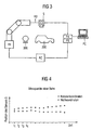
- Fig. 3 is a schematic representation of the embodiment of the present invention for measuring a measurement object 200.
- the embodiment of the present invention utilizes a robot R1 with a very high repeatability by a compensation of internal and / or external influences based on repeated measurement of the reference body 300. Then you just need once precisely determine the path of the sensor S.
- the web is deposited in a suitable form in a memory and retrieves it for later measurement of a measurement object 200 again from the memory for the processing of the measurement data of the sensor S, the sensor S is performed for each measurement object 200 along the same path.
- the web is suitably recorded in a representation in the world coordinate as well as in the robot coordinate of the robot R1, and this data pair as in FIG Fig. 4 saved as a curve.
- the robot controller RC can output at any time where the sensor S is located in the robot coordinate system.
- the sensor processing device PA queries the path of the robot controller RC for each measuring point of the sensor S and translates it into the world coordinate system by means of a previously determined table. This curve can consist of discrete points or represent a functional, which is obtained by a suitable interpolation of the measuring points.
- An indispensable prerequisite for the method according to the invention is that the web is precisely repeated.
- a compensation step is carried out regularly, in the case of this embodiment prior to the measurement of each further measurement object 200.
- the reference body 300 serves this purpose.
- the reference body 300 is measured regularly.
- the reference body 300 is constructed so that its dimensions do not change. If a different point cloud is obtained during a measurement of the reference body than in an original measurement, this is solely attributed to changes in the kinematics of the robot R1.
- the kinematics of the robot are subject to so-called internal influences, e.g. Wear of the joints, as well as external influences, such as Ambient temperature changes affecting the dimensions of the robot R1.
- the robot controller RC is adapted so that the sensor S is again guided along the original path and the original point cloud of the reference body results.
- the adaptation of the robot controller RC thus also compensates for the changes in the kinematics of the robot R1 to the path around the measurement object 200.
- Fig. 5 are shown schematically as a flowchart steps of the embodiment of the present invention for robotically measuring a measurement object 200.
- an initialization phase T1 to be explained, an actual path of the robot-guided sensor S is determined and stored. Thereafter, the calibration device K1, K2, KC for determining the paths of the sensor S can be dismantled T2 and used for other robots. Since this calibration device is very expensive, it is worth reusing it.
- the measurement phase T3, within which the kinematic compensation step is first executed, is performed that the sensor S is always guided along the same stored actual web. Then, a measurement object 200 is measured T5 and then a next measurement object 200 is provided for measurement T6.
- step T5 each point of the actual path is approached in a sequence, the world coordinates are loaded from the memory for each point A of the actual path and a measurement point of the measurement object is recorded at point A, so that the point cloud of the measurement object 200 is obtained ,
- Fig. 6 schematically the method for determining and setting the web is shown as a flow chart, which corresponds to an initialization phase T1.
- the path is transferred to the robot coordinate system T12. Fluctuations in the hand-held sensor S recorded during manual guidance can be reduced by smoothing the web in step T12. Otherwise, the robot-guided track should correspond to the recorded manual track, as far as the kinematics and the structure of the robot permit.
- the sensor S is guided robotically and the actual path is recorded T14. This robot-controlled actual lane is stored T15. Since the robot R1 has improved repeat accuracy, this actual path is now traced in subsequent guides of the sensor by means of the robot R1 in very good agreement.
- optical sensor such as a video camera.
- present invention is not limited thereto, it can be used in addition to optical and inductive or tactile sensors.
- the possibility of an absolute positionability of the robot is particularly advantageous.
Landscapes
- Engineering & Computer Science (AREA)
- Robotics (AREA)
- Mechanical Engineering (AREA)
- Physics & Mathematics (AREA)
- General Physics & Mathematics (AREA)
- Manipulator (AREA)
- Length Measuring Devices With Unspecified Measuring Means (AREA)
Description
- Die vorliegende Erfindung betrifft ein Verfahren zur robotergestützten Vermessung von Objekten und betrifft eine Vorrichtung zur Ausführung des Verfahrens der robotergestützten Vermessung von Objekten.
- Obwohl das Verfahren für beliebige Roboter zur Vermessung anwendbar ist, wird die vorliegende Erfindung sowie die ihr zugrunde liegende Problematik in Bezug auf einen Industrieroboter zur Vermessung von Fahrzeugkarosserieteilen erläutert.
- Allgemein kommen für die Vermessung von Bauteilen, insbesondere Fahrzeugkarosserieteilen, in der Automobilindustrie zunehmend Industrieroboter zum Einsatz. Diese Roboter sind mit einem beispielsweise optischen Messsystem ausgestattet und können sehr flexibel für komplizierte Messaufgaben, insbesondere an schwer zugänglichen Stellen, eingesetzt werden.
- Die Vermessung eines Objekts mit einem bewegten Sensor erfordert, eine Festlegung der Bahnen des Sensors, um aus der Bahn und den Bilddaten des Sensors eine Punktewolke des Messobjekts in einem Weltkoordinatensystem zu erhalten. Deshalb geht in die Qualität der Vermessung des Objekts auch die Qualität der Vermessung bzw. der Reproduzierbarkeit der Bahnen des Sensors ein.
- In
EP 0 963 816 A2 ist ein Verfahren zur Kompensation von kinematischen Veränderungen eines Roboters beschrieben. Dazu wird der Roboter bei Inbetriebnahme in eine ausreichende Anzahl an unterschiedlichen erstmaliger Posen gefahren und in diesen durch externe Kameras vermessen. Im laufenden Betrieb fährt der Roboter diese Posen erneut an und aus einer erfassten Abweichung der nun angefahrenen Posen zu den erstmaligen Posen wird ein Korrekturwert für ein Robotersteuerungsmodell bestimmt. - In
DE 102 35 905 A1 ist ein Verfahren zur Montage eines Werkstückes an einem Objekt mittels eines Roboters beschrieben. An einer Referenzposition wird der Roboter mittels eines Meßsystems relativ zum Weltkoordinatensystem bestimmt und mit einem Bildverarbeitungssystem erfasst. In einer Betriebsphase wird eine Abweichung des Roboters von der Referenzposition mit Hilfe des Bildverarbeitungssystems bestimmt. Basierend auf der Abweichung wird ein Korrekturvektor zur Führung des Roboters zu der Referenzposition bestimmt und an eine Robotersteuerung übermittelt. - In
DE 100 48 952 A1 ist ein Verfahren zur Aufnahme von zunächst unbekannten Arbeitspunkten mittels einer Tasteinrichtung und mit mehreren Sensoren, welche an einem zu programmierenden Ort angebracht wird und einen Entfernungsvektor zur momentanen Position einer Referenzeinheit an dem Roboterwerkzeug bestimmt. - Die
EP 1 076 221 A2 beschreibt eine Vorrichtung zur robotergesteuerten Vermessung von Objekten. Die Vorrichtung besteht aus einem Roboter mit einer Robotersteuerung, um einen berührungslosen Sensor entlang der Oberfläche eines Objektes zu führen, welcher Bilddaten der Oberfläche des Objektes aufnimmt. Eine Positionsbestimmungseinrichtung bestimmt die Position des berührungslosen Sensors. Ein Synchronisationssignal wird sowohl an den berührungslosen Sensor wie auch die Positionserfassungseinrichtung gesandt, so dass der berührungslose Sensor Bilddaten zu jedem Synchronisationssignal erstellt und die Positionsbestimmungseinrichtung zu jedem Synchronisationssignal die Position des berührungslosen Sensors bestimmt. Eine Bildverarbeitungseinrichtung ermittelt aus den beiden erstellten Datensätzen die Form des Messobjektes. - Der Nachteil der vorgestellten Vorrichtung ist, dass die Positionsbestimmungseinrichtung permanent benötigt wird. Dies ist unter dem Gesichtspunkts des Platzbedarfs wie auch der Kosten der Herstellung einer solchen Vorrichtung nachteilig.
- Die Aufgabe der vorliegenden Erfindung besteht darin, ein Verfahren zur robotergestützten Vermessung von Objekten zu schaffen, welche die Positionserfassungseinrichtung nicht permanent benötigt, sowie eine Vorrichtung zur Ausführung des genannten Verfahrens.
- Erfindungsgemäß wird diese Aufgabe durch das im Anspruch 1 angegebene Verfahren gelöst.
- Das erfindungsgemäße Verfahren weist gegenüber dem bekannten Lösungsansatz den Vorteil auf, dass nur einmal die Absolutkoordinaten der Bahnen des robotergeführten Sensors festgelegt werde müssen. Danach wiederholt der Roboter exakt dieselben Bahnen.
- Damit ergeben sich überall dort neue Einsatzgebiete der robotergestützten Vermessung, wo bisher aufgrund von Positionierungsfehlern des Roboters die erforderliche Genauigkeit der Vermessung nicht erreicht werden konnte und/oder wegen der Kosten und dem Platzbedarf keine stationär installierte Positionserfassungseinrichtung verwendet werden.
- Die der vorliegenden Erfindung zugrunde liegende Idee besteht darin, dass ein Robotersystem mit einer hohen Wiederholgenauigkeit verwendet wird und die Bahnen des Sensors nur einmalig in einem Weltkoordinatensystem vermessen wird. Dazu werden die notwendigen Bahnen zur Vermessung festgelegt und in die Robotersteuerung eingegeben. Diese führt diese Bahnen aus, welche dann in einem Weltkoordinatensystem vermessen werden. Die Bahn in den Weltkoordinaten wird in einer zweckmäßigen Weise in einer geeigneten Einrichtung so abgespeichert, dass zu jeder Pose des Roboters, während der Sensor die Bahn entlang geführt wird, die Koordinaten des Sensors in dem Weltkoordinatensystem aus dieser Einrichtung auslesbar sind. Für das Führen des Sensors wird ein Roboter verwendet, dessen Wiederholgenauigkeit aufgrund einer Kompensation von externen und/oder internen Einflüssen verbessert ist. Dazu wird nach einem oder mehreren Messungen eine Kompensation durchgeführt. Eine Sensorauswertungsvorrichtung bestimmt aus der abgespeicherten Bahn in den Weltkoordinaten und den Bilddaten des Sensors eine Punktewolke des Messobjekts.
- In den Unteransprüchen finden sich vorteilhafte Weiterbildungen und Verbesserungen des in Anspruch 1 angegebenen Verfahrens.
- Gemäß einer bevorzugten Weiterbildung wird jedes Mal vor oder nach der Vermessung ein Messobjektes eine Kompensation der internen und/oder externen Einflüssen durchgeführt. Damit wird jedes Messobjekt mit gleichbleibender Genauigkeit vermessen.
- Gemäß einer bevorzugten Weiterbildung erfolgt das Festlegen der Bahnen und/oder das Bestimmen der Ist-Bahnen des an dem Roboter geführten Sensors durch eine externe Kalibrierungseinrichtung.
- Gemäß einer bevorzugten Weiterbildung vermisst die externe Kalibrierungseinrichtung die Positionen von Markierungen, welche fest oder lösbar angebracht an dem Sensor angebracht sind.
- Gemäß einer bevorzugten Weiterbildung wird zum Festlegen der Bahnen des Sensors, das Messobjekt vermessen, indem der Sensor manuell geführt wird und die manuell geführte Bahn des Sensors während des Vermessens mit der externen Positionsbestimmungseinrichtung bestimmt wird. Damit lassen sich langwierige Lernphasen für die Roboterführung einsparen.
- Gemäß einer bevorzugten Weiterbildung wird zum Festlegen der Bahnen des Sensors, der Sensor per Hand abgekoppelt vom Roboter oder der Sensor gekoppelt an den Roboters mit einer manuellen Steuerung um das Messobjekt geführt.
- Erfindungsgemäß wird zum Kompensieren von externen und/oder internen Einflüssen zur Erhöhung der Wiederholgenauigkeit ein Referenzkörper mit dem mit dem Roboter geführten Sensor vermessen. Aus den Abweichungen einer gemessenen Punktewolke zu einer vorhergehenden gemessenen Punktewolke des Referenzkörpers wird eine Anpassung der Robotersteuerung derart vorgenommen, dass die Änderungen der Kinematik des Roboters kompensiert werden, welche zu den verschiedenen Punktewolken führten. Vorteilhaft ist, dass mit diesem Verfahren eine hohe Wiederholgenauigkeit erreicht wird, ohne dass ein externer Sensor benötigt wird.
- Gemäß einer bevorzugten Weiterbildung wird zum Bestimmen der Bahnen des an mit dem Roboter geführten Sensors und/oder Festlegen der Bahnen des Sensors um den Referenzkörper, der Sensor per Hand abgekoppelt vom Roboter oder der Sensor gekoppelt an den Roboter mit einer manuellen Steuerung um den Referenzkörper geführt und die Ist-Bahnen mit der externen Positionsbestimmungseinrichtung aufgezeichnet. Damit lassen sich langwierige Lernphasen für die Roboterführung einsparen.
- Gemäß einer bevorzugten Weiterbildung werden die bestimmten Ist-Bahnen des Sensors an die festgelegten Bahnen des Sensors angepasst. Hierbei müssen die Bahnen nicht exakt übernommen werden, sondern es sind auch Glättungen der handgeführten Bahnen möglich.
- Gemäß einer bevorzugten Weiterbildung ist der Roboter gegen den externen Einfluss von Temperaturschwankungen auf seine Wiederholgenauigkeit kompensiert. Damit lassen sich vorteilhafter Weise Driften in der Positionierung kompensieren, welche auf Grund der Eigenerwärmung des Roboters entstehen.
- Ausführungsbeispiele der Erfindung sind in den Zeichnungen dargestellt und in der nachfolgenden Beschreibung näher erläutert.
- Es zeigen:
- Fig. 1
- eine schematische Darstellung einer Vorrichtung zum Ausführen einer Initialisierungsphase einer Ausfüh- rungsform der vorliegenden Erfindung;
- Fig. 2
- eine schematische Darstellung einer Vorrichtung zum robotergestützten Vermessung;
- Fig. 3
- eine schematische Darstellung der Ausführungsform der vorliegenden Erfindung;
- Fig. 4
- eine schematische Darstellung zur Erläuterung einer Problematik des Zuordnens der Positionen einer Bahn des Sensors S in Roboterkoordinaten zu den realen Weltkoordinaten für jeden Messpunkt der Punktewolke des Messobjekts;
- Fig. 5
- eine schematische Darstellung als Flussdiagramm der Schritte der Ausführungsform der vorliegenden Erfin- dung zum robotergestützten Vermessen eines Messob- jekts; und
- Fig. 6
- eine schematische Darstellung als Flussdiagramm der Schritte einer Ausführungsform einer Initialisierungs- phase.
- In den Figuren bezeichnen gleiche Bezugszeichen gleiche oder funktionsgleiche Komponenten.
- In
Fig. 1 ist eine schematische Darstellung einer Vorrichtung zum Ausführen einer Initialisierungsphase einer Ausführungsform der vorliegenden Erfindung, mit einem Messobjekt 200; einem Referenzkörper 300; einem berührungslosen Sensor S; mit Markierungen M, welche an dem Sensor S befestigt sind; einer Sensorverarbeitungseinrichtung PA; einer Sensorsteuerungseinrichtung PB; einem Ausgabeterminal PC; einer Kalibrationsvorrichtung bestehend aus einer oder mehreren Kameras K1, K2 und einer Kamerasteuerungs- und Auswertungseinrichtung KC. Der Sensor S wird manuell um das Messobjekt 200 und den Referenzkörper 300 geführt. Die Kalibrierungsvorrichtung K1, K2, KC vermisst die Positionen der Markierungen M in einem Weltkoordinatensystem. Aus den Positionen der Markierungen M, welche an dem Sensor S befestigt sind, wird die Position und Orientierung des Sensors S, also die Bahn des Sensors S bestimmt. Die Bilddaten des Sensors S werden zusammen mit der Bahn des Sensors S von der Sensorverarbeitungsvorrichtung PA verarbeitet und die errechnete Punktewolke des Messobjekts 200 und des Referenzkörpers 300 sofort auf dem Ausgabeterminal PC ausgegeben. Dies ermöglicht eine intuitive Bedienung des Sensors S, da der Benutzer unmittelbar erkennen kann, welche Auswirkungen die handgeführte Bahn des Sensors S auf die Erfassung der Punktewolke des Messobjekts 200 und des Referenzkörpers 300 hat. Die handgeführte Bahn wird abgespeichert und dient später als Vorlage für eine robotergeführte Bahn. - Die Verarbeitung der Bilddaten des Sensors S mit der Bahn des Sensors S erfolgt derart, dass zu jedem Messpunkt der Bilddaten die Position und Orientierung des Sensors S zugeordnet werden, die der Sensor S zur Aufnahme des Messpunktes einnahm. Die Messpunkte sind in dem lokalen Koordinatensystem des Sensors S aufgenommen, da dieses lokale Koordinatensystem mit dem Sensor bewegt wird, ist eine Transformation aller Messpunkte aus dem lokalen in das feste Weltkoordinatensystem notwendig. Diese Transformation zwischen den beiden Koordinatensystemen basiert auf der Bahn des Sensors S und grundlegenden geometrischen Beziehungen.
-
Fig. 2 zeigt eine schematische Darstellung einer Vorrichtung zum robotergestützten Vermessung des Messobjektes 200 und des Referenzkörpers 300 mit dem Roboter R1, an dessen Roboterflansch R3 der Sensors S befestigt ist und der Robotersteuerung RC. Die Robotersteuerung RC steuert den Roboterflansch R3 entlang einer Bahn, welche in der Robotersteuerung RC im Roboterkoordinatensystem festgelegt ist. Für die Verarbeitung der Bilddaten des Sensors S wird wie im Fall der manuellen Führung die Bahn des Sensors S benötigt. Dazu bestimmt die Positionsbestimmungseinrichtung K1, K2, KC die Bahn des Sensors S. - Die Bahn des Sensors S zum Vermessen eines Messobjekts 200 und eines Referenzkörpers 300 kann auf mehrere Weisen gewonnen werden. Ein erfindungsgemäßes Verfahren ist den Sensor S per Hand um das Messobjekt 200 und das Referenzkörper 300 zu führen, wie dies in
Fig. 1 dargestellt ist und die handgeführte Bahn dann als Vorlage für eine robotergeführte Bahn zu nutzen. Dazu wird die handgeführte Bahn in eine Darstellung im Roboterkoordinatensystem übertragen und die Darstellung in die Robotersteuerung RC eingeben. Die handgeführte Bahn kann noch korrigiert werden, um z.B. Schwankungen des handgeführten Sensors S, welches bei der manuellen Führung mit aufgezeichnet wurden, durch Glätten der Bahn zu reduzieren. Ansonsten soll die robotergeführten Bahn, soweit die Kinematik und der Aufbau des Roboters dies erlauben, der aufgezeichneten handgeführten Bahn entsprechen. - Es gibt mehrere Möglichkeiten zu den Bilddaten des Sensors S die korrespondierende Bahn des robotergeführten Sensors S zu bestimmen. Eine Methode ist, zu jedem Messpunkt die Position und Orientierung des Sensors S zu bestimmen. Dies erfordert aber die Positionsbestimmungseinrichtung K1, K2, KC stationär zu installieren. Eine zweite Methode ist die Positioniergenauigkeit des Roboters R1 zu nützen und den Sensor S entlang einer vorbestimmten Bahn präzise zu führen. Dies erfordert eine absolute Positioniergenauigkeit des Roboters, welche Roboter nach heutigem Stand der Technik nicht in ausreichendem Maße erreichen. Das erfindungsgemäße Verfahren ermöglicht eine dritte Variante.
- In
Fig. 3 ist eine schematische Darstellung der Ausführungsform der vorliegenden Erfindung zum Vermessung eines Messobjektes 200. Die Ausführungsform der vorliegenden Erfindung nützt einen Roboter R1 mit einer sehr hohen Wiederholgenauigkeit durch eine Kompensation interner und/oder externer Einflüsse basierend auf wiederholtem Vermessen des Referenzkörpers 300. Dann muss man nur einmal präzise die Bahn des Sensors S bestimmen. Die Bahn legt man in geeigneter Form in einem Speicher ab und ruft sie für eine spätere Vermessung eines Messobjekts 200 wieder aus dem Speicher für die Verarbeitung der Messdaten des Sensors S ab, wobei der Sensor S für jedes Messobjekt 200 entlang der selben Bahn geführt wird. - Eine Zuordnung der Position und Orientierung des Sensors S zu den Messpunkten einer Bahn erfolgt mittels der Robotersteuerung RC. Dazu wird in der Ausführungsform der vorliegenden Erfindung die Bahn in einer Darstellung im Weltkoordinaten als auch im Roboterkoordinaten des Roboters R1 geeignet aufgezeichnet, und dieses Datenpaar wie in
Fig. 4 als Kurve dargestellt abgespeichert. Die Robotersteuerung RC kann zu jedem Zeitpunkt ausgeben, wo sich der Sensor S im Roboterkoordinatensystem befindet. Die Sensorverarbeitungsvorrichtung PA fragt zu jedem Messpunkt des Sensors S die Bahn der Robotersteuerung RC ab und übersetzt sie mittels einer zuvor bestimmten Tabelle in das Weltkoordinatensystem. Diese Kurve kann aus diskreten Punkten bestehen oder ein Funktional darstellen, das durch eine geeignete Interpolation der Messpunkte gewonnen wird. - Eine unabdingbare Vorraussetzung für das erfindungsgemäße Verfahren ist, dass die Bahn präzise wiederholt wird. Dazu wird regelmäßig ein Kompensationsschritt ausgeführt, im Fall dieser Ausführungsform vor der Vermessung jedes weiteren Messobjekts 200. Dazu dient der Referenzkörper 300. Der Referenzkörper 300 wird regelmäßig vermessen. Der Referenzkörper 300 ist so aufgebaut, dass sich seine Abmessungen nicht verändern. Wird bei einer Vermessung des Referenzkörpers eine andere Punktwolke erhalten, als in einer ursprünglichen Vermessung, wird dies einzig auf Änderungen der Kinematik des Roboters R1 zurückgeführt. Die Kinematik des Roboters unterliegt sogenannten internen Einflüssen, wie z.B. Abnutzung der Gelenke, als auch externen Einflüssen, wie z.B. Veränderungen der Umgebungstemperatur, welche die Abmessungen des Roboters R1 beeinflussen. Wird eine Änderung der Kinematik detektiert, wird die Robotersteuerung RC so anpasst, dass der Sensor S wieder entlang der ursprünglichen Bahn geführt wird und die ursprüngliche Punktewolke des Referenzkörpers resultiert. Die Anpassung der Robotersteuerung RC kompensiert damit auch die Änderungen der Kinematik des Roboters R1 auf die Bahn um das Messobjekt 200.
- In
Fig. 5 sind schematisch als Flussdiagramm Schritte der Ausführungsform der vorliegenden Erfindung zum robotergestützten Vermessen eines Messobjekts 200 dargestellt. In einem noch zu erläuterndem Initialisierungsphase T1 wird eine Ist-Bahn des robotergeführten Sensors S bestimmt und abgespeichert. Danach kann die Kalibrierungsvorrichtung K1, K2, KC zum Bestimmen der Bahnen des Sensors S abgebaut werden T2 und für weitere Roboter verwendet werden. Da diese Kalibrierungsvorrichtung sehr teuer ist, lohnt sich deren Mehrfachverwendung. Danach erfolgt die Messphase T3, innerhalb derer zuerst der Kinematikkompensationsschritt ausgeführt wird, so dass der Sensor S immer entlang derselben abgespeicherten Ist-Bahn geführt wird. Dann wird ein Messobjekt 200 vermessen T5 und dann ein nächstes Messobjekt 200 zum Vermessen bereitgestellt T6. Während des Schrittes T5 wird in einer Abfolge jeder Punkt der Ist-Bahn angefahren, zu jedem Punkt A der Ist-Bahn die Weltkoordinaten aus dem Speicher geladen und an dem Punkt A ein Messpunkt des Messobjekts aufgenommen, so dass die Punktewolke des Messobjekts 200 erhalten wird. - In
Fig. 6 ist schematisch das Verfahren zum Bestimmen und Festlegen der Bahn als Flussdiagramm dargestellt, welches einer Initialisierungsphase T1 entspricht. Nach einem manuellem Führen des Sensors T10 und Aufzeichnen der Bahn des Sensors mit der Kalibrierungseinrichtung K1, K2, KC T11 wird die Bahn in das Roboterkoordinatensystem übertragen T12. Schwankungen des handgeführten Sensors S, welches bei der manuellen Führung mit aufgezeichnet wurde, kann durch Glätten der Bahn im Schritt T12 reduziert werden. Ansonsten soll die robotergeführte Bahn, soweit die Kinematik und der Aufbau des Roboters dies erlauben, der aufgezeichneten manuellen Bahn entsprechen. Im Schritt T13 wird der Sensor S robotergestützt geführt und die Ist-Bahn aufgezeichnet T14. Diese robotergeführte Ist-Bahn wird abgespeichert T15. Da der Roboter R1 eine verbesserte Wiederholgenauigkeit aufweist, wird diese Ist-Bahn nun bei nachfolgenden Führungen des Sensors mittels des Roboters R1 in sehr guter Übereinstimmung nachgefahren. - Obwohl die vorliegende Erfindung vorstehend anhand eines bevorzugten Ausführungsbeispiele beschrieben wurde, ist sie darauf nicht beschränkt, sondern auf vielfältige Art und Weise modifizierbar.
- Die Beschreibung suggeriert die Verwendung eines optischen Sensors z.B. einer Videokamera. Die vorliegende Erfindung ist darauf nicht beschränkt, es können neben optischen auch induktive oder taktile Sensoren verwendet werden. Für die beiden letztgenannten Sensoren ist besonders die Möglichkeit einer absoluten Positionierbarkeit des Roboters von Vorteil.
-
- 200
- Messobjekt
- 300
- Referenzkörper
- S
- Sensor
- PA
- Sensorauswertungseinrichtung für S
- PB
- Sensorsteuerungseinrichtung für S
- PC
- Ausgabeterminal
- M
- Markierungen
- K1,K2
- Kameras
- KC
- Kamerasteuerung- und Auswertungseinrichtungen
- R1
- Roboter
- R3
- Roboterflansch
- RC
- Robotersteuerung
Claims (8)
- Verfahren zur robotergestützten Vermessung von Messobjekten (200) mit den Schritten:a) Festlegen der Bahnen eines Sensors (S) in einem Weltkoordinatensystem, welche zur Vermessung eines Objektes (200) notwendig sind;b) Übertragen der Bahnen in eine Darstellung in einem Roboterkoordinatensystem eines Roboters (R1);c) Bereitstellen einer externen Kalibrierungseinrichtung (KC, K1, K2);d) Bestimmen der Ist-Bahnen des an dem Roboter (R1) geführten Sensors (S) in einem Weltkoordinatensystem mit der externen Kalibrierungseinrichtung (KC, K1, K2) und Aufzeichnen einer Tabelle mit den Ist-Bahnen und entsprechenden Bahnen;e) robotergestütztes Vermessen einer Mehrzahl weiterer Messobjekte unter Verwendung des Roboters (R1) entlang der Ist-Bahnen wobei die Position und Orientierung des Sensors (S) in den Roboterkoordinaten zu jedem Messpunkt des Sensors (S) abgefragt und die Position und Orientierung in dem Roboterkoordinatensystem mittels der Tabelle in Weltkoordinaten übertragen werden;f) wobei nach einer vorbestimmten Anzahl an Messvorgängen zum Kompensieren von externen und/oder internen Einflüssen zur Erhöhung der Wiederholgenauigkeit ein Referenzkörper (300) mit dem mit dem Roboter (R1) geführten Sensor (S) vermessen wird, und aus Abweichungen einer gemessenen Punktewolke zu einer vorhergehenden gemessenen Punktewolke des Referenzkörpers (300) eine Anpassung einer Robotersteuerung (RC) derart vorgenommen wird, dass die Änderungen der Kinematik des Roboters (R1) kompensiert werden, welche zu den verschiedenen Punktewolken führten; undwobei die Schritte a) bis d) im Rahmen einer Initialisierungsphase und die Schritte e) und f) mehrfach im Rahmen einer Messphase durchgeführt werden und die Kalibrierungseinrichtung nach Beendigung der Initialisierungsphase entfernt werden kann.
- Verfahren nach Anspruch 1, wobei die vorbestimmte Anzahl an Messvorgängen des Schrittes e) 1 ist.
- Verfahren nach Anspruch 1 und 2, wobei das Festlegen der Bahnen des an dem Roboter geführten Sensors (S) durch die externe Kalibrierungseinrichtung erreicht wird (KC, K1, K2).
- Verfahren nach Anspruch 3, wobei die externe Kalibrierungseinrichtung (KC, K1, K2) die Positionen von Markierungen (M) vermisst, welche fest oder lösbar angebracht an dem Sensor (S) angebracht sind.
- Verfahren nach Anspruch 3 oder 4, wobei zum Festlegen der Bahnen des Sensors (S), das Messobjekt (200) vermessen wird, indem der Sensor (S) manuell geführt wird und die manuell geführte Bahnen des Sensors (S) während des Vermessens mit der externen Kalibrierungseinrichtung bestimmt wird.
- Verfahren nach einem vorhergehenden Ansprüche, wobei zum Festlegen der Bahnen des Sensors (S) der Sensor (S) per Hand abgekoppelt vom Roboter (R1) oder per manueller Steuerung des Roboters (R1) um das Messobjekt (200) geführt wird.
- Verfahren nach einem vorhergehenden Ansprüche, wobei zum Bestimmen der Bahnen des mit dem Roboter (R) geführten Sensors (S) und/oder Festlegen der Bahnen des Sensors (S) um den Referenzkörper (300), der Sensor (S) per Hand abgekoppelt vom Roboter (R1) oder per manueller Steuerung des Roboters (R1) um den Referenzkörper (300) geführt wird und die Ist-Bahnen mit der externen Positionsbestimmungseinrichtung (K1, K2, KC) aufgezeichnet werden.
- Verfahren nach einem der vorhergehenden Ansprüche, wobei das Anpassen der bestimmten Ist-Bahnen des Sensors (S) an die festgelegten Bahnen des Sensors (S) durchgeführt wird.
Applications Claiming Priority (2)
| Application Number | Priority Date | Filing Date | Title |
|---|---|---|---|
| DE102004024378A DE102004024378B4 (de) | 2004-05-17 | 2004-05-17 | Verfahren zur robotergestützten Vermessung von Objekten |
| PCT/EP2005/004921 WO2005115700A1 (de) | 2004-05-17 | 2005-05-06 | Verfahren zur robotergestützen vermessung von messobjekten |
Publications (2)
| Publication Number | Publication Date |
|---|---|
| EP1750909A1 EP1750909A1 (de) | 2007-02-14 |
| EP1750909B1 true EP1750909B1 (de) | 2009-07-22 |
Family
ID=34972334
Family Applications (1)
| Application Number | Title | Priority Date | Filing Date |
|---|---|---|---|
| EP05759568A Expired - Lifetime EP1750909B1 (de) | 2004-05-17 | 2005-05-06 | Verfahren zur robotergestützten vermessung von messobjekten |
Country Status (5)
| Country | Link |
|---|---|
| US (2) | US20090099690A1 (de) |
| EP (1) | EP1750909B1 (de) |
| CN (1) | CN100484725C (de) |
| DE (2) | DE102004024378B4 (de) |
| WO (1) | WO2005115700A1 (de) |
Families Citing this family (21)
| Publication number | Priority date | Publication date | Assignee | Title |
|---|---|---|---|---|
| DE102007026956A1 (de) * | 2007-06-12 | 2008-12-18 | Kuka Innotec Gmbh | Verfahren und System zum Roboter geführten Depalettieren von Reifen |
| DE202008011332U1 (de) * | 2008-08-26 | 2010-02-11 | Dmg Microset Gmbh | Vorrichtung zum Vermessen und/oder Einstellen eines Werkzeugs |
| DE102008060052A1 (de) * | 2008-12-02 | 2010-06-17 | Kuka Roboter Gmbh | Verfahren und Vorrichtung zur Kompensation einer kinematischen Abweichung |
| DE102009041734B4 (de) | 2009-09-16 | 2023-11-02 | Kuka Roboter Gmbh | Vermessung eines Manipulators |
| WO2011140704A1 (en) * | 2010-05-11 | 2011-11-17 | Abb Research Ltd. | Apparatus, method, program and recording medium for robot offline teaching |
| DE102010050138B4 (de) | 2010-11-03 | 2023-07-06 | Gienanth Gmbh | Vorrichtung zur Erzeugung einer Markierung an einem zu bearbeitenden Werkstück |
| KR101337650B1 (ko) | 2011-11-02 | 2013-12-05 | 삼성중공업 주식회사 | 실시간 위빙 모션 제어 장치 및 그 방법 |
| CN105423919B (zh) * | 2015-12-18 | 2018-01-02 | 重庆德新机器人检测中心有限公司 | 利用固液相快速转换材料投影成像检测机器人精度的方法 |
| JP6430986B2 (ja) * | 2016-03-25 | 2018-11-28 | ファナック株式会社 | ロボットを用いた位置決め装置 |
| JP6527178B2 (ja) | 2017-01-12 | 2019-06-05 | ファナック株式会社 | 視覚センサのキャリブレーション装置、方法及びプログラム |
| DE102017107593B4 (de) * | 2017-04-07 | 2023-04-27 | Deutsches Zentrum für Luft- und Raumfahrt e.V. | Verfahren zum Bestimmen unbekannter Transformationen |
| DE102017212261A1 (de) * | 2017-07-18 | 2019-01-24 | Bayerische Motoren Werke Aktiengesellschaft | Messsystem und Verfahren zum Einmessen mindestens eines automatischen, insbesondere mehrachsigen, Manipulators |
| CN108195354A (zh) * | 2017-12-21 | 2018-06-22 | 长沙长泰机器人有限公司 | 一种基于机器人的车辆定位方法和车辆定位系统 |
| EP3650740B1 (de) * | 2018-11-06 | 2020-12-30 | Sick Ag | Sicherheitssystem und verfahren zum überwachen einer maschine |
| CN109490830B (zh) * | 2018-11-23 | 2024-08-02 | 北京天智航医疗科技股份有限公司 | 手术机器人定位系统精度检测方法及检测装置 |
| US11911914B2 (en) * | 2019-01-28 | 2024-02-27 | Cognex Corporation | System and method for automatic hand-eye calibration of vision system for robot motion |
| DE102019102927B4 (de) | 2019-02-06 | 2023-02-23 | Carl Zeiss Industrielle Messtechnik Gmbh | Verfahren und Vorrichtung zum Bestimmen von dimensionalen und/oder geometrischen Eigenschaften eines Messobjekts |
| US20220176564A1 (en) | 2020-12-04 | 2022-06-09 | GM Global Technology Operations LLC | Accurate position control for fixtureless assembly |
| DE102022118260B3 (de) | 2022-07-21 | 2023-10-05 | Dürr Assembly Products GmbH | Verfahren zur Kalibrierung und/oder Justierung des intrinsischen Koordinatensystems eines Fahrzeugaggregats relativ zu einem Koordinatensystem des Fahrzeugs und Fahrzeugprüfstand zur Durchführung des Verfahrens |
| DE102023101972A1 (de) * | 2023-01-27 | 2024-08-01 | Matthias Krebs | Sensorsystem und Verfahren zum Betrieb eines Sensorsystems |
| WO2025144875A1 (en) * | 2023-12-27 | 2025-07-03 | Bright Machines, Inc. | Iterative robot-vision calibration |
Family Cites Families (16)
| Publication number | Priority date | Publication date | Assignee | Title |
|---|---|---|---|---|
| US4788440A (en) * | 1981-05-11 | 1988-11-29 | Diffracto Ltd. | Electro-optical systems for control of robots, manipulator arms and coordinate measuring machines |
| US4753569A (en) * | 1982-12-28 | 1988-06-28 | Diffracto, Ltd. | Robot calibration |
| US4754415A (en) * | 1984-10-12 | 1988-06-28 | Diffracto Ltd. | Robotic alignment and part simulation |
| US4882527A (en) * | 1987-10-16 | 1989-11-21 | Nissan Motor Co., Ltd. | Three-dimensional measuring robot |
| US5380978A (en) * | 1991-07-12 | 1995-01-10 | Pryor; Timothy R. | Method and apparatus for assembly of car bodies and other 3-dimensional objects |
| WO1997024206A1 (en) * | 1995-12-27 | 1997-07-10 | Fanuc Ltd | Composite sensor robot system |
| DE19626459C2 (de) * | 1996-07-02 | 1999-09-02 | Kuka Schweissanlagen Gmbh | Verfahren und Vorrichtung zum Teachen eines programmgesteuerten Roboters |
| EP1040393A4 (de) * | 1997-09-04 | 2004-03-10 | Dynalog Inc | Verfahren zum eichen eines robotisierten kontrollsystems |
| DE19826395A1 (de) * | 1998-06-12 | 1999-12-23 | Amatec Gmbh | Verfahren zum Erfassen und Kompensieren von kinematischen Veränderungen eines Roboters |
| DE19931676C2 (de) * | 1999-07-08 | 2002-07-11 | Kuka Schweissanlagen Gmbh | Verfahren zum Vermessen von Werkstücken und Bearbeitungsstation |
| US6615112B1 (en) * | 1999-06-26 | 2003-09-02 | Kuka Schweissanlagen Gmbh | Method and device for calibrating robot measuring stations, manipulators and associated optical measuring devices |
| US6166811A (en) * | 1999-08-12 | 2000-12-26 | Perceptron, Inc. | Robot-based gauging system for determining three-dimensional measurement data |
| US6374158B1 (en) * | 2000-02-15 | 2002-04-16 | General Electric Company | Robotic laser pointer |
| DE10048952B4 (de) * | 2000-10-04 | 2008-08-21 | Kuka Roboter Gmbh | Verfahren und Vorrichtung zur Aufnahme unbekannter Raumpunkte in einer Arbeitszelle eines Roboters |
| CA2369845A1 (en) * | 2002-01-31 | 2003-07-31 | Braintech, Inc. | Method and apparatus for single camera 3d vision guided robotics |
| ATE531488T1 (de) * | 2002-03-04 | 2011-11-15 | Vmt Vision Machine Technic Bildverarbeitungssysteme Gmbh | Verfahren zur bestimmung der lage eines objektes und eines werkstücks im raum zur automatischen montage des werkstücks am objekt |
-
2004
- 2004-05-17 DE DE102004024378A patent/DE102004024378B4/de not_active Expired - Lifetime
-
2005
- 2005-05-06 EP EP05759568A patent/EP1750909B1/de not_active Expired - Lifetime
- 2005-05-06 US US11/720,982 patent/US20090099690A1/en not_active Abandoned
- 2005-05-06 WO PCT/EP2005/004921 patent/WO2005115700A1/de not_active Ceased
- 2005-05-06 CN CNB2005800157100A patent/CN100484725C/zh not_active Expired - Fee Related
- 2005-05-06 DE DE502005007752T patent/DE502005007752D1/de not_active Expired - Lifetime
-
2015
- 2015-11-24 US US14/950,699 patent/US9833904B2/en not_active Expired - Fee Related
Also Published As
| Publication number | Publication date |
|---|---|
| DE102004024378A1 (de) | 2005-12-15 |
| WO2005115700A1 (de) | 2005-12-08 |
| WO2005115700B1 (de) | 2006-01-19 |
| DE102004024378B4 (de) | 2009-05-20 |
| CN1953848A (zh) | 2007-04-25 |
| US20160075029A1 (en) | 2016-03-17 |
| EP1750909A1 (de) | 2007-02-14 |
| DE502005007752D1 (de) | 2009-09-03 |
| US20090099690A1 (en) | 2009-04-16 |
| CN100484725C (zh) | 2009-05-06 |
| US9833904B2 (en) | 2017-12-05 |
Similar Documents
| Publication | Publication Date | Title |
|---|---|---|
| DE102004024378B4 (de) | Verfahren zur robotergestützten Vermessung von Objekten | |
| DE102009034529B4 (de) | Automatisches Führungs- und Erkennungssystem sowie Verfahren für dieses | |
| DE102018001026B4 (de) | Robotersystem mit einer lernenden Steuerungsfunktion und lernendes Steuerungsverfahren | |
| DE19930087B4 (de) | Verfahren und Vorrichtung zur Regelung der Vorhalteposition eines Manipulators eines Handhabungsgeräts | |
| EP0963816B1 (de) | Verfahren zum Erfassen und Kompensieren von kinematischen Veränderungen eines Roboters | |
| DE102019131284B4 (de) | Robotersystem und Koordinatenumwandlungsverfahren | |
| DE19626459C2 (de) | Verfahren und Vorrichtung zum Teachen eines programmgesteuerten Roboters | |
| DE102014017307B4 (de) | Verfahren und System zum Bearbeiten eines Bauteils mit einem robotergeführten Werkzeug | |
| DE102017111543B4 (de) | Robotersteuerungsvorrichtung und ein Verfahren zur Steuerung eines Roboters | |
| DE102015109557B4 (de) | Verfahren zur Einstellung einer Prüf- oder Messposition eines berührungslos wirkenden Sensors | |
| DE10242710A1 (de) | Verfahren zum Herstellen eines Verbindungsbereiches auf einem Werkstück | |
| WO2020225350A1 (de) | Beschichtungsverfahren und entsprechende beschichtungsanlage | |
| DE202013101050U1 (de) | Führungssystem für eine Roboteranordnung | |
| DE10349361A1 (de) | Verfahren und Vorrichtung zum Positionieren eines Handhabungsgeräts | |
| DE102017003993B4 (de) | Kalibrierung eines Roboters | |
| DE10133624A1 (de) | Vorrichtung und Anordnung zur Ermittlung von korrigierten Bewegungsdaten für einen vorgegebenen Bewegungsablauf einer bewegbaren Einrichtung sowie bewegbare Einrichtung und System aus bewegbaren Einrichtungen | |
| DE112018003597T5 (de) | Greifsystem | |
| EP0256968A1 (de) | Automatisches Verfahren zur berührungslosen dreidimensionalen Vermessung von Objekten grosser Ausdehnung | |
| DE102017112454A1 (de) | Dynamisches Laser-Touch-Sensing mit dynamischem Multiroboter-User-Frame | |
| EP1120204A2 (de) | Verfahren zum Einmessen eines Industrieroboters | |
| DE102015200319A1 (de) | Einmessverfahren aus Kombination von Vorpositionierung und Handführen | |
| EP2553536B1 (de) | Verfahren zum betreiben einer mit mindestens einem roboter bestückten behandlungskabine | |
| DE102019131401B3 (de) | Kalibrierung einer Impedanzregelung eines Robotermanipulators | |
| WO2018206387A1 (de) | Roboterjustage | |
| DE112023006429T5 (de) | Steuervorrichtung, Parameterkorrekturverfahren und Programm |
Legal Events
| Date | Code | Title | Description |
|---|---|---|---|
| PUAI | Public reference made under article 153(3) epc to a published international application that has entered the european phase |
Free format text: ORIGINAL CODE: 0009012 |
|
| 17P | Request for examination filed |
Effective date: 20061018 |
|
| AK | Designated contracting states |
Kind code of ref document: A1 Designated state(s): AT BE BG CH CY CZ DE DK EE ES FI FR GB GR HU IE IS IT LI LT LU MC NL PL PT RO SE SI SK TR |
|
| RIN1 | Information on inventor provided before grant (corrected) |
Inventor name: VERL, ALEXANDER |
|
| DAX | Request for extension of the european patent (deleted) | ||
| RIN1 | Information on inventor provided before grant (corrected) |
Inventor name: VERL, ALEXANDER |
|
| GRAP | Despatch of communication of intention to grant a patent |
Free format text: ORIGINAL CODE: EPIDOSNIGR1 |
|
| GRAS | Grant fee paid |
Free format text: ORIGINAL CODE: EPIDOSNIGR3 |
|
| GRAA | (expected) grant |
Free format text: ORIGINAL CODE: 0009210 |
|
| AK | Designated contracting states |
Kind code of ref document: B1 Designated state(s): AT BE BG CH CY CZ DE DK EE ES FI FR GB GR HU IE IS IT LI LT LU MC NL PL PT RO SE SI SK TR |
|
| REG | Reference to a national code |
Ref country code: GB Ref legal event code: FG4D Free format text: NOT ENGLISH |
|
| REG | Reference to a national code |
Ref country code: CH Ref legal event code: EP |
|
| REG | Reference to a national code |
Ref country code: IE Ref legal event code: FG4D |
|
| REF | Corresponds to: |
Ref document number: 502005007752 Country of ref document: DE Date of ref document: 20090903 Kind code of ref document: P |
|
| NLV1 | Nl: lapsed or annulled due to failure to fulfill the requirements of art. 29p and 29m of the patents act | ||
| PG25 | Lapsed in a contracting state [announced via postgrant information from national office to epo] |
Ref country code: SE Free format text: LAPSE BECAUSE OF FAILURE TO SUBMIT A TRANSLATION OF THE DESCRIPTION OR TO PAY THE FEE WITHIN THE PRESCRIBED TIME-LIMIT Effective date: 20090722 Ref country code: IS Free format text: LAPSE BECAUSE OF FAILURE TO SUBMIT A TRANSLATION OF THE DESCRIPTION OR TO PAY THE FEE WITHIN THE PRESCRIBED TIME-LIMIT Effective date: 20091122 Ref country code: ES Free format text: LAPSE BECAUSE OF FAILURE TO SUBMIT A TRANSLATION OF THE DESCRIPTION OR TO PAY THE FEE WITHIN THE PRESCRIBED TIME-LIMIT Effective date: 20091102 Ref country code: LT Free format text: LAPSE BECAUSE OF FAILURE TO SUBMIT A TRANSLATION OF THE DESCRIPTION OR TO PAY THE FEE WITHIN THE PRESCRIBED TIME-LIMIT Effective date: 20090722 Ref country code: FI Free format text: LAPSE BECAUSE OF FAILURE TO SUBMIT A TRANSLATION OF THE DESCRIPTION OR TO PAY THE FEE WITHIN THE PRESCRIBED TIME-LIMIT Effective date: 20090722 |
|
| PG25 | Lapsed in a contracting state [announced via postgrant information from national office to epo] |
Ref country code: SI Free format text: LAPSE BECAUSE OF FAILURE TO SUBMIT A TRANSLATION OF THE DESCRIPTION OR TO PAY THE FEE WITHIN THE PRESCRIBED TIME-LIMIT Effective date: 20090722 Ref country code: PL Free format text: LAPSE BECAUSE OF FAILURE TO SUBMIT A TRANSLATION OF THE DESCRIPTION OR TO PAY THE FEE WITHIN THE PRESCRIBED TIME-LIMIT Effective date: 20090722 Ref country code: NL Free format text: LAPSE BECAUSE OF FAILURE TO SUBMIT A TRANSLATION OF THE DESCRIPTION OR TO PAY THE FEE WITHIN THE PRESCRIBED TIME-LIMIT Effective date: 20090722 |
|
| REG | Reference to a national code |
Ref country code: IE Ref legal event code: FD4D |
|
| PG25 | Lapsed in a contracting state [announced via postgrant information from national office to epo] |
Ref country code: PT Free format text: LAPSE BECAUSE OF FAILURE TO SUBMIT A TRANSLATION OF THE DESCRIPTION OR TO PAY THE FEE WITHIN THE PRESCRIBED TIME-LIMIT Effective date: 20091122 Ref country code: BG Free format text: LAPSE BECAUSE OF FAILURE TO SUBMIT A TRANSLATION OF THE DESCRIPTION OR TO PAY THE FEE WITHIN THE PRESCRIBED TIME-LIMIT Effective date: 20091022 |
|
| PG25 | Lapsed in a contracting state [announced via postgrant information from national office to epo] |
Ref country code: CZ Free format text: LAPSE BECAUSE OF FAILURE TO SUBMIT A TRANSLATION OF THE DESCRIPTION OR TO PAY THE FEE WITHIN THE PRESCRIBED TIME-LIMIT Effective date: 20090722 Ref country code: IE Free format text: LAPSE BECAUSE OF FAILURE TO SUBMIT A TRANSLATION OF THE DESCRIPTION OR TO PAY THE FEE WITHIN THE PRESCRIBED TIME-LIMIT Effective date: 20090722 Ref country code: EE Free format text: LAPSE BECAUSE OF FAILURE TO SUBMIT A TRANSLATION OF THE DESCRIPTION OR TO PAY THE FEE WITHIN THE PRESCRIBED TIME-LIMIT Effective date: 20090722 Ref country code: RO Free format text: LAPSE BECAUSE OF FAILURE TO SUBMIT A TRANSLATION OF THE DESCRIPTION OR TO PAY THE FEE WITHIN THE PRESCRIBED TIME-LIMIT Effective date: 20090722 Ref country code: DK Free format text: LAPSE BECAUSE OF FAILURE TO SUBMIT A TRANSLATION OF THE DESCRIPTION OR TO PAY THE FEE WITHIN THE PRESCRIBED TIME-LIMIT Effective date: 20090722 |
|
| PLBE | No opposition filed within time limit |
Free format text: ORIGINAL CODE: 0009261 |
|
| STAA | Information on the status of an ep patent application or granted ep patent |
Free format text: STATUS: NO OPPOSITION FILED WITHIN TIME LIMIT |
|
| PG25 | Lapsed in a contracting state [announced via postgrant information from national office to epo] |
Ref country code: SK Free format text: LAPSE BECAUSE OF FAILURE TO SUBMIT A TRANSLATION OF THE DESCRIPTION OR TO PAY THE FEE WITHIN THE PRESCRIBED TIME-LIMIT Effective date: 20090722 |
|
| 26N | No opposition filed |
Effective date: 20100423 |
|
| PG25 | Lapsed in a contracting state [announced via postgrant information from national office to epo] |
Ref country code: GR Free format text: LAPSE BECAUSE OF FAILURE TO SUBMIT A TRANSLATION OF THE DESCRIPTION OR TO PAY THE FEE WITHIN THE PRESCRIBED TIME-LIMIT Effective date: 20091023 |
|
| BERE | Be: lapsed |
Owner name: KUKA ROBOTER G.M.B.H. Effective date: 20100531 |
|
| PG25 | Lapsed in a contracting state [announced via postgrant information from national office to epo] |
Ref country code: MC Free format text: LAPSE BECAUSE OF NON-PAYMENT OF DUE FEES Effective date: 20100531 |
|
| REG | Reference to a national code |
Ref country code: CH Ref legal event code: PL |
|
| GBPC | Gb: european patent ceased through non-payment of renewal fee |
Effective date: 20100506 |
|
| PG25 | Lapsed in a contracting state [announced via postgrant information from national office to epo] |
Ref country code: CH Free format text: LAPSE BECAUSE OF NON-PAYMENT OF DUE FEES Effective date: 20100531 Ref country code: LI Free format text: LAPSE BECAUSE OF NON-PAYMENT OF DUE FEES Effective date: 20100531 |
|
| PG25 | Lapsed in a contracting state [announced via postgrant information from national office to epo] |
Ref country code: BE Free format text: LAPSE BECAUSE OF NON-PAYMENT OF DUE FEES Effective date: 20100531 |
|
| PG25 | Lapsed in a contracting state [announced via postgrant information from national office to epo] |
Ref country code: GB Free format text: LAPSE BECAUSE OF NON-PAYMENT OF DUE FEES Effective date: 20100506 |
|
| PG25 | Lapsed in a contracting state [announced via postgrant information from national office to epo] |
Ref country code: AT Free format text: LAPSE BECAUSE OF NON-PAYMENT OF DUE FEES Effective date: 20100506 |
|
| PG25 | Lapsed in a contracting state [announced via postgrant information from national office to epo] |
Ref country code: CY Free format text: LAPSE BECAUSE OF FAILURE TO SUBMIT A TRANSLATION OF THE DESCRIPTION OR TO PAY THE FEE WITHIN THE PRESCRIBED TIME-LIMIT Effective date: 20090722 |
|
| PG25 | Lapsed in a contracting state [announced via postgrant information from national office to epo] |
Ref country code: HU Free format text: LAPSE BECAUSE OF FAILURE TO SUBMIT A TRANSLATION OF THE DESCRIPTION OR TO PAY THE FEE WITHIN THE PRESCRIBED TIME-LIMIT Effective date: 20100123 Ref country code: LU Free format text: LAPSE BECAUSE OF NON-PAYMENT OF DUE FEES Effective date: 20100506 |
|
| PG25 | Lapsed in a contracting state [announced via postgrant information from national office to epo] |
Ref country code: TR Free format text: LAPSE BECAUSE OF FAILURE TO SUBMIT A TRANSLATION OF THE DESCRIPTION OR TO PAY THE FEE WITHIN THE PRESCRIBED TIME-LIMIT Effective date: 20090722 |
|
| REG | Reference to a national code |
Ref country code: FR Ref legal event code: PLFP Year of fee payment: 12 |
|
| REG | Reference to a national code |
Ref country code: FR Ref legal event code: PLFP Year of fee payment: 13 |
|
| REG | Reference to a national code |
Ref country code: FR Ref legal event code: PLFP Year of fee payment: 14 |
|
| REG | Reference to a national code |
Ref country code: DE Ref legal event code: R082 Ref document number: 502005007752 Country of ref document: DE Representative=s name: ISARPATENT - PATENT- UND RECHTSANWAELTE BEHNIS, DE Ref country code: DE Ref legal event code: R082 Ref document number: 502005007752 Country of ref document: DE Representative=s name: ISARPATENT - PATENT- UND RECHTSANWAELTE BARTH , DE Ref country code: DE Ref legal event code: R082 Ref document number: 502005007752 Country of ref document: DE Representative=s name: ISARPATENT - PATENTANWAELTE- UND RECHTSANWAELT, DE Ref country code: DE Ref legal event code: R081 Ref document number: 502005007752 Country of ref document: DE Owner name: KUKA DEUTSCHLAND GMBH, DE Free format text: FORMER OWNER: KUKA ROBOTER GMBH, 86165 AUGSBURG, DE |
|
| PGFP | Annual fee paid to national office [announced via postgrant information from national office to epo] |
Ref country code: FR Payment date: 20230309 Year of fee payment: 19 |
|
| P01 | Opt-out of the competence of the unified patent court (upc) registered |
Effective date: 20230528 |
|
| PGFP | Annual fee paid to national office [announced via postgrant information from national office to epo] |
Ref country code: IT Payment date: 20230412 Year of fee payment: 19 Ref country code: DE Payment date: 20230516 Year of fee payment: 19 |
|
| REG | Reference to a national code |
Ref country code: DE Ref legal event code: R119 Ref document number: 502005007752 Country of ref document: DE |
|
| PG25 | Lapsed in a contracting state [announced via postgrant information from national office to epo] |
Ref country code: DE Free format text: LAPSE BECAUSE OF NON-PAYMENT OF DUE FEES Effective date: 20241203 |
|
| PG25 | Lapsed in a contracting state [announced via postgrant information from national office to epo] |
Ref country code: FR Free format text: LAPSE BECAUSE OF NON-PAYMENT OF DUE FEES Effective date: 20240531 |
|
| PG25 | Lapsed in a contracting state [announced via postgrant information from national office to epo] |
Ref country code: IT Free format text: LAPSE BECAUSE OF NON-PAYMENT OF DUE FEES Effective date: 20240506 |