EP1751038B1 - Ensemble permettant le couplage par charniere de parties d'un transporteur - Google Patents
Ensemble permettant le couplage par charniere de parties d'un transporteur Download PDFInfo
- Publication number
- EP1751038B1 EP1751038B1 EP05749414A EP05749414A EP1751038B1 EP 1751038 B1 EP1751038 B1 EP 1751038B1 EP 05749414 A EP05749414 A EP 05749414A EP 05749414 A EP05749414 A EP 05749414A EP 1751038 B1 EP1751038 B1 EP 1751038B1
- Authority
- EP
- European Patent Office
- Prior art keywords
- hinge
- assembly
- eye
- conveyor
- row
- Prior art date
- Legal status (The legal status is an assumption and is not a legal conclusion. Google has not performed a legal analysis and makes no representation as to the accuracy of the status listed.)
- Expired - Lifetime
Links
Images





Classifications
-
- B—PERFORMING OPERATIONS; TRANSPORTING
- B65—CONVEYING; PACKING; STORING; HANDLING THIN OR FILAMENTARY MATERIAL
- B65G—TRANSPORT OR STORAGE DEVICES, e.g. CONVEYORS FOR LOADING OR TIPPING, SHOP CONVEYOR SYSTEMS OR PNEUMATIC TUBE CONVEYORS
- B65G17/00—Conveyors having an endless traction element, e.g. a chain, transmitting movement to a continuous or substantially-continuous load-carrying surface or to a series of individual load-carriers; Endless-chain conveyors in which the chains form the load-carrying surface
- B65G17/30—Details; Auxiliary devices
- B65G17/38—Chains or like traction elements; Connections between traction elements and load-carriers
- B65G17/40—Chains acting as load-carriers
-
- B—PERFORMING OPERATIONS; TRANSPORTING
- B65—CONVEYING; PACKING; STORING; HANDLING THIN OR FILAMENTARY MATERIAL
- B65G—TRANSPORT OR STORAGE DEVICES, e.g. CONVEYORS FOR LOADING OR TIPPING, SHOP CONVEYOR SYSTEMS OR PNEUMATIC TUBE CONVEYORS
- B65G17/00—Conveyors having an endless traction element, e.g. a chain, transmitting movement to a continuous or substantially-continuous load-carrying surface or to a series of individual load-carriers; Endless-chain conveyors in which the chains form the load-carrying surface
- B65G17/06—Conveyors having an endless traction element, e.g. a chain, transmitting movement to a continuous or substantially-continuous load-carrying surface or to a series of individual load-carriers; Endless-chain conveyors in which the chains form the load-carrying surface having a load-carrying surface formed by a series of interconnected, e.g. longitudinal, links, plates, or platforms
- B65G17/08—Conveyors having an endless traction element, e.g. a chain, transmitting movement to a continuous or substantially-continuous load-carrying surface or to a series of individual load-carriers; Endless-chain conveyors in which the chains form the load-carrying surface having a load-carrying surface formed by a series of interconnected, e.g. longitudinal, links, plates, or platforms the surface being formed by the traction element
-
- B—PERFORMING OPERATIONS; TRANSPORTING
- B65—CONVEYING; PACKING; STORING; HANDLING THIN OR FILAMENTARY MATERIAL
- B65G—TRANSPORT OR STORAGE DEVICES, e.g. CONVEYORS FOR LOADING OR TIPPING, SHOP CONVEYOR SYSTEMS OR PNEUMATIC TUBE CONVEYORS
- B65G2207/00—Indexing codes relating to constructional details, configuration and additional features of a handling device, e.g. Conveyors
- B65G2207/12—Chain pin retainers
Definitions
- the invention relates to an assembly for hingedly coupling parts of a conveyor, and to a hinge pin.
- a conveyor such as a conveyor mat or chain built up from modules, or a conveyor belt composed of one or more segments
- conveyor parts are coupled with the aid of hinge pins.
- a problem that occurs therein is that the hinge pins need to be locked against axial migration.
- a very advantageous assembly is known from EP 0 787 663 , which describes an assembly according to the preamble of claim 1.
- a pin with a thickened head is introduced into an end hinge eye which is somewhat out of alignment with respect to the other hinge eyes.
- pin and/or module After passing the enlarged hinge hole, pin and/or module return to their original form and the pin is axially locked between, on the one side, a locking surface of the end hinge eye in alignment with the other hinge eyes and, on the other side, the next hinge eye in coupled condition.
- a further drawback of the known conveyor is that the pin cannot extend to the side edge of the conveyor. Thus, a part of the width of the conveyor remains unused for transmitting tensile forces between the conveyor parts via the hinge pin.
- the invention contemplates an assembly for hingedly coupling parts of a conveyor with which, while maintaining the advantages, these drawbacks can be obviated.
- the invention provides an assembly for hingedly coupling parts of a conveyor, comprising a first conveyor part provided with a first row of hinge eyes spaced apart from one another with mutual interspaces with an end hinge eye located along a longitudinal edge of the conveyor part, with an end hinge hole which is somewhat out of alignment with respect to an adjacent hinge hole from the first row, further comprising a second conveyor part provided with a second row of hinge eyes which are also spaced apart from one another with mutual interspaces, such that the conveyor parts can cooperate in a coupled condition by receiving hinge eyes in corresponding interspaces, and a hinge pin provided with a central body part which extends, in coupled condition of the assembly, through hinge holes of the first row and of the second row, further provided with a thickened head which is able to pass the end hinge hole of the end hinge eye, but not the hinge hole of the next hinge eye in coupled condition, which thickened head is, in coupled condition, axially locked between the end hinge eye and the next hinge eye, characterized in that the thickened head bears a substantially cylindrical
- the hinge pin can be engaged via the end hinge eye, so that the pin is accessible from the side of the conveyor in order to be detached. This cannot only facilitate the detachment, but also allows a closed design of the conveying surface of the conveyor. Further, in coupled condition, the projection can abut a part of the wall of the end hinge eye, so that the whole width of the conveyor can be used for transmitting tensile forces.
- EP 1 500 614 which falls under Article 54(3) EPC, discloses an assembly for hingedly coupling parts of a conveyor from which the subject-matter of the present invention differs in that the diameter of the projection is constant and smaller than the diameter of the thickened head.
- US 5 645 160 discloses in Fig. 7 a hinge with a thickened head and a projection.
- US 3 726 569 discloses in Fig. 3 an insert having a wedge shaped flange.
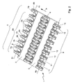
- an assembly 1 for hingedly coupling parts of a conveyor.
- the assembly comprises a first conveying part 2, a second conveying part 3 and a hinge pin 4.
- the first conveying part 2 and the second conveying part 3 are designed as successive modules of a modular conveyor mat.
- Such a conveyor mat is generally known and is usually built up from rows of one or more modules extending transverse to a conveying direction indicated by an arrow P, while rows of modules successive in conveying direction are often included in a mat so as to be staggered with respect to one another according to a brick pattern and the mat is often designed as an endless belt.
- the first conveying part 2 is provided with a first row 5 with hinge eyes 7 spaced apart with mutual interspaces 6.
- the first row 5 comprises a sub-row 5A with more centrally located hinge eyes 7A.
- the more centrally located hinge eyes 7A of the sub-row 5A are provided with hinge holes 8A in alignment with respect to one another.
- the hinge eyes 7 have identical designs and the mutual interspaces 6 between the hinge eyes 7 are equal.
- the hinge holes 8A have a substantially cylindrical design along a common centerline H 1 and have substantially the same diameter.
- the shapes of the different hinge eyes 7 and/or their mutual interspaces 6 may be unequal, and that the shapes and the dimensions of the hinge holes 8A of the successive hinge eyes may vary or may at least be chosen differently than shown in the Figure.
- the first row 5 of hinge eyes 7 further comprises an end hinge eye 7B adjacent to the sub-row 5A, which end hinge eye 7B is located on the longitudinal edge of the conveyor 1.
- the end hinge eye 7B is provided with an enlarged hinge hole 8B which is positioned somewhat out of alignment.
- the hinge hole 8B with the enlarged design has a cylindrical design with a larger diameter than the other hinge holes 8A from the first row.
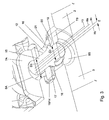
- the centerline H 2 of the enlarged hinge hole 8B is located at the same height as the centerline H 1 of the hinge holes 8A, but extends parallel to the centerline H 1 through the hinge holes 8A, shifted in conveying direction over a distance E.
- the end hinge hole 7B is provided with a locking surface 20 which is adjacent to the enlarged hinge hole 8B and extends onto the line.
- the notion "positioned in alignment” is to be understood to mean that, transverse to the conveying direction, successive hinge holes can be aligned to let a hinge pin pass freely in extended condition and that "somewhat positioned in alignment” is to be understood to mean that such a hole cannot be passed without deformation of the hinge pin and/or at least one of the conveying parts. Such a passage without deformation is then prevented in that the body part of the hinge eye surrounding the non-aligned hinge hole extends onto the line of free passage of the hinge pin.
- these notions are very well defined by the wording that the end hinge eye is in partial registry with the hinge eyes of the sub-row, and that the hinge pin is in interfering alignment with the hinge eye of the non-aligned hinge hole.
- the second conveyor part 3 is provided with a second row 9 of hinge eyes 10 which are spaced apart with mutual interspaces 11 and which are provided with hinge holes 12 aligned with respect to one another.
- the hinge eyes 10, the interspaces 11 and the hinge holes 12 are identical to the hinge eyes 7A, the interspaces 6 and the hinge holes 8A of the first conveyor part 2. So, the hinge holes 12 of the hinge eyes 10 also have a cylindrical design and are on a common centerline H 3 .
- the conveying parts 2, 3 can cooperate in coupled condition in that hinge eyes 7 of a module designed as a first conveying part, which extend in a conveying direction indicated by the open part of arrow P and reach forwards, are included in interspaces 11 between hinge eyes 10 reaching backwards of the second conveying part 3 succeeding in conveying direction and designed as a similar module.
- hinge eyes 10 of the second row are included in interspaces 6 between the hinge eyes of the first row 5.
- the hinge pin 4 is provided with a central body part 15.
- the central body part 15 extends through the hinge holes 8A of the hinge eyes 7A of sub-row 5A and through the hinge holes 13 of the hinge eyes 10 of the second row 9, such that the centerline of the hinge pin H 4 runs substantially parallel between the centerlines H 1 and H 3 of the hinge holes 8A, 12 of the cooperating hinge eyes 7A, 10.
- the hinge pin 4 is provided with a thickened head 16 which is able to pass the enlarged end hinge hole 8B of the end hinge eye 7B, but is not able to pass the next hinge eye in coupled condition.
- the hinge pin 4 is thus axially locked between the locking surface 20 of the end hinge eye 7B on the one side and the next hinge eye 14 in coupled condition, herein formed by the hinge eye 10 bounding the second row 19, on the other side.
- the thickened head 16 forms a part of the pin 4 with a larger diameter than the body part 15 of the pin 4 and has a conical design in this exemplary embodiment. As a result, at the location of the thickened head 16, the pin 4 has an enlarged diameter.
- the head 16 tapers towards the central part.
- the outer surface 17 of the cone cooperates with a corresponding cone stop surface 18 which is recessed in the hinge eye 14.
- an end surface 21 of the thickened head 16 cooperates with the locking surface 20, so that the hinge pin 4 is locked against axial migration.
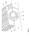
- the thickened head 16 bears a projection 19 designed with a smaller diameter compared to the head, which projection 19 extends into the hinge hole 8B of the end hinge eye 7B in coupled condition.
- the projection 19 is narrowed compared to the head 16 and reaches axially outwards from the head 16 in a direction away from the body part 15.
- the projection 19 is substantially cylindrical and has the same diameter as the body part 15 of the hinge pin 4.
- the projection 19 extends collinear with the central body part 15 of the hinge pin 4. In this manner, a part of the outer surface of the projection 19 abuts the wall of the enlarged hole 8B in the end hinge eye 7B, so that the end hinge eye 7B can also be used for transmitting tensile force.
- the hinge pin 4 extends over the whole width of the conveyor 1.
- the thickened head may of course have a different shape, for instance a sphere, a cylinder or a block shape.
- the conical shape shown in the exemplary embodiment is preferred because it can easily be introduced and further offers a good extent of locking.
- FIGs. 5-7 show that the pin 4 can be introduced in the direction indicated by the arrow Q transverse to the conveying direction.
- the central body part 15 can be threaded through the hinge holes 8, 12 up to the thickened head without bending of the pin 4.
- the pin 4 Upon reaching the thickened head 16, the pin 4 will bend slightly outwards and sidewards at the location of the head 16 ( Fig. 5 ).
- the thickened head 16 can just pass the enlarged hinge hole 8B, which is somewhat staggered.
- the pin 4 will spring back again and the thickened head 16 is locked as shown in Fig. 6 .
- the thickened head 16 In coupled condition, the thickened head 16 is thus located between the end hinge eye 7B and the next hinge eye 14. With the aid of its thickened head 16, the hinge pin 4 is locked in a first axial direction between the locking surface 20 of the end hinge eye 7B which cooperates with the end surface 21 of the thickened head 16. In opposite axial direction, the hinge eye is locked in that the conical outer surface 17 of the thickened head 16 cooperates with the cone stop surface 18 of the hinge eye 14.
- Detaching the pin 4 can be carried out by engaging the projection 19 of the pin 4 with the aid of a pair of pincers at the location of the longitudinal edge of the conveyor 1 and, after bending of the pin 4, pulling the thickened head 16 out via the large hole 8B of the end hinge eye 7B. Then the pin can spring back and be pulled back in extended condition.
- Fig. 3 shows that the diameter D2 of the hole in the end hinge eye is larger than the diameter D1 of the other hinge eyes. It further shows that the centerline H 2 of the hole 8B of the end hinge eye 7B is shifted over a distance E parallel to the conveying surface T.
- the hinge pin 4 is preferably designed from plastic, preferably from thermoplastic material by means of injection molding or extrusion.
- the thickened head may for instance be formed by upsetting the pin, but may also be molded integrally therewith. It is further possible to form the thickening with the aid of a separate part, such as for instance a bead, which is connected with the pin, for instance by gluing, welding or melting.
- the thickened part 16 may for instance be designed from a different type of material, for instance from metal and may optionally have a thin-walled design.
- the pin 4 can be retrieved from the side of the conveyor 1 without any special tools.
- the conveying surface T of the conveyor 1 formed by the top surfaces of the conveying parts 2, 3 can have a substantially closed design and recesses in the conveying surface for making the thickened head 16 accessible can be avoided.
- the end hinge eye 7B can partly be reduced.
- the locking surface 20' interrupted by the reduction surrounds the end hinge hole 8B as an interrupted ring segment radially contiguous with the hinge hole 8B.
- the end hinge eye 7B is still further reduced so that it is designed as a stop cam 7B" reaching outwards with respect to the body part 15 of the conveying part 2, leaving a space corresponding with the end hinge hole 8B clear.
- the stop cam 7B" carries the locking surface 20".
- the space corresponding with the end hinge hole 8B can be positioned in alignment with the other hinge holes 8A.
- the hinge pin 4 is locked against axial migration in that, with the aid of its thickened head 16, it is axially locked between the locking surface 20 cooperating with the end surface 21 of the thickened head 16 on the one side and the stop surface 18 of the next hinge eye 14 in coupled condition of the conveying parts 2, 3, which coincides with the outer surface 17 of the thickened head on the other side.
- the conveyor parts may also be designed as chain modules of a modular conveyor chain.
- the first and second conveyor parts may form ends of one conveyor mat segment which is coupled into an endless belt or the first and second conveying parts may form the beginning and the end of intercoupled conveyor belt segments, respectively.
- multiple pins may be provided, for instance a relatively short locking pin with thickened head on a longitudinal edge and one or more longer, cylindrical additional pins. In this manner, a conventional locking pin can relatively simply be deployed for conveyors of different widths.
Landscapes
- Engineering & Computer Science (AREA)
- Mechanical Engineering (AREA)
- Chain Conveyers (AREA)
- Automobile Manufacture Line, Endless Track Vehicle, Trailer (AREA)
Claims (12)
- Ensemble (1) permettant le couplage par charnière de parties d'un convoyeur, comprenant :- une première partie de convoyeur (2) pourvue d'une première rangée (5) d'oeils de charnière (7) séparés les uns des autres par des espacements (6) mutuels, un oeil de charnière d'extrémité (7B) se trouvant le long d'un bord longitudinal de la partie de convoyeur, pourvue d'un trou de charnière d'extrémité (8B) légèrement désaxé par rapport à un trou de charnière adjacent de la première rangée (5), comprenant en outre- une deuxième partie de convoyeur (3) pourvue d'une deuxième rangée (9) d'oeils de charnière (10) qui sont également séparés les uns des autres par des espacements (11) mutuels, de sorte que les parties de convoyeur (2, 3) puissent coopérer dans un état couplé en recevant les oeils de charnière (7, 10) dans les espacements (11, 6) correspondants, et- une broche de charnière (4) pourvue d'une partie de corps centrale (15) qui s'étend, lorsque l'ensemble (1) est dans son état couplé, dans des trous de charnière (8A) de la première rangée (5) et de la deuxième rangée (9), pourvue en outre d'une tête élargie (16) qui est capable de passer dans le trou de charnière d'extrémité (8B) de l'oeil de charnière d'extrémité (7B), mais pas dans le trou de charnière (8A) de l'oeil de charnière suivant (14) dans l'état couplé, ladite tête élargie (16) étant, dans l'état couplé, verrouillée axialement entre l'oeil de charnière d'extrémité (7B) et l'oeil de charnière suivant (14), caractérisée en ce que la tête élargie (16) comporte une saillie (19) qui s'étend dans le trou de charnière (8B) de l'oeil de charnière d'extrémité (7B) dans l'état couplé, la saillie (19) étant une saillie d'extrémité cylindrique dont le diamètre est constant et inférieur au diamètre de la tête élargie (16).
- Ensemble (1) selon la revendication 1, dans lequel la première rangée (5) comprend une sous-rangée (5A) pourvue d'oeils de charnière disposés de façon plus centrale (7A), les trous de charnière (8A) étant alignés les uns par rapport aux autres, et un oeil de charnière d'extrémité (7B) adjacent à la sous-rangée (5A), pourvu d'un trou de charnière (8B) élargi légèrement désaxé et d'une surface de verrouillage (20) adjacente au trou de charnière (8A) et alignée.
- Ensemble (1) selon la revendication 1 ou 2, dans lequel les oeils de charnière (10) de la deuxième rangée (9) sont pourvus de trous de charnière (12) alignés les uns par rapport aux autres.
- Ensemble (1) selon l'une quelconque des revendications 1 à 3, dans lequel, au moyen de sa tête élargie (16), la broche de charnière (4) est verrouillée axialement entre une surface de verrouillage (18, 20) de l'oeil de charnière d'extrémité (7B) d'un côté et l'oeil de charnière suivant (14) de l'autre côté.
- Ensemble (1) selon l'une quelconque des revendications 1 à 4, dans lequel la saillie (19) présente essentiellement le même diamètre que la partie de corps (15) de la broche (4).
- Ensemble selon l'une quelconque des revendications 1 à 5, dans lequel la saillie (19) s'étend de façon colinéaire par rapport à la partie centrale (15) de la broche (4).
- Ensemble (1) selon l'une quelconque des revendications précédentes, dans lequel la broche de charnière (4) présente une symétrie de révolution.
- Ensemble (1) selon l'une quelconque des revendications précédentes, dans lequel la broche (4) s'étend sur toute la largeur du convoyeur.
- Ensemble (1) selon l'une quelconque des revendications précédentes, dans lequel la tête élargie (16) s'effile depuis la saillie (19) vers la partie centrale.
- Ensemble (1) selon l'une quelconque des revendications précédentes, dans lequel les parties de convoyeur (2, 3) coopérantes forment une surface de convoyage (T) essentiellement fermée.
- Ensemble (1) selon l'une quelconque des revendications précédentes, dans lequel l'oeil de charnière d'extrémité (7B) est partiellement réduit, de sorte que la surface de verrouillage (20) entoure le trou de charnière (8A) comme un segment annulaire.
- Ensemble (1) selon l'une quelconque des revendications précédentes, dans lequel l'oeil de charnière d'extrémité (7B) est conçu sous la forme d'une came d'arrêt (7B") supportant la surface de verrouillage (20") et s'étendant vers l'extérieur par rapport à la partie de corps (15), laissant un espace correspondant au passage du trou de charnière.
Applications Claiming Priority (2)
| Application Number | Priority Date | Filing Date | Title |
|---|---|---|---|
| NL1026284A NL1026284C2 (nl) | 2004-05-27 | 2004-05-27 | Samenstel voor het scharnierbaar koppelen van delen van een transporteur, alsmede scharnierpen. |
| PCT/NL2005/000390 WO2005115883A1 (fr) | 2004-05-27 | 2005-05-27 | Ensemble permettant le couplage par charniere de parties d'un transporteur, et axe de charniere |
Publications (2)
| Publication Number | Publication Date |
|---|---|
| EP1751038A1 EP1751038A1 (fr) | 2007-02-14 |
| EP1751038B1 true EP1751038B1 (fr) | 2012-01-18 |
Family
ID=34969093
Family Applications (1)
| Application Number | Title | Priority Date | Filing Date |
|---|---|---|---|
| EP05749414A Expired - Lifetime EP1751038B1 (fr) | 2004-05-27 | 2005-05-27 | Ensemble permettant le couplage par charniere de parties d'un transporteur |
Country Status (13)
| Country | Link |
|---|---|
| US (1) | US7775347B2 (fr) |
| EP (1) | EP1751038B1 (fr) |
| JP (1) | JP2008500251A (fr) |
| KR (1) | KR20070036749A (fr) |
| CN (1) | CN1984828B (fr) |
| AT (1) | ATE541800T1 (fr) |
| AU (1) | AU2005247825A1 (fr) |
| BR (1) | BRPI0511471B1 (fr) |
| CA (1) | CA2568042C (fr) |
| MX (1) | MXPA06013602A (fr) |
| NL (1) | NL1026284C2 (fr) |
| WO (1) | WO2005115883A1 (fr) |
| ZA (1) | ZA200609329B (fr) |
Families Citing this family (9)
| Publication number | Priority date | Publication date | Assignee | Title |
|---|---|---|---|---|
| US7331447B2 (en) * | 2003-07-24 | 2008-02-19 | Habasit Ag | Rod retaining snap rod with enlarged retaining ring |
| NL1030701C2 (nl) * | 2005-12-19 | 2007-06-20 | Rexnord Flattop Europe Bv | Module voor een transportmat, modulaire transportmat en transporteur. |
| EP2048093B1 (fr) | 2007-10-08 | 2013-04-03 | Ammeraal Beltech Modular A/S | Goupille de charnière à multiples fentes |
| IT1392181B1 (it) * | 2008-12-11 | 2012-02-22 | System Plast S R L | Convogliatore |
| TWI631974B (zh) * | 2016-04-29 | 2018-08-11 | 力山工業股份有限公司 | 跑步機之跑步台及其履帶 |
| TWI618556B (zh) * | 2016-04-29 | 2018-03-21 | 力山工業股份有限公司 | 跑步機之跑步台及其履帶 |
| US10183809B2 (en) * | 2016-05-24 | 2019-01-22 | Habasit Ag | Pin retention for conveyor modules |
| EP3847112B1 (fr) | 2018-09-07 | 2025-05-28 | Cambridge International, Inc. | Systèmes et procédés de bande transporteuse à fil plat supérieur modulaire |
| US20240262632A1 (en) * | 2023-02-08 | 2024-08-08 | Mason Plastics Co. | Modular conveyor belt with rod retainers |
Citations (1)
| Publication number | Priority date | Publication date | Assignee | Title |
|---|---|---|---|---|
| US3726569A (en) * | 1971-08-18 | 1973-04-10 | Stevens & Co Inc J P | Pin fastening for segmented snowmobile tracks |
Family Cites Families (17)
| Publication number | Priority date | Publication date | Assignee | Title |
|---|---|---|---|---|
| US2852129A (en) * | 1957-07-15 | 1958-09-16 | Atlas Chain & Mfg Co | Chain linkage |
| DE3241632C2 (de) * | 1982-11-11 | 1986-09-25 | Draadindustrie Jonge Poerink B.V., Borne | Aus Kunststoff-Gliedern bestehendes Förderband mit eingeschobenen Querstäben |
| US4911681A (en) * | 1989-07-17 | 1990-03-27 | Ashworth Brothers, Inc. | Ceramic conveyor belt connector rod end fixation |
| US5181601A (en) | 1990-10-09 | 1993-01-26 | Palmaer K V | Plastic conveyor belt with integral sideplate |
| US5372248A (en) * | 1994-01-18 | 1994-12-13 | The Laitram Corporation | Radius conveyor belt |
| US5662211A (en) * | 1996-02-05 | 1997-09-02 | Rexnord Corporation | Conveyor chain with self retaining hinge pin with internal barbs |
| US5573106A (en) * | 1996-02-05 | 1996-11-12 | Rexnord Corporation | Modular conveyor chain including headed hinge pins |
| US5678683A (en) * | 1996-02-05 | 1997-10-21 | Rexnord Corporation | Conveyor chain with sealed plug hinge pin retention system |
| JP3642629B2 (ja) * | 1996-05-24 | 2005-04-27 | 株式会社小林製作所 | プラスチック製コンベアベルト及びこれを使用したコンベア装置 |
| US5906270A (en) * | 1996-08-16 | 1999-05-25 | Faulkner; William G. | Tight turning radius conveyor belt |
| US5826705A (en) * | 1996-11-25 | 1998-10-27 | Omni Manufacturing Co. | Conveyor belt assembly with headed retention shaft |
| US5960937A (en) * | 1997-10-27 | 1999-10-05 | Rexnord Corporation | Conveyor with hinge pin retention plug with snap fit |
| JP2951316B1 (ja) * | 1998-05-29 | 1999-09-20 | 株式会社椿本チエイン | 合成樹脂製コンベヤチェーン |
| JP3331464B2 (ja) * | 1999-03-25 | 2002-10-07 | 山久チヱイン株式会社 | 合成樹脂製コンベアチェーンに於ける連結ピンの抜止め装置 |
| US6499587B1 (en) * | 2000-08-21 | 2002-12-31 | The Laitram Corporation | Plastic modules, conveyor belts and methods for assembling and disassembling pivotably connected plastic modules |
| US7108127B2 (en) | 2003-07-24 | 2006-09-19 | Habasit Ag | Rod retaining snap rod with enlarged retaining ring |
| US7331447B2 (en) * | 2003-07-24 | 2008-02-19 | Habasit Ag | Rod retaining snap rod with enlarged retaining ring |
-
2004
- 2004-05-27 NL NL1026284A patent/NL1026284C2/nl not_active IP Right Cessation
-
2005
- 2005-05-27 CA CA2568042A patent/CA2568042C/fr not_active Expired - Fee Related
- 2005-05-27 AU AU2005247825A patent/AU2005247825A1/en not_active Abandoned
- 2005-05-27 BR BRPI0511471-3A patent/BRPI0511471B1/pt not_active IP Right Cessation
- 2005-05-27 CN CN2005800171979A patent/CN1984828B/zh not_active Expired - Fee Related
- 2005-05-27 KR KR1020067027384A patent/KR20070036749A/ko not_active Withdrawn
- 2005-05-27 WO PCT/NL2005/000390 patent/WO2005115883A1/fr not_active Ceased
- 2005-05-27 US US11/597,448 patent/US7775347B2/en not_active Expired - Lifetime
- 2005-05-27 EP EP05749414A patent/EP1751038B1/fr not_active Expired - Lifetime
- 2005-05-27 AT AT05749414T patent/ATE541800T1/de active
- 2005-05-27 MX MXPA06013602A patent/MXPA06013602A/es not_active Application Discontinuation
- 2005-05-27 JP JP2007514953A patent/JP2008500251A/ja active Pending
-
2006
- 2006-11-09 ZA ZA200609329A patent/ZA200609329B/en unknown
Patent Citations (1)
| Publication number | Priority date | Publication date | Assignee | Title |
|---|---|---|---|---|
| US3726569A (en) * | 1971-08-18 | 1973-04-10 | Stevens & Co Inc J P | Pin fastening for segmented snowmobile tracks |
Also Published As
| Publication number | Publication date |
|---|---|
| CN1984828A (zh) | 2007-06-20 |
| US7775347B2 (en) | 2010-08-17 |
| ZA200609329B (en) | 2008-07-30 |
| JP2008500251A (ja) | 2008-01-10 |
| CA2568042C (fr) | 2014-07-22 |
| BRPI0511471A (pt) | 2007-12-26 |
| US20080296132A1 (en) | 2008-12-04 |
| EP1751038A1 (fr) | 2007-02-14 |
| BRPI0511471B1 (pt) | 2017-10-31 |
| CN1984828B (zh) | 2013-04-10 |
| ATE541800T1 (de) | 2012-02-15 |
| AU2005247825A1 (en) | 2005-12-08 |
| NL1026284C2 (nl) | 2005-11-30 |
| WO2005115883A1 (fr) | 2005-12-08 |
| KR20070036749A (ko) | 2007-04-03 |
| MXPA06013602A (es) | 2007-04-16 |
| CA2568042A1 (fr) | 2005-12-08 |
Similar Documents
| Publication | Publication Date | Title |
|---|---|---|
| US7766159B2 (en) | Rod retaining snap rod with enlarged retaining ring | |
| EP1751038B1 (fr) | Ensemble permettant le couplage par charniere de parties d'un transporteur | |
| EP0787663B1 (fr) | Chaíne transporteuse modulaire contenant des pivots têtés | |
| EP2004524B1 (fr) | Ceinture modulaire avec tiges pivot comportant une bague de retenue agrandie | |
| US5598916A (en) | Changing headless pivot rods from edges of modular conveyor belts | |
| US5960937A (en) | Conveyor with hinge pin retention plug with snap fit | |
| US5058732A (en) | Apparatus to allow non-destructive removal of pivot rods in modular plastic conveyor belts | |
| CA2134184A1 (fr) | Mecanisme de reliure a anneaux | |
| US7699160B2 (en) | Conveyor comprising a plurality of hinged modules and means for avoiding axial displacement of the module hinge pins | |
| EP2048093B1 (fr) | Goupille de charnière à multiples fentes | |
| CN113767052B (zh) | 具有坚固边缘的带模块和传送带 | |
| EP4650305A2 (fr) | Bande transporteuse et modules | |
| CN120569337A (zh) | 具有顶部杆进出口的模块化传送带 |
Legal Events
| Date | Code | Title | Description |
|---|---|---|---|
| PUAI | Public reference made under article 153(3) epc to a published international application that has entered the european phase |
Free format text: ORIGINAL CODE: 0009012 |
|
| 17P | Request for examination filed |
Effective date: 20061205 |
|
| AK | Designated contracting states |
Kind code of ref document: A1 Designated state(s): AT BE BG CH CY CZ DE DK EE ES FI FR GB GR HU IE IS IT LI LT LU MC NL PL PT RO SE SI SK TR |
|
| DAX | Request for extension of the european patent (deleted) | ||
| 17Q | First examination report despatched |
Effective date: 20071010 |
|
| RTI1 | Title (correction) |
Free format text: ASSEMBLY FOR HINGEDLY COUPLING PARTS OF A CONVEYOR |
|
| GRAP | Despatch of communication of intention to grant a patent |
Free format text: ORIGINAL CODE: EPIDOSNIGR1 |
|
| GRAS | Grant fee paid |
Free format text: ORIGINAL CODE: EPIDOSNIGR3 |
|
| GRAA | (expected) grant |
Free format text: ORIGINAL CODE: 0009210 |
|
| AK | Designated contracting states |
Kind code of ref document: B1 Designated state(s): AT BE BG CH CY CZ DE DK EE ES FI FR GB GR HU IE IS IT LI LT LU MC NL PL PT RO SE SI SK TR |
|
| REG | Reference to a national code |
Ref country code: GB Ref legal event code: FG4D |
|
| REG | Reference to a national code |
Ref country code: CH Ref legal event code: EP |
|
| REG | Reference to a national code |
Ref country code: IE Ref legal event code: FG4D Ref country code: AT Ref legal event code: REF Ref document number: 541800 Country of ref document: AT Kind code of ref document: T Effective date: 20120215 |
|
| REG | Reference to a national code |
Ref country code: DE Ref legal event code: R096 Ref document number: 602005032279 Country of ref document: DE Effective date: 20120315 |
|
| REG | Reference to a national code |
Ref country code: NL Ref legal event code: T3 |
|
| LTIE | Lt: invalidation of european patent or patent extension |
Effective date: 20120118 |
|
| PG25 | Lapsed in a contracting state [announced via postgrant information from national office to epo] |
Ref country code: IS Free format text: LAPSE BECAUSE OF FAILURE TO SUBMIT A TRANSLATION OF THE DESCRIPTION OR TO PAY THE FEE WITHIN THE PRESCRIBED TIME-LIMIT Effective date: 20120518 Ref country code: BE Free format text: LAPSE BECAUSE OF FAILURE TO SUBMIT A TRANSLATION OF THE DESCRIPTION OR TO PAY THE FEE WITHIN THE PRESCRIBED TIME-LIMIT Effective date: 20120118 Ref country code: LT Free format text: LAPSE BECAUSE OF FAILURE TO SUBMIT A TRANSLATION OF THE DESCRIPTION OR TO PAY THE FEE WITHIN THE PRESCRIBED TIME-LIMIT Effective date: 20120118 Ref country code: BG Free format text: LAPSE BECAUSE OF FAILURE TO SUBMIT A TRANSLATION OF THE DESCRIPTION OR TO PAY THE FEE WITHIN THE PRESCRIBED TIME-LIMIT Effective date: 20120418 |
|
| PG25 | Lapsed in a contracting state [announced via postgrant information from national office to epo] |
Ref country code: PT Free format text: LAPSE BECAUSE OF FAILURE TO SUBMIT A TRANSLATION OF THE DESCRIPTION OR TO PAY THE FEE WITHIN THE PRESCRIBED TIME-LIMIT Effective date: 20120518 Ref country code: PL Free format text: LAPSE BECAUSE OF FAILURE TO SUBMIT A TRANSLATION OF THE DESCRIPTION OR TO PAY THE FEE WITHIN THE PRESCRIBED TIME-LIMIT Effective date: 20120118 Ref country code: GR Free format text: LAPSE BECAUSE OF FAILURE TO SUBMIT A TRANSLATION OF THE DESCRIPTION OR TO PAY THE FEE WITHIN THE PRESCRIBED TIME-LIMIT Effective date: 20120419 Ref country code: FI Free format text: LAPSE BECAUSE OF FAILURE TO SUBMIT A TRANSLATION OF THE DESCRIPTION OR TO PAY THE FEE WITHIN THE PRESCRIBED TIME-LIMIT Effective date: 20120118 |
|
| REG | Reference to a national code |
Ref country code: AT Ref legal event code: MK05 Ref document number: 541800 Country of ref document: AT Kind code of ref document: T Effective date: 20120118 |
|
| PG25 | Lapsed in a contracting state [announced via postgrant information from national office to epo] |
Ref country code: CY Free format text: LAPSE BECAUSE OF FAILURE TO SUBMIT A TRANSLATION OF THE DESCRIPTION OR TO PAY THE FEE WITHIN THE PRESCRIBED TIME-LIMIT Effective date: 20120118 |
|
| PG25 | Lapsed in a contracting state [announced via postgrant information from national office to epo] |
Ref country code: CZ Free format text: LAPSE BECAUSE OF FAILURE TO SUBMIT A TRANSLATION OF THE DESCRIPTION OR TO PAY THE FEE WITHIN THE PRESCRIBED TIME-LIMIT Effective date: 20120118 Ref country code: SI Free format text: LAPSE BECAUSE OF FAILURE TO SUBMIT A TRANSLATION OF THE DESCRIPTION OR TO PAY THE FEE WITHIN THE PRESCRIBED TIME-LIMIT Effective date: 20120118 Ref country code: RO Free format text: LAPSE BECAUSE OF FAILURE TO SUBMIT A TRANSLATION OF THE DESCRIPTION OR TO PAY THE FEE WITHIN THE PRESCRIBED TIME-LIMIT Effective date: 20120118 Ref country code: DK Free format text: LAPSE BECAUSE OF FAILURE TO SUBMIT A TRANSLATION OF THE DESCRIPTION OR TO PAY THE FEE WITHIN THE PRESCRIBED TIME-LIMIT Effective date: 20120118 Ref country code: SE Free format text: LAPSE BECAUSE OF FAILURE TO SUBMIT A TRANSLATION OF THE DESCRIPTION OR TO PAY THE FEE WITHIN THE PRESCRIBED TIME-LIMIT Effective date: 20120118 Ref country code: EE Free format text: LAPSE BECAUSE OF FAILURE TO SUBMIT A TRANSLATION OF THE DESCRIPTION OR TO PAY THE FEE WITHIN THE PRESCRIBED TIME-LIMIT Effective date: 20120118 |
|
| PLBE | No opposition filed within time limit |
Free format text: ORIGINAL CODE: 0009261 |
|
| STAA | Information on the status of an ep patent application or granted ep patent |
Free format text: STATUS: NO OPPOSITION FILED WITHIN TIME LIMIT |
|
| PG25 | Lapsed in a contracting state [announced via postgrant information from national office to epo] |
Ref country code: SK Free format text: LAPSE BECAUSE OF FAILURE TO SUBMIT A TRANSLATION OF THE DESCRIPTION OR TO PAY THE FEE WITHIN THE PRESCRIBED TIME-LIMIT Effective date: 20120118 Ref country code: IT Free format text: LAPSE BECAUSE OF FAILURE TO SUBMIT A TRANSLATION OF THE DESCRIPTION OR TO PAY THE FEE WITHIN THE PRESCRIBED TIME-LIMIT Effective date: 20120118 |
|
| 26N | No opposition filed |
Effective date: 20121019 |
|
| PG25 | Lapsed in a contracting state [announced via postgrant information from national office to epo] |
Ref country code: MC Free format text: LAPSE BECAUSE OF NON-PAYMENT OF DUE FEES Effective date: 20120531 |
|
| REG | Reference to a national code |
Ref country code: CH Ref legal event code: PL |
|
| GBPC | Gb: european patent ceased through non-payment of renewal fee |
Effective date: 20120527 |
|
| PG25 | Lapsed in a contracting state [announced via postgrant information from national office to epo] |
Ref country code: AT Free format text: LAPSE BECAUSE OF FAILURE TO SUBMIT A TRANSLATION OF THE DESCRIPTION OR TO PAY THE FEE WITHIN THE PRESCRIBED TIME-LIMIT Effective date: 20120118 Ref country code: LI Free format text: LAPSE BECAUSE OF NON-PAYMENT OF DUE FEES Effective date: 20120531 Ref country code: CH Free format text: LAPSE BECAUSE OF NON-PAYMENT OF DUE FEES Effective date: 20120531 |
|
| REG | Reference to a national code |
Ref country code: DE Ref legal event code: R097 Ref document number: 602005032279 Country of ref document: DE Effective date: 20121019 |
|
| REG | Reference to a national code |
Ref country code: IE Ref legal event code: MM4A |
|
| REG | Reference to a national code |
Ref country code: FR Ref legal event code: ST Effective date: 20130131 |
|
| PG25 | Lapsed in a contracting state [announced via postgrant information from national office to epo] |
Ref country code: IE Free format text: LAPSE BECAUSE OF NON-PAYMENT OF DUE FEES Effective date: 20120527 Ref country code: FR Free format text: LAPSE BECAUSE OF NON-PAYMENT OF DUE FEES Effective date: 20120531 Ref country code: ES Free format text: LAPSE BECAUSE OF FAILURE TO SUBMIT A TRANSLATION OF THE DESCRIPTION OR TO PAY THE FEE WITHIN THE PRESCRIBED TIME-LIMIT Effective date: 20120429 Ref country code: GB Free format text: LAPSE BECAUSE OF NON-PAYMENT OF DUE FEES Effective date: 20120527 |
|
| PG25 | Lapsed in a contracting state [announced via postgrant information from national office to epo] |
Ref country code: TR Free format text: LAPSE BECAUSE OF FAILURE TO SUBMIT A TRANSLATION OF THE DESCRIPTION OR TO PAY THE FEE WITHIN THE PRESCRIBED TIME-LIMIT Effective date: 20120118 |
|
| PG25 | Lapsed in a contracting state [announced via postgrant information from national office to epo] |
Ref country code: LU Free format text: LAPSE BECAUSE OF NON-PAYMENT OF DUE FEES Effective date: 20120527 |
|
| PG25 | Lapsed in a contracting state [announced via postgrant information from national office to epo] |
Ref country code: HU Free format text: LAPSE BECAUSE OF FAILURE TO SUBMIT A TRANSLATION OF THE DESCRIPTION OR TO PAY THE FEE WITHIN THE PRESCRIBED TIME-LIMIT Effective date: 20050527 |
|
| PGFP | Annual fee paid to national office [announced via postgrant information from national office to epo] |
Ref country code: DE Payment date: 20180522 Year of fee payment: 14 |
|
| REG | Reference to a national code |
Ref country code: DE Ref legal event code: R119 Ref document number: 602005032279 Country of ref document: DE |
|
| PG25 | Lapsed in a contracting state [announced via postgrant information from national office to epo] |
Ref country code: DE Free format text: LAPSE BECAUSE OF NON-PAYMENT OF DUE FEES Effective date: 20191203 |
|
| P01 | Opt-out of the competence of the unified patent court (upc) registered |
Effective date: 20230522 |
|
| PGFP | Annual fee paid to national office [announced via postgrant information from national office to epo] |
Ref country code: NL Payment date: 20240418 Year of fee payment: 20 |
|
| REG | Reference to a national code |
Ref country code: NL Ref legal event code: MK Effective date: 20250526 |