EP1751494B1 - Vorrichtung und verfahren zur dimensionalen charakterisierung eines zylinderförmigen gegenstandes - Google Patents
Vorrichtung und verfahren zur dimensionalen charakterisierung eines zylinderförmigen gegenstandes Download PDFInfo
- Publication number
- EP1751494B1 EP1751494B1 EP05773262A EP05773262A EP1751494B1 EP 1751494 B1 EP1751494 B1 EP 1751494B1 EP 05773262 A EP05773262 A EP 05773262A EP 05773262 A EP05773262 A EP 05773262A EP 1751494 B1 EP1751494 B1 EP 1751494B1
- Authority
- EP
- European Patent Office
- Prior art keywords
- int
- sin
- measuring points
- variation
- moy
- Prior art date
- Legal status (The legal status is an assumption and is not a legal conclusion. Google has not performed a legal analysis and makes no representation as to the accuracy of the status listed.)
- Expired - Lifetime
Links
Images


Classifications
-
- G—PHYSICS
- G01—MEASURING; TESTING
- G01N—INVESTIGATING OR ANALYSING MATERIALS BY DETERMINING THEIR CHEMICAL OR PHYSICAL PROPERTIES
- G01N29/00—Investigating or analysing materials by the use of ultrasonic, sonic or infrasonic waves; Visualisation of the interior of objects by transmitting ultrasonic or sonic waves through the object
- G01N29/04—Analysing solids
- G01N29/07—Analysing solids by measuring propagation velocity or propagation time of acoustic waves
-
- G—PHYSICS
- G01—MEASURING; TESTING
- G01B—MEASURING LENGTH, THICKNESS OR SIMILAR LINEAR DIMENSIONS; MEASURING ANGLES; MEASURING AREAS; MEASURING IRREGULARITIES OF SURFACES OR CONTOURS
- G01B17/00—Measuring arrangements characterised by the use of infrasonic, sonic or ultrasonic vibrations
- G01B17/02—Measuring arrangements characterised by the use of infrasonic, sonic or ultrasonic vibrations for measuring thickness
-
- G—PHYSICS
- G01—MEASURING; TESTING
- G01B—MEASURING LENGTH, THICKNESS OR SIMILAR LINEAR DIMENSIONS; MEASURING ANGLES; MEASURING AREAS; MEASURING IRREGULARITIES OF SURFACES OR CONTOURS
- G01B17/00—Measuring arrangements characterised by the use of infrasonic, sonic or ultrasonic vibrations
- G01B17/06—Measuring arrangements characterised by the use of infrasonic, sonic or ultrasonic vibrations for measuring contours or curvatures
-
- G—PHYSICS
- G01—MEASURING; TESTING
- G01N—INVESTIGATING OR ANALYSING MATERIALS BY DETERMINING THEIR CHEMICAL OR PHYSICAL PROPERTIES
- G01N2291/00—Indexing codes associated with group G01N29/00
- G01N2291/02—Indexing codes associated with the analysed material
- G01N2291/028—Material parameters
- G01N2291/02854—Length, thickness
-
- G—PHYSICS
- G01—MEASURING; TESTING
- G01N—INVESTIGATING OR ANALYSING MATERIALS BY DETERMINING THEIR CHEMICAL OR PHYSICAL PROPERTIES
- G01N2291/00—Indexing codes associated with group G01N29/00
- G01N2291/04—Wave modes and trajectories
- G01N2291/044—Internal reflections (echoes), e.g. on walls or defects
-
- G—PHYSICS
- G01—MEASURING; TESTING
- G01N—INVESTIGATING OR ANALYSING MATERIALS BY DETERMINING THEIR CHEMICAL OR PHYSICAL PROPERTIES
- G01N2291/00—Indexing codes associated with group G01N29/00
- G01N2291/26—Scanned objects
- G01N2291/263—Surfaces
- G01N2291/2634—Surfaces cylindrical from outside
Definitions
- the present invention relates to devices and methods for dimensionally characterizing objects having a substantially cylindrical surface of revolution, such as bars or tubes.
- the present invention also relates to a computer program for implementing a method for the dimensional characterization of such an object.
- the document EP 0304054 also describes such a device.
- Such devices are generally used to measure the internal and external diameters of a tube and / or the thickness of the wall of such a tube.
- the present invention is defined by a device according to claim 1, a method according to claim 6 and respectively by a computer program according to claim 11.
- a device for dimensional characterization of an object having a substantially cylindrical surface of revolution about a longitudinal axis comprises at least one transmitter for transmitting at least two impulse waves.
- each of these pulse waves is an acoustic wave.
- the device according to the invention may comprise a probe, consisting for example of a piezoelectric crystal, forming both an emitter and a receiver.
- each impulse wave can be emitted by a separate emitter or by the same emitter rotating at an angle about the longitudinal axis, between the successive transmissions of two impulse waves.
- Each emission is carried out in a medium adapted to propagate these waves each respectively to a measurement point distinct from the cylindrical surface.
- the term "measuring point" refers in this application to a zone of the object, placed on its inner surface or outer surface, which receives and reflects the pulse waves. This area is not necessarily punctual.
- the device according to the invention also comprises at least one receiver for collecting the reflected waves, by the cylindrical surface, at each of the measuring points.
- the device according to the invention comprises first calculation means for determining the position of each of the measurement points, from the flight time of the pulse waves on a path comprising a go and a return. The trip is made between each transmitter and the corresponding measurement point. The return is made between this measuring point and a receiver.
- the device according to the invention further comprises second calculation means, which may be the same as the first calculation means.
- These second calculation means make it possible to reconstruct a portion of the surface or of the cylindrical wall on which each of the measurement points is located, for example in the form of a characteristic curve of this surface.
- the second calculation means determine this characteristic curve 360 degrees around the longitudinal axis, passing through each of the measurement points, by interpolation from the corresponding position of each of these points.
- This characteristic curve represents, for example, the external diameter of a bar or tube, the internal diameter of a tube or the thickness of a tube wall, under its external surface, or alternatively ovalization or eccentricity. a bar or a tube.
- Such a device according to the invention makes it possible to determine curves representative of the development of a dimensional characteristic of cylindrical objects, from a minimum of measuring points.
- FIG. 1 An exemplary embodiment of a device 1 is represented on the figure 1 .
- the device 1 uses ultrasound and makes it possible to measure distances from the flight time of these ultrasounds.
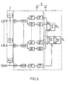
- This device 1 comprises a measuring cell 2, calculation means 4, excitation means 5 and display means 7.
- the measuring cell 2 is filled with a medium 3 adapted to propagate ultrasonic waves.
- the measuring cell comprises a tank 6 commonly called “water box” by the skilled person.
- a tube 8 In this tank 6 is immersed a tube 8.
- the tube 8 here constitutes the object that one seeks to characterize dimensionally.
- the tube 8 has internal and external outer and outer surfaces 12 substantially cylindrical about a longitudinal axis 14.
- Each probe Si is both a transmitter adapted to emit an ultrasonic pulse wave and a receiver adapted to detect ultrasonic waves propagated by the medium 3. These are for example piezoelectric elements.
- each of the probes Si is not critical. Indeed, on the one hand, the differences in distance with respect to the longitudinal axis 14 can be easily corrected using the calculation means 4 and, on the other hand, the angular position of each probe Si must simply be sufficient to allow an accuracy of 0.1% on the nominal thickness, which in practice allows without any problem a positioning error of the order of 1 degree.
- the measuring cell 2 also comprises a probe Sref for measuring the distance dref of a fixed reflector 18 to this probe Sref in order to allow the calculation means 4 to take into account the real speed of propagation of the ultrasound in the medium 3 to compensate the measurements di carried out by the probes Si.
- Displacement means (not shown), such as a conveyor, drive the tube 8 parallel to the longitudinal axis 14.
- the probes Si are connected on the one hand to the calculation means 4 and on the other hand to the excitation means 5.
- each probe Si generates a measurement signal, in response to the reception of an ultrasonic wave.
- Each measurement signal is processed by the calculation means 4.
- the calculation means 4 comprise first calculation means 22 and second calculation means 24.
- the analog amplifiers Ai and Aref are intended to condition the signals coming from the probes Si to bring them into the input dynamics of the CANi and CANref converters. For the reasons already set out above, the analog amplifiers Ai and Aref have a higher bandwidth than that of the Si probes.
- the CANi and CANref converters perform the sampling of the signals coming from the amplifiers Ai and Aref, with a temporal resolution compatible with the desired precision. Indeed, the precision on the measurement of time defines that of the characteristic curves which are the curves of thickness and diameter. In practice, sampling between 100 MHz and 200 MHz is sufficient. Indeed, subsequent digital processing can further increase this resolution if necessary.
- the intervals TOFdi, TOFepi and TOFref measure the ultrasound propagation times respectively on the distances di, epi and dref.
- the times corresponding to the distances di are measured between the emission pulse and the reflection echo on the outer surface 12 of the tube 8. They therefore correspond to the flight times of the ultrasonic waves on a path comprising a path between each probe If and the measuring point Pi, located on the outer surface 12 to the right of the probe Si, and a return between this measurement point Pi and the probe Si.
- the times corresponding to epi thicknesses are measured between the reflection echo on the outer wall 12 and the reflection echo on the inner wall 10. This corresponds to a synchronization on the input echo, that is to say say on the outer wall 12. This makes it possible to dispense with the relative position of the tube 8 with respect to the probe Si.
- the time corresponding to the distance dref is measured between the emission pulse and the reflection echo on the outer surface of the fixed reflector 18.
- the circuits TRTdi, TRTepi and TRTref receive the raw time measurements made by the circuits upstream, at the rate of the shots of the ultrasonic waves. This rate is for example 5 kHz.
- the TRTdi, TRTepi and TRTref circuits process the signals they receive, in real time, according to conventional filtering algorithms in the ultrasound domain, such as the rejection of aberrant measurements, the filtering of too fast variations between two consecutive measurements and sliding averaging to integrate measurements. These treatments are intended to eliminate erroneous measurements that do not correspond to a physical reality of the manufacturing process of the tube 8, so as to transmit to the second calculating means 24, downstream, error-free data.
- the second calculation means 24 comprise a CAL ⁇ diameter calculation circuit, and INTep and INT ⁇ interpolation circuits.
- the circuit CAL ⁇ calculates, from the measurements of distance di, the corresponding diameters of the tube 8. To do this, the measurements di are first corrected by a coefficient determined by the measurement dref, in order to compensate the variations of propagation velocity ultrasound in the medium 3.
- the interpolation circuits INTep and INT ⁇ interpolate the characteristic curves of thickness and diameter, so as to obtain a resolution of 96 points per revolution, ie an interpolation factor of 16.
- Interpolation circuits INTep, INT ⁇ can work in the spectral range, which makes it possible to directly obtain the eccentricity and ovalization values of the tube 8 from the six sampling points Pi sampled without having to calculate the interpolated curve.
- the period on which the totality of the variation of the distances di due to an eccentricity is observed corresponds to once the turn of the tube.
- the variations of distance observed for an ovality are observed twice when one carries out a turn of tube.
- this choice of six probes makes it possible to have a sufficient distance between each probe so that all the measurements are carried out simultaneously.
- the measurements can also be performed sequentially so as to reduce the cost of the equipment.
- it is sufficient to provide a simplified electronics which, instead of redundancy by six of the components of the calculation means 4 described above, can be reduced to a copy sequentially processing the signals collected on each of the probes Si. This nevertheless makes it possible to maintain a considerable increase in control speed since it is still a factor of 15 with six probes (two probes facing each other must necessarily carry out their measurements simultaneously for the calculation of the diameter).
- the interpolation factor is 16.
- Such an example of a curve is represented on the figure 4 .
- DSP circuits (acronym for the English expression “Digital Signal Processing") can be used for second calculation means 24 because they perform without problem this type of calculation in 200 microseconds.
- Interpolation can be done indifferently in the time domain by filtering or in the spectral domain by Fourier transform and inverse Fourier transform. One or the other of these methods is chosen according to the necessary interpolation factor.
- the number of coefficients for producing the low-pass filter necessary for filtering the interpolation operation in the time domain is important (for example, it is 128 for an interpolation factor of only 16). In this case, calculating the Fourier transform and then the inverse Fourier transform requires fewer resources than convolution processing in the time domain.
- the method also makes it possible to extract the ovalization of the internal diameter which is not possible directly to from the thickness curve because it returns the vector sum of internal and external ovalizations.
- This device applies primarily, but not exclusively, to dimensional ultrasonic testing of tubes and bars.
- the device also applies to the dimensional control of the tubes and bars by any other means of measurement than ultrasound, for example by optical means, by X-rays, etc.
- the device generally applies to the dimensional control of all products of continuous form without abrupt variation carried out by any means of dimensional measurement.
Landscapes
- Physics & Mathematics (AREA)
- General Physics & Mathematics (AREA)
- Acoustics & Sound (AREA)
- Health & Medical Sciences (AREA)
- Life Sciences & Earth Sciences (AREA)
- Chemical & Material Sciences (AREA)
- Analytical Chemistry (AREA)
- Biochemistry (AREA)
- General Health & Medical Sciences (AREA)
- Immunology (AREA)
- Pathology (AREA)
- Length Measuring Devices Characterised By Use Of Acoustic Means (AREA)
- Investigating Or Analyzing Materials By The Use Of Ultrasonic Waves (AREA)
- Heating, Cooling, Or Curing Plastics Or The Like In General (AREA)
- Manufacturing Of Printed Circuit Boards (AREA)
- Cylinder Crankcases Of Internal Combustion Engines (AREA)
- Bending Of Plates, Rods, And Pipes (AREA)
Claims (12)
- Vorrichtung zur Dimensionscharakterisierung eines Objekts (8) mit einer im Wesentlichen zylindrischen Oberfläche, die um eine Längsachse (14) rotationssymmetrisch ist, etwa eine Stange oder ein Rohr, die aufweist:- mindestens einen Sender (Si) zum Senden von mindestens zwei Impulswellen in ein Medium (3), das zum Ausbreiten jeder dieser Wellen jeweils zu einem unterschiedlichen Messpunkt (Pi) der zylindrischen Oberfläche geeignet ist,- mindestens einen Empfänger (Si) zum Empfangen der durch die zylindrische Oberfläche auf der Höhe von jedem der Messpunkte (Pi) reflektierten Impulswellen,- erste Mittel (22) zum Berechnen der Position von jedem der Messpunkte (Pi) anhand der Laufzeit der Impulswellen auf einer Strecke mit einem Lauf zwischen jedem Sender (Si) und dem entsprechenden Messpunkt (Pi) und einem Rücklauf zwischen diesem Messpunkt (Pi) und einem Empfänger (Si), und- zweite Mittel (24) zum Berechnen einer charakteristischen Kurve der zylindrischen Oberfläche auf 360 Grad um die Längsachse (14), die durch jeden der Messpunkte (Pi) verläuft, durch Interpolation anhand der entsprechenden Position von jedem dieser Punkte (Pi),dadurch gekennzeichnet, dass
die charakteristische Kurve Folgendem entspricht:a) entweder einer Kurve mit einer Dicke, die gegeben ist durch:
wobei- EpF die Amplitude der Veränderung der Dicke ist, die für eine Exzentrizität des Objekts in Bezug auf die Längsachse berechnet wird,- ϕF die Phase der Veränderung der Dicke ist, die für eine Exzentrizität des Objekts in Bezug auf die Längsachse berechnet wird,- Ep2F die Amplitude der Veränderung der Dicke ist, die für eine Unrundheit des Objekts berechnet wird,- ϕ2F die Phase der Veränderung der Dicke ist, die für eine Unrundheit des Objekts berechnet wird,- Epmoy der Mittelwert der Dicke ist, der über die Gesamtheit der Messpunkte berechnet wird,- t die Abtastperiode der interpolierten Kurve ist,b) oder dem Außendurchmesser, gegeben durch:
wobei- ∅Ext2F die Amplitude der Veränderung ist, die für den Außendurchmesser des Objekts berechnet wird,- ϕExt2F die Phase der Veränderung ist, die für den Außendurchmesser des Objekts berechnet wird,- ∅moy der Mittelwert des Durchmessers ist, der über die Gesamtheit der Messpunkte berechnet wird,- t die Abtastperiode der interpolierten Kurve ist,c) oder der Amplitude und der Phase der Unrundheit des Innendurchmessers, gegeben durch:wobei


 - Eplnti = epi -(∅i - ∅moy),- ∅moy: der Mittelwert des Durchmessers, der über die Gesamtheit der Messpunkte berechnet wird,- ∅i: ist ein Abtastwert des Außendurchmessers,- 2Fi ist die Unrundheitsfrequenz,- n ist gleich der Anzahl von Messpunkten.
 - Vorrichtung nach Anspruch 1, wobei jeder Sender (Si) und jeder Empfänger (Si) in Bezug auf das Objekt fest sind, das sich im Wesentlichen parallel zur Längsachse (14) verschiebt.
- Vorrichtung nach einem der vorangehenden Ansprüche, wobei jeder Sender (Si) auch ein Empfänger ist.
- Vorrichtung nach dem vorangehenden Anspruch mit mindestens vier Messpunkten (Pi), vorzugsweise sechs Messpunkten (Pi).
- Vorrichtung nach einem der vorangehenden Ansprüche mit mindestens vier Sendern (Si) und vier Empfängern, die um das Objekt (8) in im Wesentlichen symmetrischer Weise um die Längsachse (14) verteilt sind, um die Position von mindestens vier Messpunkten (Pi) zu bestimmen.
- Verfahren zur Dimensionscharakterisierung eines Objekts (8) mit einer im Wesentlichen zylindrischen Oberfläche, die um eine Längsachse (14) rotationssymmetrisch ist, etwa eine Stange oder ein Rohr, das aufweist:- Senden von mindestens zwei Impulswellen in ein Medium (3), das zum Ausbreiten jeder dieser Wellen jeweils zu einem unterschiedlichen Messpunkt (Pi) der zylindrischen Oberfläche geeignet ist,- Detektieren von durch die zylindrische Oberfläche auf der Höhe von jedem der Messpunkte (Pi) reflektierten Impulswellen,- Berechnen der Position von jedem der Messpunkte (Pi) anhand der Laufzeit der Impulswellen auf einer Strecke mit einem Lauf zwischen jedem Sender (Si) und dem entsprechenden Messpunkt (Pi) und einem Rücklauf zwischen diesem Messpunkt (Pi) und einem Empfänger (Si), und- Berechnen einer charakteristischen Kurve der zylindrischen Oberfläche auf 360 Grad um die Längsachse (14), die durch jeden der Messpunkte (Pi) verläuft, durch Interpolation anhand der entsprechenden Position von jedem dieser Punkte (Pi),dadurch gekennzeichnet, dass
die charakteristische Kurve Folgendem entspricht:a) entweder einer Kurve mit einer Dicke, die gegeben ist durch:
wobei- EpF die Amplitude der Veränderung der Dicke ist, die für eine Exzentrizität des Objekts in Bezug auf die Längsachse berechnet wird,- ϕF die Phase der Veränderung der Dicke ist, die für eine Exzentrizität des Objekts in Bezug auf die Längsachse berechnet wird,- Ep2F die Amplitude der Veränderung der Dicke ist, die für eine Unrundheit des Objekts berechnet wird,- ϕ2F die Phase der Veränderung der Dicke ist, die für eine Unrundheit des Objekts berechnet wird,- Epmoy der Mittelwert der Dicke ist, der über die Gesamtheit der Messpunkte berechnet wird,- t die Abtastperiode der interpolierten Kurve ist,b) oder dem Außendurchmesser, gegeben durch:
wobei- ∅Ext2F die Amplitude der Veränderung ist, die für den Außendurchmesser des Objekts berechnet wird,- ϕExt2F die Phase der Veränderung ist, die für den Außendurchmesser des Objekts berechnet wird,- ∅moy der Mittelwert des Durchmessers ist, der über die Gesamtheit der Messpunkte berechnet wird,- t die Abtastperiode der interpolierten Kurve ist,c) oder der Amplitude und der Phase der Unrundheit des Innendurchmessers, gegeben durch:wobei


 - Eplnti = epi - (∅i - ∅moy),- ∅moy: der Mittelwert des Durchmessers, der über die Gesamtheit der Messpunkte berechnet wird,- ∅i: ist ein Abtastwert des Außendurchmessers,- 2Fi ist die Unrundheitsfrequenz,- n ist gleich der Anzahl von Messpunkten.
 - Verfahren nach Anspruch 6, bei dem das Objekt (8) im Wesentlichen parallel zur Längsachse (14) verlagert wird.
- Verfahren nach einem der Ansprüche 6 und 7, bei dem die charakteristische Kurve anhand der Position von mindestens vier Messpunkten (Pi) berechnet wird.
- Verfahren nach einem der Ansprüche 6 bis 8, bei dem das Senden der Impulswellen ausgehend von einer Gesamtheit von Sendern, die im Wesentlichen gleich im Winkel um die Längsachse (14) verteilt sind, gleichzeitig stattfindet.
- Verfahren nach einem der Ansprüche 6 bis 8, bei dem das Senden der Impulswellen nacheinander an einer Gesamtheit von Sendern (Si) ausgeführt wird, die im Wesentlichen gleich im Winkel um die Längsachse (14) verteilt sind.
- Computerprogramm zur Ausführung, wenn dieses Programm auf einem Computer ausgeführt wird, eines Verfahrens zur Dimensionscharakterisierung eines Objekts (8) mit einer im Wesentlichen zylindrischen Oberfläche, die um eine Längsachse (14) rotationssymmetrisch ist, etwa eine Stange oder ein Rohr, wobei dieses Programm die Befehle aufweist, um- das Senden von mindestens zwei Impulswellen durch mindestens einen Sender (Si) auszulösen,- in synchronisierter Weise in Bezug auf das Senden der Impulswellen die Position von mindestens zwei Messpunkten (Pi) anhand von Daten zu berechnen, die durch mindestens einen Empfänger empfangen werden und einer durch die zylindrische Oberfläche reflektierten Impulswelle entsprechen, und- eine charakteristische Kurve der zylindrischen Oberfläche auf 360 Grad um die Längsachse (14), die durch jeden der Messpunkte (Pi) verläuft, durch Interpolation anhand der entsprechenden Position von jedem dieser Punkte (Pi) zu berechnen,dadurch gekennzeichnet, dass
die charakteristische Kurve Folgendem entspricht:a) entweder einer Kurve mit einer Dicke, die gegeben ist durch:
wobei- EpF die Amplitude der Veränderung der Dicke ist, die für eine Exzentrizität des Objekts in Bezug auf die Längsachse berechnet wird,- ϕF die Phase der Veränderung der Dicke ist, die für eine Exzentrizität des Objekts in Bezug auf die Längsachse berechnet wird,- Ep2F die Amplitude der Veränderung der Dicke ist, die für eine Unrundheit des Objekts berechnet wird,- ϕ2F die Phase der Veränderung der Dicke ist, die für eine Unrundheit des Objekts berechnet wird,- Epmoy der Mittelwert der Dicke ist, der über die Gesamtheit der Messpunkte berechnet wird,- t die Abtastperiode der interpolierten Kurve ist,b) oder dem Außendurchmesser, gegeben durch:
wobei- ∅Ext2F die Amplitude der Veränderung ist, die für den Außendurchmesser des Objekts berechnet wird,- ϕExt2F die Phase der Veränderung ist, die für den Außendurchmesser des Objekts berechnet wird,- ∅moy der Mittelwert des Durchmessers ist, der über die Gesamtheit der Messpunkte berechnet wird,- t die Abtastperiode der interpolierten Kurve ist,c) oder der Amplitude und der Phase der Unrundheit des Innendurchmessers, gegeben durch:wobei

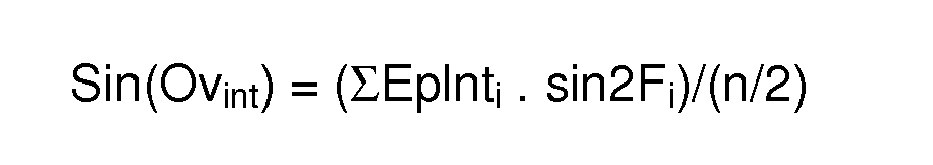
 - Eplnti = epi - (∅i - ∅moy),- ∅moy: der Mittelwert des Durchmessers, der über die Gesamtheit der Messpunkte berechnet wird,- ∅i: ist ein Abtastwert des Außendurchmessers,- 2Fi ist die Unrundheitsfrequenz,- n ist gleich der Anzahl von Messpunkten.
 - Programm nach Anspruch 11, wobei die charakteristische Kurve anhand der Position von mindestens vier Messpunkten (Pi) berechnet wird.
Applications Claiming Priority (2)
| Application Number | Priority Date | Filing Date | Title |
|---|---|---|---|
| FR0405694A FR2870936B1 (fr) | 2004-05-26 | 2004-05-26 | Dispositif et procede de caracterisation dimensionnelle d'un objet cylindrique |
| PCT/FR2005/001257 WO2006000668A1 (fr) | 2004-05-26 | 2005-05-19 | Dispositif et procédé de caractérisation dimensionnelle d'un objet cylindrique. |
Publications (2)
| Publication Number | Publication Date |
|---|---|
| EP1751494A1 EP1751494A1 (de) | 2007-02-14 |
| EP1751494B1 true EP1751494B1 (de) | 2010-03-17 |
Family
ID=34945930
Family Applications (1)
| Application Number | Title | Priority Date | Filing Date |
|---|---|---|---|
| EP05773262A Expired - Lifetime EP1751494B1 (de) | 2004-05-26 | 2005-05-19 | Vorrichtung und verfahren zur dimensionalen charakterisierung eines zylinderförmigen gegenstandes |
Country Status (7)
| Country | Link |
|---|---|
| US (1) | US8478563B2 (de) |
| EP (1) | EP1751494B1 (de) |
| JP (1) | JP4791455B2 (de) |
| AT (1) | ATE461420T1 (de) |
| DE (1) | DE602005019996D1 (de) |
| FR (1) | FR2870936B1 (de) |
| WO (1) | WO2006000668A1 (de) |
Families Citing this family (13)
| Publication number | Priority date | Publication date | Assignee | Title |
|---|---|---|---|---|
| EP1959229A1 (de) * | 2007-02-19 | 2008-08-20 | Nederlandse Organisatie Voor Toegepast-Natuurwetenschappelijk Onderzoek Tno | Ultraschall-Oberflächenüberwachung |
| KR101683518B1 (ko) * | 2015-07-22 | 2016-12-07 | 기아자동차 주식회사 | 비접촉 내구 진단 장치 및 방법 |
| US12358141B2 (en) | 2016-12-23 | 2025-07-15 | Gecko Robotics, Inc. | Systems, methods, and apparatus for providing interactive inspection map for inspection robot |
| US12162160B2 (en) | 2016-12-23 | 2024-12-10 | Gecko Robotics, Inc. | System, apparatus and method for improved location identification with prism |
| US11307063B2 (en) | 2016-12-23 | 2022-04-19 | Gtc Law Group Pc & Affiliates | Inspection robot for horizontal tube inspection having vertically positionable sensor carriage |
| US11673272B2 (en) | 2016-12-23 | 2023-06-13 | Gecko Robotics, Inc. | Inspection robot with stability assist device |
| CA3046651A1 (en) | 2016-12-23 | 2018-06-28 | Gecko Robotics, Inc. | Inspection robot |
| IT201800009209A1 (it) * | 2018-10-05 | 2020-04-05 | Sica Spa | Metodo e dispositivo di misurazione dell’ingombro della sezione trasversale di tubi |
| CA3173116A1 (en) | 2021-04-20 | 2022-10-20 | Edward A. Bryner | Flexible inspection robot |
| US11971389B2 (en) | 2021-04-22 | 2024-04-30 | Gecko Robotics, Inc. | Systems, methods, and apparatus for ultra-sonic inspection of a surface |
| US12566158B2 (en) | 2021-04-22 | 2026-03-03 | Gecko Robotics, Inc. | Robotic systems for ultrasonic surface inspection using shaped elements |
| CN114414028B (zh) * | 2022-01-25 | 2023-11-24 | 重庆医科大学 | 基于亚波长尺度的声波导管管内介质声速测量装置及方法 |
| WO2024097795A2 (en) | 2022-11-01 | 2024-05-10 | Gecko Robotics, Inc. | Inspection robot with profile adapting sled, couplant reduction film and transducer pod for thick assets |
Family Cites Families (16)
| Publication number | Priority date | Publication date | Assignee | Title |
|---|---|---|---|---|
| US3930404A (en) * | 1973-06-21 | 1976-01-06 | Exxon Nuclear Company Inc. | Inside diameter, outside diameter and wall tube gage |
| US4027527A (en) * | 1975-04-01 | 1977-06-07 | Aluminum Company Of America | System for determining tube eccentricity |
| BE840456A (fr) * | 1975-04-22 | 1976-10-07 | Dispositif de mesure precise des dimensions d'un objet par ultra-sons | |
| US4357672A (en) * | 1980-07-30 | 1982-11-02 | Science Accessories Corporation | Distance ranging apparatus and method |
| US4475399A (en) * | 1982-08-11 | 1984-10-09 | Livingston Waylon A | Apparatus for ultrasonic testing of tubular goods |
| JPS6293608A (ja) * | 1985-10-21 | 1987-04-30 | Kawasaki Steel Corp | ロ−ルプロフイ−ル測定方法および装置 |
| US4740146A (en) * | 1986-07-25 | 1988-04-26 | Peter Angelbeck | Apparatus for measuring and controlling the wall thickness of plastic pipes |
| JPS63263410A (ja) * | 1987-04-22 | 1988-10-31 | Komatsu Ltd | 円筒形状測定方法 |
| JPS6450903A (en) * | 1987-08-21 | 1989-02-27 | Nippon Kokan Kk | Measuring apparatus of shape of inside of tube |
| US5063780A (en) * | 1990-02-15 | 1991-11-12 | General Electric Company | Ultrasonic dimensional and flaw inspection of thin-walled tubular elements |
| US5156636A (en) * | 1990-11-26 | 1992-10-20 | Combustion Engineering, Inc. | Ultrasonic method and apparatus for measuring outside diameter and wall thickness of a tube and having temperature compensation |
| US5596508A (en) * | 1994-12-07 | 1997-01-21 | Krautkramer-Branson, Inc. | High resolution measurement of a thickness using ultrasound |
| JPH09184827A (ja) * | 1995-12-28 | 1997-07-15 | Mitsubishi Heavy Ind Ltd | 管内挿型超音波探触装置 |
| US6000288A (en) * | 1998-04-21 | 1999-12-14 | Southwest Research Institute | Determining average wall thickness and wall-thickness variation of a liquid-carrying pipe |
| US6634233B2 (en) | 2001-01-23 | 2003-10-21 | Wright State University | Method for determining the wall thickness and the speed of sound in a tube from reflected and transmitted ultrasound pulses |
| FR2833706B1 (fr) | 2001-12-13 | 2004-07-23 | Setval | Controle non destructif a capteurs ultrasonores, de produits de metallurgie |
-
2004
- 2004-05-26 FR FR0405694A patent/FR2870936B1/fr not_active Expired - Lifetime
-
2005
- 2005-05-19 US US11/569,524 patent/US8478563B2/en not_active Expired - Fee Related
- 2005-05-19 EP EP05773262A patent/EP1751494B1/de not_active Expired - Lifetime
- 2005-05-19 JP JP2007513997A patent/JP4791455B2/ja not_active Expired - Fee Related
- 2005-05-19 AT AT05773262T patent/ATE461420T1/de not_active IP Right Cessation
- 2005-05-19 DE DE602005019996T patent/DE602005019996D1/de not_active Expired - Lifetime
- 2005-05-19 WO PCT/FR2005/001257 patent/WO2006000668A1/fr not_active Ceased
Also Published As
| Publication number | Publication date |
|---|---|
| FR2870936A1 (fr) | 2005-12-02 |
| US20080059114A1 (en) | 2008-03-06 |
| ATE461420T1 (de) | 2010-04-15 |
| US8478563B2 (en) | 2013-07-02 |
| JP4791455B2 (ja) | 2011-10-12 |
| WO2006000668A1 (fr) | 2006-01-05 |
| JP2008500523A (ja) | 2008-01-10 |
| FR2870936B1 (fr) | 2006-09-01 |
| DE602005019996D1 (de) | 2010-04-29 |
| EP1751494A1 (de) | 2007-02-14 |
Similar Documents
| Publication | Publication Date | Title |
|---|---|---|
| EP1751494B1 (de) | Vorrichtung und verfahren zur dimensionalen charakterisierung eines zylinderförmigen gegenstandes | |
| EP0409054B1 (de) | Verfahren zur Verarbeitung eines elektrischen Distanzsignals | |
| EP1097354B1 (de) | Kreuzmessen von akustischen signalen eines durchflussmessers | |
| CA2968487C (fr) | Procede de detection et de caracterisation par ultrasons de defauts dans un materiau heterogene | |
| EP2780699B1 (de) | Verfahren zur rekonstruktion der geometrie einer oberfläche eines objekts durch echoloten, entsprechendes computerprogramm und vorrichtung zur ultraschallprüfung | |
| EP2834653B1 (de) | Verfahren und system zur diagnose eines kabels mittels verteilter reflektometrie mit selektiver durchschnittbildung | |
| FR2646513A1 (fr) | Procede et dispositif de diagraphie pour l'inspection acoustique d'un sondage muni d'un tubage | |
| EP0338618B1 (de) | Gerät zur Messung der Geschwindigkeit von Organen und der Blutströmung durch Korrelationsverfahren | |
| EP1113247A1 (de) | Verfahren und Vorrichtung zur Messung einer Flüssigkeitsströmung in einer Rohrleitung | |
| FR3113130A1 (fr) | Système de contrôle de la corrosion dans des structures métalliques par ondes guidées ultrasonores | |
| EP0161956A1 (de) | Verfahren zur eindeutigen Dopplergeschwindigkeitsmessung eines bewegten Objektes | |
| WO2012022886A1 (fr) | Procede de commande de transducteurs d'une sonde a ultrasons, programme d'ordinateur correspondant et dispositif de sondage a ultrasons | |
| EP0674185A1 (de) | Verfahren und Vorrichtung zum Detektieren und Charakterisieren eines Abschnitts eines Blutgefässes mit Ultraschall-Echographie | |
| FR2858062A1 (fr) | Appareil de mesure de temps de propagation acoustique | |
| EP3724652B1 (de) | Vorrichtung, system und verfahren zur bildgebung von defekten in einer struktur durch senden und empfangen von mechanischen wellen durch die struktur | |
| EP0197582B1 (de) | Verfahren und Vorrichtung zur Untersuchung von Medien mittels Ultraschall-Echographie | |
| CA2278408C (fr) | Procede et dispositif pour mesurer la vitesse d'ecoulement d'une veine fluide | |
| EP3612831B1 (de) | Messverfahren zur bestimmung mechanischer eigenschaften von anfangs flüssigen oder weichen medien und änderungen davon im laufe der zeit | |
| FR3050828B1 (fr) | Procede de determination d'une vitesse d'ecoulement d'un fluide s'ecoulant dans un troncon de conduite et dispositif associe | |
| EP4217727B1 (de) | Kalibrierungsverfahren für an zylinderartige strukturen angepasste geführte elastische wellentomografie | |
| WO2015193604A1 (fr) | Procede de controle non destructif et sans contact d'un objet ayant une surface complexe par sondage, programme d'ordinateur et dispositif de sondage correspondants | |
| EP4300095A1 (de) | Verfahren zur automatischen identifizierung einer akustischen quelle aus einem erzeugten akustischen signal | |
| EP3224571B1 (de) | Vorrichtung zur interferometrischen charakterisierung und entsprechendes verfahren | |
| WO2011055030A1 (fr) | Procede et appareil de caracterisation d'un ecoulement | |
| FR2855271A1 (fr) | Procede pour l'exploitation et l'analyse d'une structure volumique |
Legal Events
| Date | Code | Title | Description |
|---|---|---|---|
| PUAI | Public reference made under article 153(3) epc to a published international application that has entered the european phase |
Free format text: ORIGINAL CODE: 0009012 |
|
| 17P | Request for examination filed |
Effective date: 20061120 |
|
| AK | Designated contracting states |
Kind code of ref document: A1 Designated state(s): AT BE BG CH CY CZ DE DK EE ES FI FR GB GR HU IE IS IT LI LT LU MC NL PL PT RO SE SI SK TR |
|
| 17Q | First examination report despatched |
Effective date: 20070418 |
|
| DAX | Request for extension of the european patent (deleted) | ||
| GRAP | Despatch of communication of intention to grant a patent |
Free format text: ORIGINAL CODE: EPIDOSNIGR1 |
|
| GRAS | Grant fee paid |
Free format text: ORIGINAL CODE: EPIDOSNIGR3 |
|
| GRAA | (expected) grant |
Free format text: ORIGINAL CODE: 0009210 |
|
| AK | Designated contracting states |
Kind code of ref document: B1 Designated state(s): AT BE BG CH CY CZ DE DK EE ES FI FR GB GR HU IE IS IT LI LT LU MC NL PL PT RO SE SI SK TR |
|
| REG | Reference to a national code |
Ref country code: GB Ref legal event code: FG4D Free format text: NOT ENGLISH |
|
| REG | Reference to a national code |
Ref country code: CH Ref legal event code: EP |
|
| REG | Reference to a national code |
Ref country code: IE Ref legal event code: FG4D |
|
| REF | Corresponds to: |
Ref document number: 602005019996 Country of ref document: DE Date of ref document: 20100429 Kind code of ref document: P |
|
| REG | Reference to a national code |
Ref country code: SE Ref legal event code: TRGR |
|
| REG | Reference to a national code |
Ref country code: NL Ref legal event code: VDEP Effective date: 20100317 |
|
| PG25 | Lapsed in a contracting state [announced via postgrant information from national office to epo] |
Ref country code: LT Free format text: LAPSE BECAUSE OF FAILURE TO SUBMIT A TRANSLATION OF THE DESCRIPTION OR TO PAY THE FEE WITHIN THE PRESCRIBED TIME-LIMIT Effective date: 20100317 |
|
| LTIE | Lt: invalidation of european patent or patent extension |
Effective date: 20100317 |
|
| PG25 | Lapsed in a contracting state [announced via postgrant information from national office to epo] |
Ref country code: AT Free format text: LAPSE BECAUSE OF FAILURE TO SUBMIT A TRANSLATION OF THE DESCRIPTION OR TO PAY THE FEE WITHIN THE PRESCRIBED TIME-LIMIT Effective date: 20100317 Ref country code: FI Free format text: LAPSE BECAUSE OF FAILURE TO SUBMIT A TRANSLATION OF THE DESCRIPTION OR TO PAY THE FEE WITHIN THE PRESCRIBED TIME-LIMIT Effective date: 20100317 Ref country code: PL Free format text: LAPSE BECAUSE OF FAILURE TO SUBMIT A TRANSLATION OF THE DESCRIPTION OR TO PAY THE FEE WITHIN THE PRESCRIBED TIME-LIMIT Effective date: 20100317 Ref country code: SI Free format text: LAPSE BECAUSE OF FAILURE TO SUBMIT A TRANSLATION OF THE DESCRIPTION OR TO PAY THE FEE WITHIN THE PRESCRIBED TIME-LIMIT Effective date: 20100317 |
|
| REG | Reference to a national code |
Ref country code: IE Ref legal event code: FD4D |
|
| PG25 | Lapsed in a contracting state [announced via postgrant information from national office to epo] |
Ref country code: RO Free format text: LAPSE BECAUSE OF FAILURE TO SUBMIT A TRANSLATION OF THE DESCRIPTION OR TO PAY THE FEE WITHIN THE PRESCRIBED TIME-LIMIT Effective date: 20100317 Ref country code: CY Free format text: LAPSE BECAUSE OF FAILURE TO SUBMIT A TRANSLATION OF THE DESCRIPTION OR TO PAY THE FEE WITHIN THE PRESCRIBED TIME-LIMIT Effective date: 20100317 Ref country code: EE Free format text: LAPSE BECAUSE OF FAILURE TO SUBMIT A TRANSLATION OF THE DESCRIPTION OR TO PAY THE FEE WITHIN THE PRESCRIBED TIME-LIMIT Effective date: 20100317 Ref country code: ES Free format text: LAPSE BECAUSE OF FAILURE TO SUBMIT A TRANSLATION OF THE DESCRIPTION OR TO PAY THE FEE WITHIN THE PRESCRIBED TIME-LIMIT Effective date: 20100628 Ref country code: GR Free format text: LAPSE BECAUSE OF FAILURE TO SUBMIT A TRANSLATION OF THE DESCRIPTION OR TO PAY THE FEE WITHIN THE PRESCRIBED TIME-LIMIT Effective date: 20100618 Ref country code: NL Free format text: LAPSE BECAUSE OF FAILURE TO SUBMIT A TRANSLATION OF THE DESCRIPTION OR TO PAY THE FEE WITHIN THE PRESCRIBED TIME-LIMIT Effective date: 20100317 |
|
| BERE | Be: lapsed |
Owner name: SOCOMATE INTERNATIONAL Effective date: 20100531 |
|
| PG25 | Lapsed in a contracting state [announced via postgrant information from national office to epo] |
Ref country code: BG Free format text: LAPSE BECAUSE OF FAILURE TO SUBMIT A TRANSLATION OF THE DESCRIPTION OR TO PAY THE FEE WITHIN THE PRESCRIBED TIME-LIMIT Effective date: 20100617 Ref country code: CZ Free format text: LAPSE BECAUSE OF FAILURE TO SUBMIT A TRANSLATION OF THE DESCRIPTION OR TO PAY THE FEE WITHIN THE PRESCRIBED TIME-LIMIT Effective date: 20100317 Ref country code: IS Free format text: LAPSE BECAUSE OF FAILURE TO SUBMIT A TRANSLATION OF THE DESCRIPTION OR TO PAY THE FEE WITHIN THE PRESCRIBED TIME-LIMIT Effective date: 20100717 Ref country code: SK Free format text: LAPSE BECAUSE OF FAILURE TO SUBMIT A TRANSLATION OF THE DESCRIPTION OR TO PAY THE FEE WITHIN THE PRESCRIBED TIME-LIMIT Effective date: 20100317 |
|
| PG25 | Lapsed in a contracting state [announced via postgrant information from national office to epo] |
Ref country code: MC Free format text: LAPSE BECAUSE OF NON-PAYMENT OF DUE FEES Effective date: 20100531 |
|
| REG | Reference to a national code |
Ref country code: CH Ref legal event code: PL |
|
| PLBE | No opposition filed within time limit |
Free format text: ORIGINAL CODE: 0009261 |
|
| STAA | Information on the status of an ep patent application or granted ep patent |
Free format text: STATUS: NO OPPOSITION FILED WITHIN TIME LIMIT |
|
| PG25 | Lapsed in a contracting state [announced via postgrant information from national office to epo] |
Ref country code: DK Free format text: LAPSE BECAUSE OF FAILURE TO SUBMIT A TRANSLATION OF THE DESCRIPTION OR TO PAY THE FEE WITHIN THE PRESCRIBED TIME-LIMIT Effective date: 20100317 Ref country code: IE Free format text: LAPSE BECAUSE OF FAILURE TO SUBMIT A TRANSLATION OF THE DESCRIPTION OR TO PAY THE FEE WITHIN THE PRESCRIBED TIME-LIMIT Effective date: 20100317 Ref country code: PT Free format text: LAPSE BECAUSE OF FAILURE TO SUBMIT A TRANSLATION OF THE DESCRIPTION OR TO PAY THE FEE WITHIN THE PRESCRIBED TIME-LIMIT Effective date: 20100719 |
|
| 26N | No opposition filed |
Effective date: 20101220 |
|
| PG25 | Lapsed in a contracting state [announced via postgrant information from national office to epo] |
Ref country code: LI Free format text: LAPSE BECAUSE OF NON-PAYMENT OF DUE FEES Effective date: 20100531 Ref country code: CH Free format text: LAPSE BECAUSE OF NON-PAYMENT OF DUE FEES Effective date: 20100531 |
|
| PG25 | Lapsed in a contracting state [announced via postgrant information from national office to epo] |
Ref country code: BE Free format text: LAPSE BECAUSE OF NON-PAYMENT OF DUE FEES Effective date: 20100531 Ref country code: IT Free format text: LAPSE BECAUSE OF FAILURE TO SUBMIT A TRANSLATION OF THE DESCRIPTION OR TO PAY THE FEE WITHIN THE PRESCRIBED TIME-LIMIT Effective date: 20100317 |
|
| PG25 | Lapsed in a contracting state [announced via postgrant information from national office to epo] |
Ref country code: HU Free format text: LAPSE BECAUSE OF FAILURE TO SUBMIT A TRANSLATION OF THE DESCRIPTION OR TO PAY THE FEE WITHIN THE PRESCRIBED TIME-LIMIT Effective date: 20100918 Ref country code: LU Free format text: LAPSE BECAUSE OF NON-PAYMENT OF DUE FEES Effective date: 20100519 |
|
| PG25 | Lapsed in a contracting state [announced via postgrant information from national office to epo] |
Ref country code: TR Free format text: LAPSE BECAUSE OF FAILURE TO SUBMIT A TRANSLATION OF THE DESCRIPTION OR TO PAY THE FEE WITHIN THE PRESCRIBED TIME-LIMIT Effective date: 20100317 |
|
| REG | Reference to a national code |
Ref country code: FR Ref legal event code: PLFP Year of fee payment: 11 |
|
| REG | Reference to a national code |
Ref country code: FR Ref legal event code: PLFP Year of fee payment: 12 |
|
| REG | Reference to a national code |
Ref country code: FR Ref legal event code: PLFP Year of fee payment: 13 |
|
| PGFP | Annual fee paid to national office [announced via postgrant information from national office to epo] |
Ref country code: FR Payment date: 20170329 Year of fee payment: 13 |
|
| PGFP | Annual fee paid to national office [announced via postgrant information from national office to epo] |
Ref country code: GB Payment date: 20170517 Year of fee payment: 13 Ref country code: DE Payment date: 20170511 Year of fee payment: 13 |
|
| PGFP | Annual fee paid to national office [announced via postgrant information from national office to epo] |
Ref country code: SE Payment date: 20170515 Year of fee payment: 13 |
|
| REG | Reference to a national code |
Ref country code: DE Ref legal event code: R119 Ref document number: 602005019996 Country of ref document: DE |
|
| REG | Reference to a national code |
Ref country code: SE Ref legal event code: EUG |
|
| GBPC | Gb: european patent ceased through non-payment of renewal fee |
Effective date: 20180519 |
|
| PG25 | Lapsed in a contracting state [announced via postgrant information from national office to epo] |
Ref country code: SE Free format text: LAPSE BECAUSE OF NON-PAYMENT OF DUE FEES Effective date: 20180520 |
|
| PG25 | Lapsed in a contracting state [announced via postgrant information from national office to epo] |
Ref country code: FR Free format text: LAPSE BECAUSE OF NON-PAYMENT OF DUE FEES Effective date: 20180531 Ref country code: GB Free format text: LAPSE BECAUSE OF NON-PAYMENT OF DUE FEES Effective date: 20180519 Ref country code: DE Free format text: LAPSE BECAUSE OF NON-PAYMENT OF DUE FEES Effective date: 20181201 |