EP1752072A2 - Schaugestell-Befestigungssystem - Google Patents
Schaugestell-Befestigungssystem Download PDFInfo
- Publication number
- EP1752072A2 EP1752072A2 EP06254254A EP06254254A EP1752072A2 EP 1752072 A2 EP1752072 A2 EP 1752072A2 EP 06254254 A EP06254254 A EP 06254254A EP 06254254 A EP06254254 A EP 06254254A EP 1752072 A2 EP1752072 A2 EP 1752072A2
- Authority
- EP
- European Patent Office
- Prior art keywords
- panel
- panels
- profile
- cavity
- wall
- Prior art date
- Legal status (The legal status is an assumption and is not a legal conclusion. Google has not performed a legal analysis and makes no representation as to the accuracy of the status listed.)
- Granted
Links
- 238000004873 anchoring Methods 0.000 claims abstract description 15
- 230000008878 coupling Effects 0.000 claims description 16
- 238000010168 coupling process Methods 0.000 claims description 16
- 238000005859 coupling reaction Methods 0.000 claims description 16
- 239000004411 aluminium Substances 0.000 claims description 12
- 229910052782 aluminium Inorganic materials 0.000 claims description 12
- XAGFODPZIPBFFR-UHFFFAOYSA-N aluminium Chemical compound [Al] XAGFODPZIPBFFR-UHFFFAOYSA-N 0.000 claims description 12
- 230000000295 complement effect Effects 0.000 claims description 6
- 230000000694 effects Effects 0.000 claims description 3
- 229910052751 metal Inorganic materials 0.000 claims description 2
- 239000002184 metal Substances 0.000 claims description 2
- 238000009434 installation Methods 0.000 abstract description 10
- 230000008901 benefit Effects 0.000 description 9
- 239000000463 material Substances 0.000 description 6
- 238000004519 manufacturing process Methods 0.000 description 3
- 238000000034 method Methods 0.000 description 3
- 239000002023 wood Substances 0.000 description 3
- 238000010276 construction Methods 0.000 description 2
- 238000001125 extrusion Methods 0.000 description 2
- 238000003780 insertion Methods 0.000 description 2
- 230000037431 insertion Effects 0.000 description 2
- 230000003993 interaction Effects 0.000 description 2
- 229910000831 Steel Inorganic materials 0.000 description 1
- 230000015572 biosynthetic process Effects 0.000 description 1
- 238000000576 coating method Methods 0.000 description 1
- 239000002131 composite material Substances 0.000 description 1
- 230000014759 maintenance of location Effects 0.000 description 1
- 230000001737 promoting effect Effects 0.000 description 1
- 238000009877 rendering Methods 0.000 description 1
- 239000010959 steel Substances 0.000 description 1
- 239000000758 substrate Substances 0.000 description 1
Images




Classifications
-
- A—HUMAN NECESSITIES
- A47—FURNITURE; DOMESTIC ARTICLES OR APPLIANCES; COFFEE MILLS; SPICE MILLS; SUCTION CLEANERS IN GENERAL
- A47F—SPECIAL FURNITURE, FITTINGS, OR ACCESSORIES FOR SHOPS, STOREHOUSES, BARS, RESTAURANTS OR THE LIKE; PAYING COUNTERS
- A47F5/00—Show stands, hangers, or shelves characterised by their constructional features
- A47F5/08—Show stands, hangers, or shelves characterised by their constructional features secured to the wall, ceiling, or the like; Wall-bracket display devices
- A47F5/0807—Display panels, grids or rods used for suspending merchandise or cards supporting articles; Movable brackets therefor
- A47F5/0846—Display panels or rails with elongated channels; Sliders, brackets, shelves, or the like, slidably attached therein
Definitions
- the invention relates to commercial display mounting systems, of the kind typically fitted by a specialist shopfitter.
- it relates to an improved construction for a panel which forms part of a display wall, and which provides a mounting for a cantilevered display support.
- One requirement for commercial display systems is that they be versatile with respect to shelf or support positioning, in order to accommodate different types of displays and product lines.
- a commonly employed display system would be expected to include a plurality of cantilevered supports for shelving panels or the like, a display wall that features a plurality of display wall support mountings arranged in a suitable array, and a plurality of support brackets that can be inserted in selected ones of the mountings and which have a cantilevered arm that support the shelves or products at the display wall.
- the functional geometry of the interacting support mounting wall with respect to strength, ease of installation and removal, and cost, are strong marketplace differentiators between the available systems.
- a display mounting system of the above-described type, well known in the art in Australia is supplied by Australian Slatwall Industries Pty Ltd and is known as SLATWALL.
- Problems inherent with this type of system that will be familiar to those skilled in the art, include an inability to support heavy loads. These problems are described in more detail Australian Patent Document No. 2004201505 , the contents of which are incorporated herein by cross-reference.
- the above patent document further describes an improved shelving bracket mounting system and in particular describes an arcuate anchor portion for said cantilevered arms which has various benefits over the existing SLATWALL system, as well as a particular cavity profile for receiving said cantilevered arms which, in combination, provide a secure retention of the mount in the cavity having a very good strength and practical utility.
- the cavity profile described in the patent document provides a good level of support for the anchor portion which has a different profile to that of the cavity.
- a cavity which has an identical internal profile that is congruent or identical to the external profile of the anchor portion would provide improved support. That is, it would be most preferable to have a direct male-female correlation between the profiles of the anchor portion and cavity, i.e. a shape fit.
- a display wall for a product display system shelving brackets or similar items, said shelving brackets or similar items having a male anchor portion adapted to be received by an anchoring cavity, said wall said wall being comprised of:
- brackets for the support of shelves may be a major use for this invention, it may equally be applied to a variety of other related items such as hooks, coat rails or other specialised support or display items.
- An advantage of the system described above is essentially that the cavity for receiving the anchor portion of the cantilevered support is formed at the junction of the two panels. This means it is not necessary to cut or extrude what may be an otherwise difficult profile into the front of the panel itself. Instead, the desired profile is partly formed at the lower edge of the upper panel, partly at the upper edge of the lower panel, and the cavity itself is formed by the bringing together of these upper and lower edges in adjacent, spaced-apart arrangement, when installed.
- the ability to form the panel structure described above in a relatively rapid manner will allow the whole structure to be formed in a relatively rapid manner, saving in labour costs attendant on installing such a shelving system.
- a further advantage of such a system is that potentially only the relatively narrow opening of the cavity will be visible in the installed and assembled panel, promoting a better aesthetic in relation to the overall appearance of the panel.
- This design in particular facilitates the cost-effective mass production of standard said panels, in particular via aluminium extrusion.
- said anchoring cavity is adapted to receive an anchor portion having a profile which is an upwardly curved tab of substantially even thickness; in particular having a curved profile of a substantially constant radius of curvature, and advantageously wherein said curve extends though a substantially circular segment of approximately 90°, in order to fully exploit the advantages of the anchor portion identified in Australian Patent Document No 2004201505 , discussed above.
- the profile of said cavity is upwardly curved away from said anterior surface and is of substantially even height, in order to match the profile of the preferred anchor portion of the above described anchor portion.
- a particularly advantageous embodiment of the anchor portion and corresponding cavity is achieved where said curved profile is of a substantially constant radius of curvature. This allows considerable ease of installation and removal of said anchor portion.
- said curve extends though a substantially circular segment of approximately 90°.
- a particularly advantageous embodiment of the posterior projections of the upper and lower panels occurs wherein
- the display wall of any preceding claim wherein the coupling projection extending from the upper surface of said panel includes, in profile, a male tang, and wherein the coupling projection extending from the lower surface of said panel includes, in profile, a female cavity adapted to make resilient engagement with said tang.
- This arrangement has been found to be relatively simple to install, while providing the requisite strength for the support of the composite structure of which the panels form part.
- the coupling projection extending from the upper surface of said panel includes, in profile, one inner and one outer upwardly curved male tangs sharing substantially the same centre of curvature, and wherein the coupling projection extending from the lower surface of said panel includes, in profile, a female cavity adapted to receive said inner tang; and wherein said outer tang is adapted to make engagement with an outer surface of an identical said coupling projection extending from said lower surface.
- This embodiment provides great ease of installation and dismantling, as the structure allows a simple pivoting movement to engage the upper and lower panels and to manoeuvre them into position.
- said outer surface of said coupling projection extending from said lower surface features a convex curvature which substantially shares centre of curvature with said outer tang.
- the end of said outer tang features a detent notch adapted to make resilient engagement with a complementary detent depression in an upper portion of said coupling projection extending from said lower panel.
- the complementary notch and depression enhances the ability of the panels to make resilient engagement with one another.
- a modular display system including a plurality of panels, according to those defined above, and a plurality of removable cantilevered support brackets mountable to said wall at selectable anchoring locations, wherein the support brackets have a terminal male anchor portion adapted to be received in said anchoring cavity formed by the interlocking connection of said panels, according to those defined above.
- the posterior surface of said panels features two or more secondary posterior projections which are adapted to receive a positioning lug in the channel formed therebetween.
- One advantage of this system is that the panels may be installed very easily manually by simply positioning the channel formed by the secondary projections in front of the lug, and pushing the channel onto the lug.
- Another advantage is that the vertical positioning of the anchor-receiving channel is thereby made quite flexible, due to the fact that the lug anchor may be moved freely within the channel in the vertical support member, and thereby is enabled to engage with the panel at any height.
- the height at which the anchor receiving channel occurs is determined by the height and number of the panels which vertically support it from below.
- the lugs feature barb-like projections on their outer surface, said projections being arranged to engage with similar projections on the facing surfaces of said secondary posterior projections to effect said resilient connection, thereby forming a more secure installation of the panels.
- the lugs are made from steel.
- a preferred embodiment of the vertical support members is provided wherein said channel opening is, at predetermined positions, wider than the width of said lug anchors to allow said lug anchors to be inserted into said channel. This facilitates rapid installation of the overall system, in that the lug anchors may be inserted or removed.
- a mounting system for shelving brackets or similar items said shelving brackets or similar items having a male anchor portion adapted to be received by an anchoring cavity
- said system including at least one panel having an anterior face and a posterior face, said panel adapted to receive an anchor portion having a profile which is an upwardly curved tab of substantially even thickness via a cavity located in said anterior face, wherein said cavity is a horizontally oriented slot which has a profile substantially matching the profile of said anchor portion, featuring an upwardly curved portion of substantially even height, and wherein said slot is present in an insert which is received by said panel, said insert preferably being a length of extruded metal, such as aluminium.
- An advantage of such a system is that the matching of the profile of the cavity to the anchor portion is that the anchor portion may be supported along it's entire length, rather than at specific points, which increases the stability of the anchor portion.
- Another advantage is that the use of an insert to provide the required cavity allows the above advantageous cavity to be installed reliably in a variety of materials.
- FIG 1 there is shown a schematic profile of a junction of an upper panel 1 and a lower panel 2 according to the invention.
- the panels are shown to have anterior, or front, surfaces 3 and posterior or rear surfaces 4.
- the upper panel 1 features an upwardly curved portion 5 which is adapted to engage with the upper panel 1.
- This curved portion 5 features a male protrusion 6, further featuring an engaging notch 7.
- the upper surface 8 of this curved portion 5 features a curvature which is designed to directly engage with the underside surface of an anchor portion of a shelving bracket (not shown).
- the lower end of the upper panel 1 also features a rearwardly protruding member 9 which defines a female cavity 10 for receiving the upwardly curving portion 5 described above.
- the lower edge of the upper panel 1 also defines an upwardly curved surface 11, which is adapted to engage with an upper surface of an anchor portion of a shelving bracket (not shown).
- the upper edge (not shown) of the upper panel 1 features a profile identical to the upper edge of the lower panel 2.
- the lower edge (not shown) of the lower panel 2 features a profile identical to the lower edge of the upper panel 2.
- Both of the panels also feature two rearwardly protruding projections 13, which extend substantially across the width of the panels.
- a cavity (in the form of a channel) 14 is formed between said projections.
- the inner walls 15 of said channel 14 feature a barbed profile. This profile is adapted to receive an anchoring lug 16 for installation of the panels in a panelling system.
- FIG 2 there is shown the upper panel 1 and lower panel in interlocking engagement.
- FIG. 3 there is shown a junction between an upper panel 1 and a lower panel 2 of the type described above, thereby forming said cavity 12, and into which the anchor portion 20 of a shelving support bracket 21 (not shown in entirety) has been inserted.
- the shelving support bracket 21 is thereby effectively held in place on the "wall" formed by the interlocking panels by the interaction between the anchor portion 20 and the upper and lower panels, wherein the anchor portion 20 fits snugly inside said cavity 12 due to the curvature of the upper surface 8 of the curved portion 5 of the lower panel 2 and the curvature of the lower edge 11 of the upper panel 1 (which have been chosen to match the curvature of the anchor portion 20), and can only be removed by an upward pivoting of said bracket 21.
- the upper curved surface 22 of the anchor portion 20 interacts with the upper internal curved surface 11 of the cavity 12 in particular to prevent the anchor portion 20 being withdrawn in a horizontal direction from the cavity 20.
- the lower curved surface 23 of the anchor portion 20 rests on the lower curved surface of the cavity 8 to prevent downward movement of the shelving support bracket 21 and the back plate 24 of the shelving support bracket 20 presses on the front surface 3 of the lower panel 2 to prevent a downwards rotation in a clockwise direction (as shown) of the support bracket 21 relative to the anchor portion 20 as illustrated.
- FIG 4 shows an archetypal shelving support bracket 21 of the kind which may be used in conjunction with the present invention.
- the curved anchor portion 20 is illustrated attached to a horizontal plate 24.
- a cantilever member 25 adapted to support a shelf.
- Figures 5, 6, 7, 8 and 9 illustrate a number of examples of support brackets for various purposes, including hanging racks of different types and, particularly in Figure 8, a rack designed for holding compact disc cases.
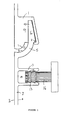
- the lug anchor consists of an aluminium block 32 into which the positioning lug 31 may be screwed or otherwise firmly affixed.
- the positioning lug 31 consists of a barrel portion 33, a barb portion 34 and a screwdriver-engaging portion 35. As illustrated, the barrel portion 33 connects that barb portion 34 to the lug anchor 30.
- the barb portion 34 consists of two conical protrusions 36 which are adapted to allow the easy insertion of the lug into the channel 14 formed by the posterior projections 13 to the panel 2 as described above.
- the positioning lugs are shaped to interact with the internal barbs 15 on the channel 14 as illustrated in Figure 1. This physical arrangement allows the panels to be securely fixed in position via interaction with the lugs.
- the screwdriver-engaging portion 35 in this particular embodiment illustrated as a Phillips-head screwdriver engaging portion, allows the lug 31 to be screwed directly into the block 30.
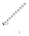
- FIG 11 there is a shown a vertical support member 40 for a shelving support system according to the invention.
- the support member as illustrated consists of an extruded aluminium beam 41, said beam featuring an overall "C-shape" profile.
- This profile provides an internal channel 42 of dimensions similar to the size of the block 32 which forms part of the lug anchor 30 as described above.
- This channel 42 is adapted thereby to receive the block 32 of the lug anchor 30 as illustrated.
- the gap in the channel has a width adapted to allow the barrel portion 31 of the positioning lug to protrude therethrough, in order to engage with the panels which comprise part of the system.
- the installer slides the lug anchor 32 down the channel 42 until it has reached the desired position where it will be required to attach to the panels. It will be noted that in this preferred embodiment the lug anchor 32 is sized so as to allow free movement of the lug anchor in the receiving channel 42. This allows considerable flexibility when installing panels of differing heights.
- At least one further opening 43 is provided to the channel 42 which is sized to allow the insertion of the entire lug anchor at an intermediate point along the channel 42, rather than exclusively at the end of the channel 42. This provides the installer with considerable flexibility, especially when working with longer versions of the support member 40, as regards the position in which the lug anchors 32 are inserted.
- FIG 12 there is shown a lug anchor 32 inserted in the channel 42 formed by the vertical support member 40, and wherein a positioning lug 31 is shown protruding through the gap in said channel 42.
- a positioning lug 31 is shown protruding through the gap in said channel 42.
- shown in dotted lines is the prospective position of a panel according to the invention.
- the positioning lug 31 has been inserted in between the rearward protrusions 13 to the panel 2, and has been received in a resilient manner inside the channel 14 formed between said protrusions. In this manner, the panels are attached to the support member during installation.
- FIG 13 there is shown a number of panels installed in an interlocking manner and connected to a vertical support member 40 in the manner described above.
- the panels are in fact slightly offset from their proper installed position, in order to illustrate the relative positioning of the panels and the positioning lugs 31.
- the 'wall' provided by the formation of the panels may be constructed of any number of separate interlocking panels.
- the panels may also be of varying heights, depending on the desired positioning of the shelf support inserts of the shelving system.
- all of components discussed above are constructed from extruded aluminium. This material is light and strong and the shapes of most of the components discussed above, in particular the panels and the vertical support member have been designed to facilitate their manufacture by this method. In particular, where the components are manufactured as aluminium extrusions, they may be produced relatively cheaply and can be delivered at precise dimensional tolerances. In addition, aluminium provides an ideal substrate for a variety of coatings and finishes.
- an extruded aluminium insert 50 is placed in an panel 51 made from another material, such as wood.
- the insert features a female cavity 52 which is adapted to receive the anchor portion of a shelving support bracket 53 (shown in dotted lines).
- the upper edge 70 of the relatively lower panel 71 features two upwardly curved portions (72,73) which are adapted to engage with the lower edge surface 74 of the relatively upper panel 75: an inner portion 73 and an outer portion 72 which define between them a channel 76 adapted to receive a complementary downwardly curved portion 77 of the lower surface 74 of the relatively upper panel 75 when said panels are in engagement.
- outer upwardly curved portion 72 features an engaging notch 78 which is adapted to engage the shoulder 79 of the rearwardly projecting part 80 of the lower edge 74 of the relatively upper panel 75 to effect locking into relative positions of the panels.
- Figure 18 shows a particularly advantageous version of the alternative embodiment depicted in Figures 15, 16 and 17, with respect to particular dimensions.
- FIG. 15, 16 and 17 has particular advantages, in that it is easier to install, by virtue of being able to insert the lower edge of an upper panel into the upper edge of an already installed lower panel by presenting the upper panel in a relatively perpendicular orientation, and causing the above described engagement structures to engage in the manner described by tilting the upper panel into an upright position parallel to the lower panel.
- This embodiment equally allows a far easier method of disassembly of the panelling structure by the reverse of the above described procedure.
Landscapes
- Display Racks (AREA)
- Connection Of Plates (AREA)
- Assembled Shelves (AREA)
- Devices For Indicating Variable Information By Combining Individual Elements (AREA)
Applications Claiming Priority (1)
| Application Number | Priority Date | Filing Date | Title |
|---|---|---|---|
| AU2005203620A AU2005203620B2 (en) | 2005-08-12 | 2005-08-12 | Display mounting system |
Publications (3)
| Publication Number | Publication Date |
|---|---|
| EP1752072A2 true EP1752072A2 (de) | 2007-02-14 |
| EP1752072A3 EP1752072A3 (de) | 2007-05-02 |
| EP1752072B1 EP1752072B1 (de) | 2015-05-20 |
Family
ID=37401526
Family Applications (1)
| Application Number | Title | Priority Date | Filing Date |
|---|---|---|---|
| EP20060254254 Not-in-force EP1752072B1 (de) | 2005-08-12 | 2006-08-14 | Schaugestell-Befestigungssystem |
Country Status (6)
| Country | Link |
|---|---|
| US (2) | US8056739B2 (de) |
| EP (1) | EP1752072B1 (de) |
| CN (1) | CN1911140B (de) |
| AU (1) | AU2005203620B2 (de) |
| CA (1) | CA2555729A1 (de) |
| NZ (2) | NZ554880A (de) |
Cited By (2)
| Publication number | Priority date | Publication date | Assignee | Title |
|---|---|---|---|---|
| WO2013029088A1 (en) * | 2011-08-26 | 2013-03-07 | John Hopkins | Improved display apparatus and method |
| WO2022229288A1 (en) * | 2021-04-27 | 2022-11-03 | Wilton Bradley Holdings Ltd | Play structure with activity board |
Families Citing this family (43)
| Publication number | Priority date | Publication date | Assignee | Title |
|---|---|---|---|---|
| AU2005203620B2 (en) * | 2005-08-12 | 2007-07-05 | John Hopkins | Display mounting system |
| US9138075B2 (en) | 2005-09-12 | 2015-09-22 | Rtc Industries, Inc. | Product management display system |
| US11344138B2 (en) | 2005-09-12 | 2022-05-31 | Rtc Industries, Inc. | Product management display system |
| US8978904B2 (en) | 2005-09-12 | 2015-03-17 | Rtc Industries, Inc. | Product management display system with trackless pusher mechanism |
| US10952546B2 (en) | 2005-09-12 | 2021-03-23 | Rtc Industries, Inc. | Product management display system with trackless pusher mechanism |
| US9173504B2 (en) | 2005-09-12 | 2015-11-03 | Rtc Industries, Inc. | Product management display system |
| US11259652B2 (en) | 2005-09-12 | 2022-03-01 | Rtc Industries, Inc. | Product management display system |
| US10285510B2 (en) | 2005-09-12 | 2019-05-14 | Rtc Industries, Inc. | Product management display system |
| US8739984B2 (en) | 2005-09-12 | 2014-06-03 | Rtc Industries, Inc. | Product management display system with trackless pusher mechanism |
| US11583109B2 (en) | 2005-09-12 | 2023-02-21 | Rtc Industries, Inc. | Product management display system with trackless pusher mechanism |
| WO2008088789A2 (en) * | 2007-01-16 | 2008-07-24 | Fasteners For Retail, Inc. | Merchandise security system |
| US8622227B2 (en) * | 2007-01-16 | 2014-01-07 | Fasteners For Retail, Inc. | Merchandise security system |
| US7717279B2 (en) * | 2007-08-08 | 2010-05-18 | Stephen Lawson | Slatwall track |
| USD611272S1 (en) | 2007-10-09 | 2010-03-09 | Master Lock Company Llc | Rail |
| MX2010003783A (es) * | 2007-10-09 | 2010-04-21 | Waterloo Ind Inc | Instalacion de montaje de almacenamiento para pared. |
| CN102984968A (zh) * | 2010-05-21 | 2013-03-20 | 沃特卢工业公司 | 墙壁存放安装系统 |
| CA2783173C (en) * | 2010-05-28 | 2016-07-12 | Jorge Pensi | Office workwall system |
| US8578662B1 (en) * | 2010-06-16 | 2013-11-12 | Raeanne Monk | Window well enclosure with attachable steps |
| US8826862B2 (en) * | 2011-09-18 | 2014-09-09 | Chih-Ching Lee | Support beam for pet furniture |
| AU339081S (en) * | 2011-09-22 | 2011-10-20 | Atkar Group Pty Ltd | Wall panel |
| US8800212B2 (en) | 2011-11-23 | 2014-08-12 | Parallax Group International, Llc | Wall mounting devices |
| DK2628412T3 (en) * | 2012-02-17 | 2015-04-27 | Vital Base As | Furniture element |
| KR101326041B1 (ko) * | 2012-08-20 | 2013-11-07 | (주)에이스 힌지텍 | 걸이용 패널 및 이를 이용한 걸이 장치 |
| ITMO20130121A1 (it) * | 2013-05-10 | 2014-11-11 | Fas S R L | Dispositivo per il supporto di mensole e simili |
| JP6785158B2 (ja) * | 2013-09-09 | 2020-11-18 | ロック アンド ロード シェルヴィング システムズ プロプライエタリー リミテッド | 調節可能な浮き棚システム |
| US10767685B2 (en) * | 2013-11-21 | 2020-09-08 | Medline Industries, Inc. | Hangable apparatus and systems and methods therefor |
| GB201401043D0 (en) * | 2014-01-21 | 2014-03-05 | Waterwall Ltd | Display apparatus |
| US9896213B2 (en) | 2014-03-27 | 2018-02-20 | C&D Zodiac, Inc. | Toilet module |
| EP3169195B1 (de) * | 2014-07-15 | 2018-09-26 | RTC Industries, Inc. | Produktverwaltungsanzeigesystem mit schienenmontageklammer |
| WO2016051613A1 (ja) * | 2014-10-02 | 2016-04-07 | 株式会社 ワン・バイ・ワン | 支持装置 |
| WO2016111628A1 (en) * | 2015-01-09 | 2016-07-14 | Opticon Sensors Europe B.V. | Modular wall system and panel element for use in such a system |
| CA2996029C (en) * | 2015-09-30 | 2019-06-04 | C&D Zodiac, Inc. | Toilet module |
| US10968090B2 (en) * | 2016-06-10 | 2021-04-06 | Altec Industries, Inc. | Modular rib for elevating platform |
| US10823327B2 (en) | 2016-06-10 | 2020-11-03 | Altec Industries, Inc. | Mounting system for elevating platform |
| US12187588B2 (en) | 2016-06-10 | 2025-01-07 | Altec Industries, Inc. | Modular rib |
| AU2019230455B2 (en) * | 2018-03-06 | 2024-02-01 | Clickstair Pty Ltd | Furniture system |
| US12232616B2 (en) * | 2018-11-16 | 2025-02-25 | The Parallax Group International, Llc | Wall and ceiling track system for mounting devices |
| US10799041B1 (en) * | 2019-03-26 | 2020-10-13 | Tag Hardware Systems Ltd. | Wall mounted organizer rack |
| CN110507120A (zh) * | 2019-08-21 | 2019-11-29 | 江阴嘉云铝材有限公司 | 一种展板系统及其快速安装方法 |
| US20220248873A1 (en) * | 2021-02-11 | 2022-08-11 | Boss Built Products Inc. | Organizer Wall Panel Assembly |
| USD1078108S1 (en) | 2022-02-15 | 2025-06-03 | 2840629 Ontario Inc. | Wall/ceiling panel |
| USD1080926S1 (en) | 2022-02-15 | 2025-06-24 | 2840629 Ontario Inc. | Wall/ceiling panel |
| USD1055321S1 (en) | 2022-02-16 | 2024-12-24 | 2840629 Ontario Inc. | Wall panel |
Citations (4)
| Publication number | Priority date | Publication date | Assignee | Title |
|---|---|---|---|---|
| GB2175626A (en) | 1985-04-12 | 1986-12-03 | Claus Ebert | A mounting plate for holding tools, containers, appliances or similar |
| EP0890331A1 (de) | 1997-07-11 | 1999-01-13 | Unifor S.p.A. | Einrichtung zum Verbinden von benachbarten Paneelen |
| EP1195117A2 (de) | 2000-10-09 | 2002-04-10 | Visplay IP AG | Einhängevorrichtung |
| AU2004201505A1 (en) | 2003-04-09 | 2004-10-28 | John Hopkins | Improved shelving bracket mounting system |
Family Cites Families (91)
| Publication number | Priority date | Publication date | Assignee | Title |
|---|---|---|---|---|
| US459844A (en) * | 1891-09-22 | Island | ||
| US576569A (en) * | 1897-02-09 | Board roofing and siding | ||
| US813816A (en) * | 1905-12-07 | 1906-02-27 | John C Mcvey | Fence-post. |
| US1281416A (en) * | 1917-02-10 | 1918-10-15 | Walter M Pratt | Insert for concrete construction. |
| US1921261A (en) * | 1931-07-13 | 1933-08-08 | Ainsworth Mfg Corp | Hinge construction |
| US3100556A (en) * | 1959-07-30 | 1963-08-13 | Reynolds Metals Co | Interlocking metallic structural members |
| US3085367A (en) * | 1959-11-27 | 1963-04-16 | Reynolds Metals Co | Interlocking extruded wall panelling |
| US3235218A (en) * | 1964-03-30 | 1966-02-15 | Harold E Graham | Article-display board |
| US3264792A (en) * | 1964-12-21 | 1966-08-09 | Zimmer Verfahrenstechnik | Suspension ceiling |
| US3352428A (en) * | 1965-10-23 | 1967-11-14 | Sak August | Adjustable mounting assembly |
| US3532317A (en) * | 1968-06-28 | 1970-10-06 | Tanger Ind | Suspensory element forming a support for demountable letters and the like |
| US3555762A (en) * | 1968-07-08 | 1971-01-19 | Aluminum Plastic Products Corp | False floor of interlocked metal sections |
| AT341738B (de) * | 1974-12-24 | 1978-02-27 | Hoesch Werke Ag | Verbundelement mit nut- und federverbindung |
| US4099358A (en) * | 1975-08-18 | 1978-07-11 | Intercontinental Truck Body - Montana, Inc. | Interlocking panel sections |
| US4008872A (en) * | 1975-10-08 | 1977-02-22 | Thompson Richard W | Module supporting system |
| FI55605C (fi) * | 1976-12-03 | 1979-09-10 | Juhani Suvitie | Saett foer installering av gardinbraede |
| DE2754814C2 (de) * | 1977-12-09 | 1986-10-09 | Hunter Douglas Industries B.V., Rotterdam | Wandelement mit einem Kern aus Dämmwerkstoffen |
| DE2828769A1 (de) * | 1978-06-30 | 1980-01-03 | Oltmanns Heinrich Fa | Kastenfoermige bautafel aus extrudiertem kunststoff |
| US4257492A (en) * | 1979-05-21 | 1981-03-24 | Rasada Jr Frank M | Bunk ladder anchor |
| US4420087A (en) * | 1980-03-12 | 1983-12-13 | Johns Robert L | Article display devices |
| US4323163A (en) * | 1980-03-12 | 1982-04-06 | Johns Robert L | Article display units and members for forming them |
| CA1177246A (en) * | 1981-09-11 | 1984-11-06 | Wilson (J.A.) Display Ltd. | Display panels |
| GB2117813A (en) * | 1982-04-06 | 1983-10-19 | Leonid Ostrovsky | Pivotal assembly of insulated wall panels |
| US4572381A (en) * | 1982-09-29 | 1986-02-25 | Breakey Fred B | Bracket board |
| US4531331A (en) * | 1983-05-27 | 1985-07-30 | Tamatoshi Industries Ltd. | Display apparatus |
| US4607753A (en) * | 1983-06-28 | 1986-08-26 | Ready Metal Manufacturing Company | Slotted wall merchandise display panel |
| US4632260A (en) * | 1984-05-04 | 1986-12-30 | John D. Krummell | Assemblable panel for a rack |
| US4591058A (en) * | 1984-05-10 | 1986-05-27 | Amstore Corporation | Slatboard |
| US4629076A (en) * | 1984-05-10 | 1986-12-16 | Amstore Corporation | Slatboard |
| US4817538A (en) * | 1984-05-30 | 1989-04-04 | Bang & Olufsen Of America, Inc. | Construction system for shelves |
| US4603068A (en) * | 1984-06-08 | 1986-07-29 | Harte Woodworking Limited | Display panel and a display panel system |
| US4615448A (en) * | 1985-09-27 | 1986-10-07 | Masonite Corporation | Display panel |
| US4891897A (en) * | 1985-12-12 | 1990-01-09 | Gieske Detlef J | Display panel |
| US4672789A (en) * | 1986-03-31 | 1987-06-16 | Guy Fortier | Surface covering extruded panel strip |
| US4674240A (en) * | 1986-05-01 | 1987-06-23 | American Desk Manufacturing Company | Wall panel system |
| US4750624A (en) * | 1986-07-18 | 1988-06-14 | Australian Slatwall Industries Pty. Ltd. | Extruded panel |
| US4805783A (en) * | 1986-07-23 | 1989-02-21 | Mayer John R | Slat wall advertising panel |
| US4852213A (en) * | 1987-10-13 | 1989-08-01 | Peter Shewchuk | Releasable extruded hinge |
| US4825601A (en) * | 1987-12-02 | 1989-05-02 | Halverson Lance K | Modular slotwall members |
| US4961295A (en) * | 1988-03-14 | 1990-10-09 | Kosch Sr Paul | Metal slat and wall system utilizing same |
| US4809479A (en) * | 1988-07-21 | 1989-03-07 | Tierno Michael A | Slat wall system |
| US5170605A (en) * | 1988-11-03 | 1992-12-15 | Trailmobile, Inc. | Refrigerator trailer floor construction |
| US4944416A (en) * | 1988-11-21 | 1990-07-31 | Petersen Robert J | Light-weight slot-wall display panel |
| US4936078A (en) * | 1988-12-02 | 1990-06-26 | Porter William H | Interconnecting panels |
| US4998304A (en) * | 1990-01-18 | 1991-03-12 | Sterling Plumbing Group, Inc. | Accessory mounting system for shower door frame |
| US5138803A (en) * | 1991-01-11 | 1992-08-18 | Commercial And Architectural Products, Inc. | Display panel assembly |
| US5185971A (en) * | 1991-05-17 | 1993-02-16 | Johnson Jr Hugh L | Channeled wall panel |
| US5125518A (en) * | 1991-08-12 | 1992-06-30 | Innovative Accessories | Interlocking hanging system |
| CA2074152C (en) * | 1992-07-17 | 1999-06-01 | Brian Wolcovitch | Display system |
| US5409120A (en) * | 1993-08-18 | 1995-04-25 | Hamilton Fixture Company | Slot wall display support system |
| US5412912A (en) * | 1994-03-15 | 1995-05-09 | Bo-Man, Inc. | Modular slatwall assembly |
| US5595038A (en) * | 1995-03-21 | 1997-01-21 | Prestenback; Alfred | Construction modules |
| US5647184A (en) * | 1996-01-22 | 1997-07-15 | L. B. Plastics Limited | Modular decking plank, and decking structure |
| US5819491A (en) * | 1996-01-22 | 1998-10-13 | L.B. Plastics Limited | Modular construction elements |
| WO1997030612A1 (en) * | 1996-02-23 | 1997-08-28 | Spectra Products Corporation | Free-standing modular slat-wall system |
| BE1010487A6 (nl) * | 1996-06-11 | 1998-10-06 | Unilin Beheer Bv | Vloerbekleding bestaande uit harde vloerpanelen en werkwijze voor het vervaardigen van dergelijke vloerpanelen. |
| US5819490A (en) * | 1996-10-04 | 1998-10-13 | International Visual Corporation | Slatwall section and method for making same |
| US5899344A (en) * | 1996-10-04 | 1999-05-04 | International Visual Corporation | Extruded slatwall section and method for making the same |
| US6131355A (en) * | 1996-11-21 | 2000-10-17 | Crane Plastics Company Limited Partnership | Deck plank |
| US5921044A (en) * | 1997-03-18 | 1999-07-13 | Holztrager; William J. | Display wall assembly and method of making same |
| US5791093A (en) * | 1997-03-19 | 1998-08-11 | Goer Manufacturing Company, Inc. | Slatwall panel and method of assembling same |
| US5857578A (en) * | 1997-05-09 | 1999-01-12 | Fishman; Eli | Slatwall display system and method therefor |
| USD404148S (en) * | 1997-07-25 | 1999-01-12 | Ready Metal Manufacturing Company | Slat wall panel |
| US5941026A (en) * | 1998-01-20 | 1999-08-24 | Storewall Llc | Slatwall display system |
| US6363645B1 (en) * | 1998-02-25 | 2002-04-02 | Bruce A Hunter | Insert for display panels |
| FR2785633B1 (fr) * | 1998-11-09 | 2001-02-09 | Valerie Roy | Panneau de recouvrement pour parquet, lambris ou analogue |
| US6349507B1 (en) * | 1999-03-15 | 2002-02-26 | Spectra Products Corporation | Slat wall structure with profile for different shelf support brackets and the like |
| US6325223B1 (en) * | 1999-03-26 | 2001-12-04 | Patwin Plastics, Inc. | Display wall section |
| US6311955B1 (en) * | 1999-04-26 | 2001-11-06 | Associated Materials, Incorporated | Fencing system with partial wrap components and tongue and groove board substitute |
| DE10044969B4 (de) * | 1999-09-10 | 2007-07-05 | Konrad Knoblauch Vermögensverwaltung GmbH | Wandprofilleiste |
| DE29922163U1 (de) * | 1999-12-17 | 2000-02-17 | Fehlbaum & Co., Muttenz | Anordnung zum Aufhängen von Artikeln oder zur Halterung einer Ablage |
| MXPA02009326A (es) * | 2000-03-24 | 2003-10-14 | Commercial And Architectural P | Sistema exhibidor de panel de mercancia. |
| BE1013569A3 (nl) * | 2000-06-20 | 2002-04-02 | Unilin Beheer Bv | Vloerbekleding. |
| US6421961B1 (en) * | 2000-07-11 | 2002-07-23 | Ernesto Mallozzi | Modular organizer |
| US6527565B1 (en) * | 2000-08-11 | 2003-03-04 | Robert L. Johns | Adjustable light display assembly |
| US6564952B1 (en) * | 2001-11-19 | 2003-05-20 | Royston, Llc | Merchandising display |
| US6772890B2 (en) * | 2002-04-03 | 2004-08-10 | Commercial And Architectural Products, Inc. | Narrow groove display panel |
| USD477423S1 (en) * | 2002-04-03 | 2003-07-15 | Commercial And Architectural Products, Inc. | Display panel |
| USD482552S1 (en) * | 2002-04-03 | 2003-11-25 | Commercial And Architectural Products, Inc. | Insert for a display panel |
| CA2380663C (en) * | 2002-04-04 | 2009-06-02 | Acclaim Design & Profiles Incorporated | Storage track |
| AUPS265502A0 (en) * | 2002-05-30 | 2002-06-20 | Ibj Resources Pty Ltd | Mounting system |
| EP1387016B1 (de) * | 2002-07-30 | 2006-12-27 | Hunter Douglas Industries B.V. | Paneelaufbau für abgehängte Decken |
| JP4184063B2 (ja) * | 2002-12-12 | 2008-11-19 | スガツネ工業株式会社 | 棚受け金具 |
| US7464511B2 (en) * | 2002-12-12 | 2008-12-16 | Paul James Kosch | Slat wall assembly |
| US7007433B2 (en) * | 2003-01-14 | 2006-03-07 | Centria | Features for thin composite architectural panels |
| JP3668479B2 (ja) * | 2003-01-31 | 2005-07-06 | 株式会社玉俊工業所 | 商品陳列装置 |
| USD482802S1 (en) * | 2003-02-28 | 2003-11-25 | Herbert Dale Yates, Jr. | Extruded slatwall section |
| US7694484B2 (en) * | 2003-10-31 | 2010-04-13 | James Walter Lucas | Panel edge joint |
| US20060012977A1 (en) * | 2004-07-02 | 2006-01-19 | Litesnow Llc | Slatwall lighting system |
| GB0426634D0 (en) * | 2004-12-03 | 2005-01-05 | Abbott Ooo | Display panel and display system |
| AU2005203620B2 (en) * | 2005-08-12 | 2007-07-05 | John Hopkins | Display mounting system |
-
2005
- 2005-08-12 AU AU2005203620A patent/AU2005203620B2/en not_active Ceased
- 2005-10-20 CN CN2005101093004A patent/CN1911140B/zh not_active Expired - Fee Related
-
2006
- 2006-08-09 CA CA002555729A patent/CA2555729A1/en not_active Abandoned
- 2006-08-09 NZ NZ554880A patent/NZ554880A/en not_active IP Right Cessation
- 2006-08-09 NZ NZ549123A patent/NZ549123A/en not_active IP Right Cessation
- 2006-08-11 US US11/503,374 patent/US8056739B2/en not_active Expired - Fee Related
- 2006-08-14 EP EP20060254254 patent/EP1752072B1/de not_active Not-in-force
-
2011
- 2011-09-27 US US13/246,777 patent/US8348070B2/en not_active Expired - Fee Related
Patent Citations (4)
| Publication number | Priority date | Publication date | Assignee | Title |
|---|---|---|---|---|
| GB2175626A (en) | 1985-04-12 | 1986-12-03 | Claus Ebert | A mounting plate for holding tools, containers, appliances or similar |
| EP0890331A1 (de) | 1997-07-11 | 1999-01-13 | Unifor S.p.A. | Einrichtung zum Verbinden von benachbarten Paneelen |
| EP1195117A2 (de) | 2000-10-09 | 2002-04-10 | Visplay IP AG | Einhängevorrichtung |
| AU2004201505A1 (en) | 2003-04-09 | 2004-10-28 | John Hopkins | Improved shelving bracket mounting system |
Cited By (2)
| Publication number | Priority date | Publication date | Assignee | Title |
|---|---|---|---|---|
| WO2013029088A1 (en) * | 2011-08-26 | 2013-03-07 | John Hopkins | Improved display apparatus and method |
| WO2022229288A1 (en) * | 2021-04-27 | 2022-11-03 | Wilton Bradley Holdings Ltd | Play structure with activity board |
Also Published As
| Publication number | Publication date |
|---|---|
| AU2005203620A1 (en) | 2007-03-01 |
| US20070079561A1 (en) | 2007-04-12 |
| NZ554880A (en) | 2008-08-29 |
| US8348070B2 (en) | 2013-01-08 |
| US20120012546A1 (en) | 2012-01-19 |
| CA2555729A1 (en) | 2007-02-12 |
| CN1911140A (zh) | 2007-02-14 |
| EP1752072A3 (de) | 2007-05-02 |
| AU2005203620B2 (en) | 2007-07-05 |
| EP1752072B1 (de) | 2015-05-20 |
| CN1911140B (zh) | 2011-02-16 |
| US8056739B2 (en) | 2011-11-15 |
| NZ549123A (en) | 2007-10-26 |
Similar Documents
| Publication | Publication Date | Title |
|---|---|---|
| EP1752072B1 (de) | Schaugestell-Befestigungssystem | |
| US6349507B1 (en) | Slat wall structure with profile for different shelf support brackets and the like | |
| US6325223B1 (en) | Display wall section | |
| EP1816931B1 (de) | Anzeigetafel und anzeigesystem | |
| US4809479A (en) | Slat wall system | |
| US8210368B2 (en) | Storage systems and methods of use of the same | |
| US8038112B2 (en) | Shelf support bracket and wall standard | |
| US7571571B1 (en) | Slatwall profile | |
| US20120199708A1 (en) | Wall mountable storage | |
| WO1994010404A1 (en) | Wall panel assembly | |
| US7261213B2 (en) | Closet partition system | |
| US6530485B1 (en) | Display units and bracket system | |
| WO2013166610A1 (en) | Bracket and wall standard assembly | |
| WO1991007121A1 (en) | Merchandise display unit | |
| US20060266901A1 (en) | Slotwall mounting bracket | |
| US4928913A (en) | Wall mounting system | |
| US11730287B1 (en) | Slatwall assembly and associated method of installing the same | |
| AU2008264216B2 (en) | Adjustable shelving | |
| GB2349803A (en) | Shelf structure | |
| EP1986522B1 (de) | Regalbodenkonsolen | |
| AU746815B2 (en) | Display panelling system | |
| JP3060729U (ja) | パネルシステム | |
| AU665108B2 (en) | Shelving support system | |
| CN115227050A (zh) | 抽屉 | |
| CA2174024A1 (en) | Adjustable standard system |
Legal Events
| Date | Code | Title | Description |
|---|---|---|---|
| PUAI | Public reference made under article 153(3) epc to a published international application that has entered the european phase |
Free format text: ORIGINAL CODE: 0009012 |
|
| 17P | Request for examination filed |
Effective date: 20060823 |
|
| AK | Designated contracting states |
Kind code of ref document: A2 Designated state(s): AT BE BG CH CY CZ DE DK EE ES FI FR GB GR HU IE IS IT LI LT LU LV MC NL PL PT RO SE SI SK TR |
|
| AX | Request for extension of the european patent |
Extension state: AL BA HR MK YU |
|
| PUAL | Search report despatched |
Free format text: ORIGINAL CODE: 0009013 |
|
| AK | Designated contracting states |
Kind code of ref document: A3 Designated state(s): AT BE BG CH CY CZ DE DK EE ES FI FR GB GR HU IE IS IT LI LT LU LV MC NL PL PT RO SE SI SK TR |
|
| AX | Request for extension of the european patent |
Extension state: AL BA HR MK YU |
|
| 17Q | First examination report despatched |
Effective date: 20071121 |
|
| AKX | Designation fees paid |
Designated state(s): AT BE BG CH CY CZ DE DK EE ES FI FR GB GR HU IE IS IT LI LT LU LV MC NL PL PT RO SE SI SK TR |
|
| GRAP | Despatch of communication of intention to grant a patent |
Free format text: ORIGINAL CODE: EPIDOSNIGR1 |
|
| INTG | Intention to grant announced |
Effective date: 20141219 |
|
| GRAS | Grant fee paid |
Free format text: ORIGINAL CODE: EPIDOSNIGR3 |
|
| GRAA | (expected) grant |
Free format text: ORIGINAL CODE: 0009210 |
|
| AK | Designated contracting states |
Kind code of ref document: B1 Designated state(s): AT BE BG CH CY CZ DE DK EE ES FI FR GB GR HU IE IS IT LI LT LU LV MC NL PL PT RO SE SI SK TR |
|
| REG | Reference to a national code |
Ref country code: GB Ref legal event code: FG4D |
|
| REG | Reference to a national code |
Ref country code: CH Ref legal event code: EP |
|
| REG | Reference to a national code |
Ref country code: AT Ref legal event code: REF Ref document number: 727277 Country of ref document: AT Kind code of ref document: T Effective date: 20150615 |
|
| REG | Reference to a national code |
Ref country code: IE Ref legal event code: FG4D |
|
| REG | Reference to a national code |
Ref country code: DE Ref legal event code: R096 Ref document number: 602006045459 Country of ref document: DE |
|
| REG | Reference to a national code |
Ref country code: AT Ref legal event code: MK05 Ref document number: 727277 Country of ref document: AT Kind code of ref document: T Effective date: 20150520 |
|
| REG | Reference to a national code |
Ref country code: LT Ref legal event code: MG4D |
|
| REG | Reference to a national code |
Ref country code: NL Ref legal event code: MP Effective date: 20150520 |
|
| PG25 | Lapsed in a contracting state [announced via postgrant information from national office to epo] |
Ref country code: PT Free format text: LAPSE BECAUSE OF FAILURE TO SUBMIT A TRANSLATION OF THE DESCRIPTION OR TO PAY THE FEE WITHIN THE PRESCRIBED TIME-LIMIT Effective date: 20150921 Ref country code: ES Free format text: LAPSE BECAUSE OF FAILURE TO SUBMIT A TRANSLATION OF THE DESCRIPTION OR TO PAY THE FEE WITHIN THE PRESCRIBED TIME-LIMIT Effective date: 20150520 Ref country code: LT Free format text: LAPSE BECAUSE OF FAILURE TO SUBMIT A TRANSLATION OF THE DESCRIPTION OR TO PAY THE FEE WITHIN THE PRESCRIBED TIME-LIMIT Effective date: 20150520 Ref country code: FI Free format text: LAPSE BECAUSE OF FAILURE TO SUBMIT A TRANSLATION OF THE DESCRIPTION OR TO PAY THE FEE WITHIN THE PRESCRIBED TIME-LIMIT Effective date: 20150520 |
|
| PGFP | Annual fee paid to national office [announced via postgrant information from national office to epo] |
Ref country code: DE Payment date: 20150821 Year of fee payment: 10 Ref country code: GB Payment date: 20150728 Year of fee payment: 10 |
|
| PG25 | Lapsed in a contracting state [announced via postgrant information from national office to epo] |
Ref country code: AT Free format text: LAPSE BECAUSE OF FAILURE TO SUBMIT A TRANSLATION OF THE DESCRIPTION OR TO PAY THE FEE WITHIN THE PRESCRIBED TIME-LIMIT Effective date: 20150520 Ref country code: GR Free format text: LAPSE BECAUSE OF FAILURE TO SUBMIT A TRANSLATION OF THE DESCRIPTION OR TO PAY THE FEE WITHIN THE PRESCRIBED TIME-LIMIT Effective date: 20150821 Ref country code: LV Free format text: LAPSE BECAUSE OF FAILURE TO SUBMIT A TRANSLATION OF THE DESCRIPTION OR TO PAY THE FEE WITHIN THE PRESCRIBED TIME-LIMIT Effective date: 20150520 Ref country code: IS Free format text: LAPSE BECAUSE OF FAILURE TO SUBMIT A TRANSLATION OF THE DESCRIPTION OR TO PAY THE FEE WITHIN THE PRESCRIBED TIME-LIMIT Effective date: 20150920 Ref country code: BG Free format text: LAPSE BECAUSE OF FAILURE TO SUBMIT A TRANSLATION OF THE DESCRIPTION OR TO PAY THE FEE WITHIN THE PRESCRIBED TIME-LIMIT Effective date: 20150820 |
|
| PG25 | Lapsed in a contracting state [announced via postgrant information from national office to epo] |
Ref country code: DK Free format text: LAPSE BECAUSE OF FAILURE TO SUBMIT A TRANSLATION OF THE DESCRIPTION OR TO PAY THE FEE WITHIN THE PRESCRIBED TIME-LIMIT Effective date: 20150520 Ref country code: EE Free format text: LAPSE BECAUSE OF FAILURE TO SUBMIT A TRANSLATION OF THE DESCRIPTION OR TO PAY THE FEE WITHIN THE PRESCRIBED TIME-LIMIT Effective date: 20150520 |
|
| REG | Reference to a national code |
Ref country code: DE Ref legal event code: R097 Ref document number: 602006045459 Country of ref document: DE |
|
| PG25 | Lapsed in a contracting state [announced via postgrant information from national office to epo] |
Ref country code: SK Free format text: LAPSE BECAUSE OF FAILURE TO SUBMIT A TRANSLATION OF THE DESCRIPTION OR TO PAY THE FEE WITHIN THE PRESCRIBED TIME-LIMIT Effective date: 20150520 Ref country code: CZ Free format text: LAPSE BECAUSE OF FAILURE TO SUBMIT A TRANSLATION OF THE DESCRIPTION OR TO PAY THE FEE WITHIN THE PRESCRIBED TIME-LIMIT Effective date: 20150520 Ref country code: PL Free format text: LAPSE BECAUSE OF FAILURE TO SUBMIT A TRANSLATION OF THE DESCRIPTION OR TO PAY THE FEE WITHIN THE PRESCRIBED TIME-LIMIT Effective date: 20150520 Ref country code: RO Free format text: LAPSE BECAUSE OF NON-PAYMENT OF DUE FEES Effective date: 20150520 |
|
| PLBE | No opposition filed within time limit |
Free format text: ORIGINAL CODE: 0009261 |
|
| STAA | Information on the status of an ep patent application or granted ep patent |
Free format text: STATUS: NO OPPOSITION FILED WITHIN TIME LIMIT |
|
| PG25 | Lapsed in a contracting state [announced via postgrant information from national office to epo] |
Ref country code: MC Free format text: LAPSE BECAUSE OF FAILURE TO SUBMIT A TRANSLATION OF THE DESCRIPTION OR TO PAY THE FEE WITHIN THE PRESCRIBED TIME-LIMIT Effective date: 20150520 Ref country code: LU Free format text: LAPSE BECAUSE OF FAILURE TO SUBMIT A TRANSLATION OF THE DESCRIPTION OR TO PAY THE FEE WITHIN THE PRESCRIBED TIME-LIMIT Effective date: 20150814 |
|
| REG | Reference to a national code |
Ref country code: CH Ref legal event code: PL |
|
| 26N | No opposition filed |
Effective date: 20160223 |
|
| PG25 | Lapsed in a contracting state [announced via postgrant information from national office to epo] |
Ref country code: LI Free format text: LAPSE BECAUSE OF NON-PAYMENT OF DUE FEES Effective date: 20150831 Ref country code: IT Free format text: LAPSE BECAUSE OF FAILURE TO SUBMIT A TRANSLATION OF THE DESCRIPTION OR TO PAY THE FEE WITHIN THE PRESCRIBED TIME-LIMIT Effective date: 20150520 Ref country code: CH Free format text: LAPSE BECAUSE OF NON-PAYMENT OF DUE FEES Effective date: 20150831 |
|
| PG25 | Lapsed in a contracting state [announced via postgrant information from national office to epo] |
Ref country code: SI Free format text: LAPSE BECAUSE OF FAILURE TO SUBMIT A TRANSLATION OF THE DESCRIPTION OR TO PAY THE FEE WITHIN THE PRESCRIBED TIME-LIMIT Effective date: 20150520 |
|
| REG | Reference to a national code |
Ref country code: IE Ref legal event code: MM4A |
|
| REG | Reference to a national code |
Ref country code: FR Ref legal event code: ST Effective date: 20160429 |
|
| PG25 | Lapsed in a contracting state [announced via postgrant information from national office to epo] |
Ref country code: IE Free format text: LAPSE BECAUSE OF NON-PAYMENT OF DUE FEES Effective date: 20150814 |
|
| PG25 | Lapsed in a contracting state [announced via postgrant information from national office to epo] |
Ref country code: FR Free format text: LAPSE BECAUSE OF NON-PAYMENT OF DUE FEES Effective date: 20150831 Ref country code: BE Free format text: LAPSE BECAUSE OF FAILURE TO SUBMIT A TRANSLATION OF THE DESCRIPTION OR TO PAY THE FEE WITHIN THE PRESCRIBED TIME-LIMIT Effective date: 20150520 |
|
| REG | Reference to a national code |
Ref country code: DE Ref legal event code: R119 Ref document number: 602006045459 Country of ref document: DE |
|
| GBPC | Gb: european patent ceased through non-payment of renewal fee |
Effective date: 20160814 |
|
| PG25 | Lapsed in a contracting state [announced via postgrant information from national office to epo] |
Ref country code: HU Free format text: LAPSE BECAUSE OF FAILURE TO SUBMIT A TRANSLATION OF THE DESCRIPTION OR TO PAY THE FEE WITHIN THE PRESCRIBED TIME-LIMIT; INVALID AB INITIO Effective date: 20060814 |
|
| PG25 | Lapsed in a contracting state [announced via postgrant information from national office to epo] |
Ref country code: SE Free format text: LAPSE BECAUSE OF FAILURE TO SUBMIT A TRANSLATION OF THE DESCRIPTION OR TO PAY THE FEE WITHIN THE PRESCRIBED TIME-LIMIT Effective date: 20150520 Ref country code: NL Free format text: LAPSE BECAUSE OF FAILURE TO SUBMIT A TRANSLATION OF THE DESCRIPTION OR TO PAY THE FEE WITHIN THE PRESCRIBED TIME-LIMIT Effective date: 20150520 Ref country code: CY Free format text: LAPSE BECAUSE OF FAILURE TO SUBMIT A TRANSLATION OF THE DESCRIPTION OR TO PAY THE FEE WITHIN THE PRESCRIBED TIME-LIMIT Effective date: 20150520 |
|
| PG25 | Lapsed in a contracting state [announced via postgrant information from national office to epo] |
Ref country code: DE Free format text: LAPSE BECAUSE OF NON-PAYMENT OF DUE FEES Effective date: 20170301 Ref country code: GB Free format text: LAPSE BECAUSE OF NON-PAYMENT OF DUE FEES Effective date: 20160814 |
|
| PG25 | Lapsed in a contracting state [announced via postgrant information from national office to epo] |
Ref country code: TR Free format text: LAPSE BECAUSE OF FAILURE TO SUBMIT A TRANSLATION OF THE DESCRIPTION OR TO PAY THE FEE WITHIN THE PRESCRIBED TIME-LIMIT Effective date: 20150520 |