EP1752253A1 - Spannvorrichtung sowie Verfahren zum Bearbeiten von an einer solchen Spannvorrichtung gespannten Werkstücken - Google Patents
Spannvorrichtung sowie Verfahren zum Bearbeiten von an einer solchen Spannvorrichtung gespannten Werkstücken Download PDFInfo
- Publication number
- EP1752253A1 EP1752253A1 EP06118799A EP06118799A EP1752253A1 EP 1752253 A1 EP1752253 A1 EP 1752253A1 EP 06118799 A EP06118799 A EP 06118799A EP 06118799 A EP06118799 A EP 06118799A EP 1752253 A1 EP1752253 A1 EP 1752253A1
- Authority
- EP
- European Patent Office
- Prior art keywords
- clamping
- clamping device
- workpiece
- clamped
- plane
- Prior art date
- Legal status (The legal status is an assumption and is not a legal conclusion. Google has not performed a legal analysis and makes no representation as to the accuracy of the status listed.)
- Granted
Links
- 238000000034 method Methods 0.000 title claims abstract description 5
- 238000003754 machining Methods 0.000 title abstract description 7
- 210000002445 nipple Anatomy 0.000 description 4
- 238000010276 construction Methods 0.000 description 1
Images

Classifications
-
- B—PERFORMING OPERATIONS; TRANSPORTING
- B23—MACHINE TOOLS; METAL-WORKING NOT OTHERWISE PROVIDED FOR
- B23Q—DETAILS, COMPONENTS, OR ACCESSORIES FOR MACHINE TOOLS, e.g. ARRANGEMENTS FOR COPYING OR CONTROLLING; MACHINE TOOLS IN GENERAL CHARACTERISED BY THE CONSTRUCTION OF PARTICULAR DETAILS OR COMPONENTS; COMBINATIONS OR ASSOCIATIONS OF METAL-WORKING MACHINES, NOT DIRECTED TO A PARTICULAR RESULT
- B23Q3/00—Devices holding, supporting, or positioning work or tools, of a kind normally removable from the machine
- B23Q3/02—Devices holding, supporting, or positioning work or tools, of a kind normally removable from the machine for mounting on a work-table, tool-slide, or analogous part
- B23Q3/06—Work-clamping means
-
- B—PERFORMING OPERATIONS; TRANSPORTING
- B23—MACHINE TOOLS; METAL-WORKING NOT OTHERWISE PROVIDED FOR
- B23Q—DETAILS, COMPONENTS, OR ACCESSORIES FOR MACHINE TOOLS, e.g. ARRANGEMENTS FOR COPYING OR CONTROLLING; MACHINE TOOLS IN GENERAL CHARACTERISED BY THE CONSTRUCTION OF PARTICULAR DETAILS OR COMPONENTS; COMBINATIONS OR ASSOCIATIONS OF METAL-WORKING MACHINES, NOT DIRECTED TO A PARTICULAR RESULT
- B23Q3/00—Devices holding, supporting, or positioning work or tools, of a kind normally removable from the machine
- B23Q3/02—Devices holding, supporting, or positioning work or tools, of a kind normally removable from the machine for mounting on a work-table, tool-slide, or analogous part
- B23Q3/10—Auxiliary devices, e.g. bolsters, extension members
- B23Q3/103—Constructional elements used for constructing work holders
Definitions
- the invention relates to a clamping device for clamping workpieces, pallets or devices with one or more first clamping means, which form a first clamping plane. Furthermore, the invention relates to a method for machining workpieces which are tensioned on such a clamping device.
- Such a clamping device is known for example as a machine table in common machine tools.
- the machine table can be equipped, for example, with quick-release cylinders as a clamping device on which the workpiece, the pallet or the device is clamped by means of retractable nipple positionally accurate.
- the workpiece to be machined is thereby clamped positionally accurate in the machine tool.
- the workpiece is positioned in a certain orientation within the machine tool, so that not all sides of the workpiece can be processed depending on the arrangement and design of the machine spindle.
- the invention is based on the problem, a clamping device of the type mentioned in such a way that a workpiece can be processed, for example, within a machine tool from a larger number of pages.
- the clamping device is characterized by second clamping means, which form a second clamping plane, which is arranged at an angle, preferably at right angles, to the first clamping plane.
- the workpiece is first clamped by means of the clamping means of a clamping plane, processed and then re-clamped for further processing in the other clamping plane.
- the workpiece, the pallet or the device can thus be clamped in at least two different orientations on the clamping device.
- the workpiece to be machined is also arranged in two different orientations to the machine spindle and can be machined at least from one additional side.
- a stiffening plate is clamped to the clamping means of the clamping plane to which no workpiece, pallet or device is currently stretched.
- the stiffening plate should be designed so that it corresponds in terms of their rigidity and / or their deformation behavior of the rigidity or the deformation behavior of the workpiece, the change palette or the device.
- tensioning devices deform elastically under the machining forces that occur in the machine tool. If now the workpiece to be machined is tensioned once in the first and then in the second clamping plane, this changes the rigidity of the overall structure of the clamping device and the elements clamped thereon and thus the deformation under the machining forces. This is at the expense of workpiece accuracy. Due to the stiffening plate, which is stretched at the respective straight free clamping plane, the rigidity and thus the deformation behavior of the overall structure remains the same. As a result, the machining accuracy is increased.
- the clamping device is provided with apertures, so that the workpiece to be machined as it also from its rear side, ie from the side facing the jig, can be edited. As a result, even a six-sided machining of the workpiece to be clamped is possible.
- the clamping device has a foot 10, by means of which the clamping device can be fastened, in particular screwed, on a machine table of a machine tool, for example.
- a foot 10 On the foot 10, two spaced apart upright columns 11, 12 are provided, each carrying at its end facing away from the foot 10 a balcony overhanging plateau 13, 14.
- Foot 10, columns 11, 12 and plateaus 13, 14 are integrally connected in the present case.
- the clamping device can also be designed as a welded construction or foot 10, columns 11, 12 and plateaus 13, 14 are bolted together or connected to each other in any other suitable manner. Looking at the tensioning device in a side view (seen in Fig. 1 from the left front), form the foot 10, the columns 11, 12 and the plateaus 13, 14 a forwardly open U. Between the columns 11, 12 and thus between the plateaus 13, 14 is a free space 15 is provided, the meaning will be described in more detail below.
- each two superimposed quick release cylinder 16 are provided, as for example, from DE 296 15 613 U1 are known.
- the quick-release cylinders 16 are arranged on the inside of the U formed by the clamping device of the columns 11, 12. They form with their bearing surfaces 17, a first clamping plane, wherein the bearing surfaces 17 in the present case, in fact, in a common plane, so aligned with each other, are arranged. This is not necessarily the case.
- the quick-release cylinders 16 and their support surfaces 17 are stepped to each other, so that a stepped "clamping plane" is formed.
- an exchange pallet 20 is tensioned, which has clamping devices on its upper side, in the present case swing clamps 21, for clamping a workpiece to be machined.
- the change palette 20 is stretched in a conventional manner by retractable nipples by means of the quick release cylinder 16 and 18 respectively.
- the change palette 20 is stretched to the columns 11, 12 by means of the quick release cylinder 16.
- the further quick release cylinder 18 clamp in a conventional manner by means of retractable nipple a stiffening plate 22.
- the stiffening plate 22 corresponds in terms of their rigidity and / or their deformation behavior of the removable pallet 20, so that the removable pallet 20 alternatively by means of the other quick-release cylinder 18 to the plateaus 13, 14th can be stretched and then the stiffening plate 22 by means of the first quick-release cylinder 16 to the columns 11, 12.
- the two clamping planes at right angles are arranged to each other.
- the tensioned on the removable pallet 20 workpiece can thus be stretched in two different orientations and edit with higher degree of freedom.
- two different clamping planes namely on the one hand by the quick release cylinder 16 and on the other hand by the quick release cylinder 18, are provided.
- more quick-release cylinder can be arranged so that more clamping levels arise.
- a flat (closed) removable pallet 20 is stretched on the jig.
- the exchange pallet 20 can also be formed with apertures analogous to the free space 15 or, as already indicated above, the workpiece can be clamped directly to the quick-release cylinders 16 or 18 by means of a retractable nipple fastened to it. In this case, it is then possible, the workpiece from the back, so by the Free space 15, to edit.
- Recesses 23 at the foot 10 and 24 at the back of the clamping device ensure unimpeded access through the machine spindle. However, since the cutouts 23 and 24 are at the expense of the rigidity of the clamping device, they may also be omitted or provided with stiffening ribs if necessary.
- the clamping planes can be formed instead of by the support surfaces 17, 19 of the quick release cylinder 16, 18 and by the change pallet 20 and stiffening plate 22 facing upper sides of the columns 11, 12 and the plateaus 13, 14.
- the quick release cylinders 16, 18 are inserted so that the bearing surfaces 17, 19 are lower by a certain value.
Landscapes
- Engineering & Computer Science (AREA)
- Mechanical Engineering (AREA)
- Jigs For Machine Tools (AREA)
- Turning (AREA)
- Electrical Discharge Machining, Electrochemical Machining, And Combined Machining (AREA)
- Grinding Of Cylindrical And Plane Surfaces (AREA)
Abstract
Description
- Die Erfindung betrifft eine Spannvorrichtung zum Spannen von Werkstücken, Wechselpaletten oder Vorrichtungen mit einem oder mehreren ersten Spannmitteln, welche eine erste Spannebene bilden. Ferner betrifft die Erfindung ein Verfahren zum Bearbeiten von Werkstücken, welche an einer solchen Spannvorrichtung gespannt sind.
- Eine solche Spannvorrichtung ist beispielsweise als Maschinentisch in gängigen Werkzeugmaschinen bekannt. Der Maschinentisch kann dabei zum Beispiel mit Schnellspannzylindern als Spannmittel bestückt sein, an denen das Werkstück, die Palette oder die Vorrichtung mittels Einzugsnippel positionsgenau gespannt wird. Das zu bearbeitende Werkstück ist hierdurch in der Werkzeugmaschine positionsgenau gespannt. Jedoch ist das Werkstück in einer bestimmten Orientierung innerhalb der Werkzeugmaschine positioniert, so daß je nach Anordnung und Ausführung der Maschinenspindel nicht alle Seiten des Werkstücks bearbeitet werden können.
- Hiervon ausgehend liegt der Erfindung das Problem zugrunde, eine Spannvorrichtung der eingangs genannten Art derart weiterzubilden, daß ein Werkstück beispielsweise innerhalb einer Werkzeugmaschine von einer größeren Anzahl von Seiten her bearbeitet werden kann.
- Zur Lösung dieses Problems ist die erfindungsgemäße Spannvorrichtung durch zweite Spannmittel gekennzeichnet, welche eine zweite Spannebene bilden, die unter einem Winkel, vorzugsweise rechtwinklig, zur ersten Spannebene angeordnet ist. Nach dem erfindungsgemäßen Verfahren wird das Werkstück zunächst mittels der Spannmittel der einen Spannebene gespannt, bearbeitet und dann zur weiteren Bearbeitung in die andere Spannebene umgespannt.
- Erfindungsgemäß läßt sich das Werkstück, die Palette oder die Vorrichtung also in wenigstens zwei verschiedenen Orientierungen an der Spannvorrichtung spannen. Dadurch ist das zu bearbeitende Werkstück auch in zwei unterschiedlichen Orientierungen zur Maschinenspindel angeordnet und kann wenigstens von einer zusätzlichen Seite bearbeitet werden.
- Vorzugsweise ist an den Spannmitteln der Spannebene, an der gerade kein Werkstück, Palette oder Vorrichtung gespannt ist, eine Versteifungsplatte gespannt. Die Versteifungsplatte sollte dabei so ausgelegt sein, daß sie hinsichtlich ihrer Steifigkeit und/oder ihres Verformungsverhaltens der Steifigkeit bzw. dem Verformungsverhalten des Werkstücks, der Wechsel palette oder der Vorrichtung entspricht. Spannvorrichtungen verformen sich nämlich elastisch unter den in der Werkzeugmaschine auftretenden Bearbeitungskräften. Wenn nun das zu bearbeitende Werkstück einmal in der ersten und dann in der zweiten Spannebene gespannt ist, verändert sich hierdurch die Steifigkeit des Gesamtgebildes aus Spannvorrichtung und den daran gespannten Elementen und damit die Verformung unter den Bearbeitungskräften. Dieses geht zu Lasten der Werkstückgenauigkeit. Aufgrund der Versteifungsplatte, die an der jeweils gerade freien Spannebene gespannt ist, bleibt die Steifigkeit und damit das Verformungsverhalten des Gesamtgebildes gleich. Hierdurch wird die Bearbeitungsgenauigkeit gesteigert.
- Nach einer auch unabhängig denkbaren Weiterbildung der Erfindung ist die Spannvorrichtung mit Durchbrüchen versehen, so daß das zu bearbeitende Werkstück gleichsam auch von seiner Rückseite, also von der der Spannvorrichtung zugewandten Seite her, bearbeitet werden kann. Hierdurch ist sogar eine Sechs-Seiten-Bearbeitung des zu spannenden Werkstücks möglich.
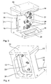
- Die Erfindung wird nachfolgend anhand eines in der Zeichnung dargestellten Ausführungsbeispiels näher erläutert. Es zeigen:
- Fig. 1
- eine Spannvorrichtung mit den Erfindungsmerkmalen in perspektivischer Darstellung,
- Fig. 2
- die Spannvorrichtung gemäß Fig. 1 mit Wechselpalette und Versteifungsplatte in perspektivischer Explosionsdarstellung,
- Fig. 3
- die Spannvorrichtung gemäß Fig. 1 mit angebrachter Wechsel palette und Versteifungsplatte in perspektivischer Darstellung,
- Fig. 4
- die Spannvorrichtung gemäß Fig. 3 mit Wechselpalette und Versteifungsplatte in einer anderen perspektivischen Ansicht.
- Die Spannvorrichtung weist einen Fuß 10 auf, mittels dessen die Spannvorrichtung beispielsweise auf einem Maschinentisch einer Werkzeugmaschine befestigbar, insbesondere verschraubbar, ist. Auf dem Fuß 10 sind zwei voneinander beabstandete aufrechte Säulen 11, 12 vorgesehen, welche jeweils an ihrem vom Fuß 10 abgewandten Ende ein balkonartig überhängendes Plateau 13, 14 tragen. Fuß 10, Säulen 11, 12 und Plateaus 13, 14 sind im vorliegenden Fall einstückig miteinander verbunden. Die Spannvorrichtung kann aber auch als Schweißkonstruktion ausgebildet sein oder Fuß 10, Säulen 11, 12 sowie Plateaus 13, 14 sind miteinander verschraubt oder auf andere geeignete Weise miteinander verbunden. Betrachtet man die Spannvorrichtung in einer Seitenansicht (in Fig. 1 von links vorne gesehen), bilden der Fuß 10, die Säulen 11, 12 sowie die Plateaus 13, 14 ein nach vorne offenes U. Zwischen den Säulen 11, 12 und damit auch zwischen den Plateaus 13, 14 ist ein Freiraum 15 vorgesehen, dessen Sinn weiter unten noch näher beschrieben wird.
- An den Säulen 11, 12 sind jeweils zwei übereinander angeordnete Schnellspannzylinder 16 vorgesehen, wie sie beispielsweise aus der
DE 296 15 613 U1 bekannt sind. Die Schnellspannzylinder 16 sind an der Innenseite des von der Spannvorrichtung gebildeten U der Säulen 11, 12 angeordnet. Sie bilden mit ihren Auflageflächen 17 eine erste Spannebene, wobei die Auflageflächen 17 im vorliegenden Fall tatsächlich in einer gemeinsamen Ebene, also zueinander fluchtend, angeordnet sind. Dieses ist aber nicht notwendigerweise der Fall. Bei bestimmten, abgestuften Werkstücken kann es durchaus auch sinnvoll sein, daß die Schnellspannzylinder 16 bzw. ihre Auflageflächen 17 zueinander abgestuft sind, so daß eine abgestufte "Spannebene" entsteht.
Auf den Plateaus 13, 14 sind an deren Oberseite, also an der von dem Fuß 10 abgewandten Seite, weitere Schnellspannzylinder 18 angeordnet, deren Zahl und Anordnung der Zahl und Anordnung der Schnellspannzylinder 16 an der Innenseite der Säulen 11, 12 entspricht. Die Auflageflächen 19 dieser weiteren Schnellspannzylinder 18 bilden wiederum eine gemeinsame, zweite Spannebene, wobei die Auflageflächen 18 wiederum zueinander fluchten, also in einer gemeinsamen Ebene angeordnet sind. Aber auch hier gilt, daß für entsprechend abgestufte Werkstücke auch die Auflageflächen 18 zueinander abgestuft angeordnet sein können, analog zu den Auflageflächen 17 der ersten Schnellspannzylinder 16. - Wie in Fig. 2 bis 4 gezeigt, wird mittels der Schnellspannzylinder 16 bzw. 18 eine Wechselpalette 20 gespannt, welche an ihrer Oberseite Spanneinrichtungen, im vorliegenden Fall Schwenkspanner 21, zum Spannen eines zu bearbeitenden Werkstücks aufweist. Die Wechsel palette 20 wird dabei in an sich bekannter Art durch Einzugsnippel mittels der Schnellspannzylinder 16 bzw. 18 gespannt. Im vorliegenden Fall ist die Wechsel palette 20 an den Säulen 11, 12 mittels der Schnellspannzylinder 16 gespannt. Die weiteren Schnellspannzylinder 18 spannen in an sich bekannter Art mittels Einzugsnippel eine Versteifungsplatte 22. Die Versteifungsplatte 22 entspricht hinsichtlich ihrer Steifigkeit und/oder ihres Verformungsverhaltens der Wechselpalette 20, so daß die Wechselpalette 20 alternativ auch mittels der weiteren Schnellspannzylinder 18 an den Plateaus 13, 14 gespannt werden kann und dann die Versteifungsplatte 22 mittels der ersten Schnellspannzylinder 16 an den Säulen 11, 12. Auf diese Weise entstehen für die Wechselpalette 20 zwei unterschiedliche, unter einem bestimmten Winkel zueinander stehende Spannebenen an der Spannvorrichtung, wobei im vorliegenden Fall die beiden Spannebenen rechtwinklig zueinander angeordnet sind. Das auf der Wechselpalette 20 gespannte Werkstück läßt sich somit in zwei unterschiedlichen Orientierungen spannen und mit höherem Freiheitsgrad bearbeiten.
- Im gezeigten Ausführungsbeispiel sind zwei unterschiedliche Spannebenen, nämlich einerseits durch die Schnellspannzylinder 16 und andererseits durch die Schnellspannzylinder 18, vorgesehen. Selbstverständlich können analog auch an den noch freien Seiten der Spannvorrichtung weitere Schnellspannzylinder angeordnet sein, so daß weitere Spannebenen entstehen.
- Bei dem gezeigten Ausführungsbeispiel ist eine ebene (geschlossene) Wechselpalette 20 an der Spannvorrichtung gespannt. Die Wechselpalette 20 kann aber auch mit Durchbrüchen analog zum Freiraum 15 ausgebildet sein oder, wie bereits weiter oben angedeutet, das Werkstück direkt mittels an ihm befestigter Einzugsnippel an den Schnellspannzylindern 16 bzw. 18 gespannt werden. In diesem Fall ist es dann möglich, das Werkstück auch von hinten, also durch den Freiraum 15, zu bearbeiten. Ausfräsungen 23 am Fuß 10 bzw. 24 an der Rückseite der Spannvorrichtung sorgen für einen ungehinderten Zugriff durch die Maschinenspindel. Da die Ausfräsungen 23 und 24 aber zu Lasten der Steifigkeit der Spannvorrichtung gehen, können sie erforderlichenfalls auch entfallen oder mit Versteifungsrippen versehen sein.
- Die Spannebenen können anstelle durch die Auflageflächen 17, 19 der Schnellspannzylinder 16, 18 auch durch die der Wechselpalette 20 bzw. Versteifungsplatte 22 zugewandten Oberseiten der Säulen 11, 12 bzw. der Plateaus 13, 14 gebildet werden. In diesem Fall sind die Schnellspannzylinder 16, 18 so eingelassen, daß die Auflageflächen 17, 19 um einen bestimmten Wert tiefer liegen.
-
- 10
- Fuß
- 11
- Säule
- 12
- Säule
- 13
- Plateau
- 14
- Plateau
- 15
- Freiraum
- 16
- Schnellspannzylinder
- 17
- Auflagefläche
- 18
- Schnellspannzylinder
- 19
- Auflagefläche
- 20
- Wechselpalette
- 21
- Schwenkspanner
- 22
- Versteifungsplatte
- 23
- Ausfräsung
- 24
- Ausfräsung
Claims (5)
- Spannvorrichtung zum Spannen von Werkstücken, Wechsel paletten (20) oder Vorrichtungen mit einem oder mehreren ersten Spannmitteln (16), welche eine erste Spannebene bilden, gekennzeichnet durch zweite Spannmittel (18), welche eine zweite Spannebene bilden, die unter einem Winkel, vorzugsweise rechtwinklig, zur ersten Spannebene angeordnet ist.
- Spannvorrichtung nach Anspruch 1, dadurch gekennzeichnet, daß an den Spannmitteln (16 bzw. 18) der Spannebene, an der gerade kein Werkstück, Palette (20) oder Vorrichtung gespannt ist, eine Versteifungsplatte (22) gespannt ist.
- Spannvorrichtung nach Anspruch 2, dadurch gekennzeichnet, daß die Versteifungsplatte (22) sich hinsichtlich ihrer Steifigkeit und/oder ihres Verformungsverhaltens der Steifigkeit bzw. dem Verformungsverhalten des Werkstücks, der Wechselpalette oder der Vorrichtung entspricht.
- Spannvorrichtung nach einem der Ansprüche 1 bis 3, gekennzeichnet durch Durchbrüche, durch welche das Werkstück zugänglich ist.
- Verfahren zum Bearbeiten von Werkstücken, welches an einer Spannvorrichtung nach einem der Ansprüche 1 bis 4 gespannt sind, in dem das Werkstück zunächst mittels der Spannmittel (16 bzw. 18) einer der Spannebenen gespannt, bearbeitet und dann zur weiteren Bearbeitung in die andere Spannebene umgespannt wird.
Applications Claiming Priority (1)
| Application Number | Priority Date | Filing Date | Title |
|---|---|---|---|
| DE102005038407A DE102005038407A1 (de) | 2005-08-12 | 2005-08-12 | Spannvorrichtung sowie Verfahren zum Bearbeiten von an einer solchen Spannvorrichtung gespannten Werkstücken |
Publications (2)
| Publication Number | Publication Date |
|---|---|
| EP1752253A1 true EP1752253A1 (de) | 2007-02-14 |
| EP1752253B1 EP1752253B1 (de) | 2010-08-04 |
Family
ID=37106253
Family Applications (1)
| Application Number | Title | Priority Date | Filing Date |
|---|---|---|---|
| EP06118799A Not-in-force EP1752253B1 (de) | 2005-08-12 | 2006-08-11 | Spannvorrichtung sowie Verfahren zum Bearbeiten von an einer solchen Spannvorrichtung gespannten Werkstücken |
Country Status (3)
| Country | Link |
|---|---|
| EP (1) | EP1752253B1 (de) |
| AT (1) | ATE476275T1 (de) |
| DE (2) | DE102005038407A1 (de) |
Cited By (5)
| Publication number | Priority date | Publication date | Assignee | Title |
|---|---|---|---|---|
| AT504994B1 (de) * | 2007-03-06 | 2009-07-15 | Armin Muser | Vorrichtung zum aufspannen von werkstücken auf einem bearbeitungszentrum |
| NL1036781C2 (nl) * | 2009-03-27 | 2010-09-28 | Auto Cell B V | Werkwijze voor het bewerken van een werkstuk alsmede een dergelijke bewerkingsinrichting. |
| ITMI20090849A1 (it) * | 2009-05-15 | 2010-11-16 | Balestrini Renzo Spa | Supporto a doppia funzione per il bloccaggio di pezzi in lavorazione |
| US8382081B2 (en) | 2010-09-21 | 2013-02-26 | Auto-Cell B.V. | Method for machining a workpiece as well as such machining device |
| DE102019133760A1 (de) * | 2019-12-10 | 2021-06-10 | Innoclamp GmbH | Modulares Spannsystem |
Families Citing this family (1)
| Publication number | Priority date | Publication date | Assignee | Title |
|---|---|---|---|---|
| DE202012102208U1 (de) * | 2012-06-15 | 2013-09-18 | Gressel Ag | Spannvorrichtung |
Citations (5)
| Publication number | Priority date | Publication date | Assignee | Title |
|---|---|---|---|---|
| US4968012A (en) * | 1989-05-10 | 1990-11-06 | Time Engineering, Inc. | Modular workpiece holding apparatus |
| WO1993024271A1 (fr) * | 1992-05-26 | 1993-12-09 | Aerospatiale | Outillage de prehension pour l'usinage de pieces sur une machine-outil |
| US5481811A (en) * | 1993-11-22 | 1996-01-09 | The Budd Company | Universal inspection workpiece holder |
| WO1997039655A1 (en) | 1996-04-19 | 1997-10-30 | Omni Structures International, Inc. | Modular tower tooling system |
| US5788225A (en) * | 1994-10-21 | 1998-08-04 | Kabushiki Kaisha Imao Corporation | Base and fixture to be used in machining operation |
-
2005
- 2005-08-12 DE DE102005038407A patent/DE102005038407A1/de not_active Withdrawn
-
2006
- 2006-08-11 AT AT06118799T patent/ATE476275T1/de active
- 2006-08-11 EP EP06118799A patent/EP1752253B1/de not_active Not-in-force
- 2006-08-11 DE DE502006007572T patent/DE502006007572D1/de active Active
Patent Citations (5)
| Publication number | Priority date | Publication date | Assignee | Title |
|---|---|---|---|---|
| US4968012A (en) * | 1989-05-10 | 1990-11-06 | Time Engineering, Inc. | Modular workpiece holding apparatus |
| WO1993024271A1 (fr) * | 1992-05-26 | 1993-12-09 | Aerospatiale | Outillage de prehension pour l'usinage de pieces sur une machine-outil |
| US5481811A (en) * | 1993-11-22 | 1996-01-09 | The Budd Company | Universal inspection workpiece holder |
| US5788225A (en) * | 1994-10-21 | 1998-08-04 | Kabushiki Kaisha Imao Corporation | Base and fixture to be used in machining operation |
| WO1997039655A1 (en) | 1996-04-19 | 1997-10-30 | Omni Structures International, Inc. | Modular tower tooling system |
Cited By (7)
| Publication number | Priority date | Publication date | Assignee | Title |
|---|---|---|---|---|
| AT504994B1 (de) * | 2007-03-06 | 2009-07-15 | Armin Muser | Vorrichtung zum aufspannen von werkstücken auf einem bearbeitungszentrum |
| NL1036781C2 (nl) * | 2009-03-27 | 2010-09-28 | Auto Cell B V | Werkwijze voor het bewerken van een werkstuk alsmede een dergelijke bewerkingsinrichting. |
| EP2233246A1 (de) * | 2009-03-27 | 2010-09-29 | Auto-Cell B.V. | Verfahren zur Bearbeitung eines Werkstücks und Bearbeitungsvorrichtung |
| ITMI20090849A1 (it) * | 2009-05-15 | 2010-11-16 | Balestrini Renzo Spa | Supporto a doppia funzione per il bloccaggio di pezzi in lavorazione |
| US8382081B2 (en) | 2010-09-21 | 2013-02-26 | Auto-Cell B.V. | Method for machining a workpiece as well as such machining device |
| DE102019133760A1 (de) * | 2019-12-10 | 2021-06-10 | Innoclamp GmbH | Modulares Spannsystem |
| DE102019133760B4 (de) | 2019-12-10 | 2023-05-04 | Innoclamp GmbH | Modulares Spannsystem und Verfahren |
Also Published As
| Publication number | Publication date |
|---|---|
| DE102005038407A1 (de) | 2007-02-15 |
| DE502006007572D1 (de) | 2010-09-16 |
| ATE476275T1 (de) | 2010-08-15 |
| EP1752253B1 (de) | 2010-08-04 |
Similar Documents
| Publication | Publication Date | Title |
|---|---|---|
| DE69532319T2 (de) | Träger und Spannvorrichtung für Bearbeitungsvorgänge | |
| EP1834724A1 (de) | Spanneinrichtung zum Festlegen von zu bearbeitenden Werkstücken an einer Werkzeugmaschine | |
| EP0254741B1 (de) | Vorrichtung zur halterung und handhabung eines flachen gegenstandes | |
| EP4221931B1 (de) | Winkelelement für ein schweiss- und spanntischsystem und baukastensystem zur herstellung verschiedener varianten eines winkelelements | |
| EP1741511A1 (de) | Spannvorrichtung für ein Werkzeug oder ein Werkstück | |
| EP1752253B1 (de) | Spannvorrichtung sowie Verfahren zum Bearbeiten von an einer solchen Spannvorrichtung gespannten Werkstücken | |
| DE2164093B2 (de) | Schneidwerkzeug | |
| DE2839320A1 (de) | Spannvorrichtung | |
| DE2840129A1 (de) | Befestigungsvorrichtung zum halten eines werkstuecks an einer werkzeugmaschine | |
| EP0873816A2 (de) | Positionier-Schnellspannzylinder | |
| DE3232496C2 (de) | Vorrichtung zur verschwenk- und feststellbaren Lagerung eines Maschinenschraubstockes auf einem Werkzeug-Maschinentisch | |
| DE3925642A1 (de) | Werkzeugmaschine | |
| DE10102488B4 (de) | Vorrichtung zur Höheneinstellung einer Mehrzahl von Werkzeughaltern für eine Abkantpresse | |
| DE202019003351U1 (de) | Schablone zur Herstellung von und Verwendung mit Locharbeitsplatten | |
| DE2705628C2 (de) | Aufbau-Werkzeugmaschine | |
| DE202009007827U1 (de) | Vakuumspannplatte | |
| DE19854214C1 (de) | Elementsystem | |
| DE2756627C3 (de) | Spannvorrichtung | |
| DE3105181A1 (de) | Schneidwerkzeug | |
| DE1402440A1 (de) | Auswechselbare Baukoerper zum Zusammenbau von Spannvorrichtungen fuer Werkzeugmaschinen | |
| DE202024102449U1 (de) | Vorrichtung zur Befestigung eines Schraubstocks an einem Tisch | |
| DE3102852C2 (de) | Hilfsvorrichtung zum Ausführen von Drechselarbeiten, insbesondere für Heimwerker | |
| AT395953B (de) | Spannvorrichtung fuer wendespanner von cnc-vertikalmaschinen | |
| DE102024114356A1 (de) | Vorrichtung zum Auflegen von Werkstücken und Schraubstock | |
| CH685808A5 (de) | Eckverleimpresse. |
Legal Events
| Date | Code | Title | Description |
|---|---|---|---|
| PUAI | Public reference made under article 153(3) epc to a published international application that has entered the european phase |
Free format text: ORIGINAL CODE: 0009012 |
|
| AK | Designated contracting states |
Kind code of ref document: A1 Designated state(s): AT BE BG CH CY CZ DE DK EE ES FI FR GB GR HU IE IS IT LI LT LU LV MC NL PL PT RO SE SI SK TR |
|
| AX | Request for extension of the european patent |
Extension state: AL BA HR MK YU |
|
| 17P | Request for examination filed |
Effective date: 20070814 |
|
| AKX | Designation fees paid |
Designated state(s): AT BE BG CH CY CZ DE DK EE ES FI FR GB GR HU IE IS IT LI LT LU LV MC NL PL PT RO SE SI SK TR |
|
| 17Q | First examination report despatched |
Effective date: 20071010 |
|
| GRAP | Despatch of communication of intention to grant a patent |
Free format text: ORIGINAL CODE: EPIDOSNIGR1 |
|
| GRAS | Grant fee paid |
Free format text: ORIGINAL CODE: EPIDOSNIGR3 |
|
| GRAA | (expected) grant |
Free format text: ORIGINAL CODE: 0009210 |
|
| AK | Designated contracting states |
Kind code of ref document: B1 Designated state(s): AT BE BG CH CY CZ DE DK EE ES FI FR GB GR HU IE IS IT LI LT LU LV MC NL PL PT RO SE SI SK TR |
|
| REG | Reference to a national code |
Ref country code: GB Ref legal event code: FG4D Free format text: NOT ENGLISH |
|
| REG | Reference to a national code |
Ref country code: CH Ref legal event code: EP |
|
| REG | Reference to a national code |
Ref country code: CH Ref legal event code: NV Representative=s name: BOVARD AG PATENTANWAELTE |
|
| REG | Reference to a national code |
Ref country code: IE Ref legal event code: FG4D Free format text: LANGUAGE OF EP DOCUMENT: GERMAN |
|
| REF | Corresponds to: |
Ref document number: 502006007572 Country of ref document: DE Date of ref document: 20100916 Kind code of ref document: P |
|
| REG | Reference to a national code |
Ref country code: NL Ref legal event code: VDEP Effective date: 20100804 |
|
| LTIE | Lt: invalidation of european patent or patent extension |
Effective date: 20100804 |
|
| PG25 | Lapsed in a contracting state [announced via postgrant information from national office to epo] |
Ref country code: FI Free format text: LAPSE BECAUSE OF FAILURE TO SUBMIT A TRANSLATION OF THE DESCRIPTION OR TO PAY THE FEE WITHIN THE PRESCRIBED TIME-LIMIT Effective date: 20100804 Ref country code: LT Free format text: LAPSE BECAUSE OF FAILURE TO SUBMIT A TRANSLATION OF THE DESCRIPTION OR TO PAY THE FEE WITHIN THE PRESCRIBED TIME-LIMIT Effective date: 20100804 Ref country code: NL Free format text: LAPSE BECAUSE OF FAILURE TO SUBMIT A TRANSLATION OF THE DESCRIPTION OR TO PAY THE FEE WITHIN THE PRESCRIBED TIME-LIMIT Effective date: 20100804 |
|
| BERE | Be: lapsed |
Owner name: LUDWIG EHRHARDT G.M.B.H. Effective date: 20100831 |
|
| PG25 | Lapsed in a contracting state [announced via postgrant information from national office to epo] |
Ref country code: PL Free format text: LAPSE BECAUSE OF FAILURE TO SUBMIT A TRANSLATION OF THE DESCRIPTION OR TO PAY THE FEE WITHIN THE PRESCRIBED TIME-LIMIT Effective date: 20100804 Ref country code: BG Free format text: LAPSE BECAUSE OF FAILURE TO SUBMIT A TRANSLATION OF THE DESCRIPTION OR TO PAY THE FEE WITHIN THE PRESCRIBED TIME-LIMIT Effective date: 20101104 Ref country code: IS Free format text: LAPSE BECAUSE OF FAILURE TO SUBMIT A TRANSLATION OF THE DESCRIPTION OR TO PAY THE FEE WITHIN THE PRESCRIBED TIME-LIMIT Effective date: 20101204 Ref country code: CY Free format text: LAPSE BECAUSE OF FAILURE TO SUBMIT A TRANSLATION OF THE DESCRIPTION OR TO PAY THE FEE WITHIN THE PRESCRIBED TIME-LIMIT Effective date: 20100804 Ref country code: SI Free format text: LAPSE BECAUSE OF FAILURE TO SUBMIT A TRANSLATION OF THE DESCRIPTION OR TO PAY THE FEE WITHIN THE PRESCRIBED TIME-LIMIT Effective date: 20100804 Ref country code: PT Free format text: LAPSE BECAUSE OF FAILURE TO SUBMIT A TRANSLATION OF THE DESCRIPTION OR TO PAY THE FEE WITHIN THE PRESCRIBED TIME-LIMIT Effective date: 20101206 |
|
| REG | Reference to a national code |
Ref country code: IE Ref legal event code: FD4D |
|
| PG25 | Lapsed in a contracting state [announced via postgrant information from national office to epo] |
Ref country code: GR Free format text: LAPSE BECAUSE OF FAILURE TO SUBMIT A TRANSLATION OF THE DESCRIPTION OR TO PAY THE FEE WITHIN THE PRESCRIBED TIME-LIMIT Effective date: 20101105 Ref country code: LV Free format text: LAPSE BECAUSE OF FAILURE TO SUBMIT A TRANSLATION OF THE DESCRIPTION OR TO PAY THE FEE WITHIN THE PRESCRIBED TIME-LIMIT Effective date: 20100804 Ref country code: MC Free format text: LAPSE BECAUSE OF NON-PAYMENT OF DUE FEES Effective date: 20100831 Ref country code: SE Free format text: LAPSE BECAUSE OF FAILURE TO SUBMIT A TRANSLATION OF THE DESCRIPTION OR TO PAY THE FEE WITHIN THE PRESCRIBED TIME-LIMIT Effective date: 20100804 |
|
| REG | Reference to a national code |
Ref country code: CH Ref legal event code: PFA Owner name: LUDWIG EHRHARDT GMBH Free format text: LUDWIG EHRHARDT GMBH#ROEMHELDSTRASSE 1-5#35321 LAUBACH (DE) -TRANSFER TO- LUDWIG EHRHARDT GMBH#ROEMHELDSTRASSE 1-5#35321 LAUBACH (DE) |
|
| PG25 | Lapsed in a contracting state [announced via postgrant information from national office to epo] |
Ref country code: DK Free format text: LAPSE BECAUSE OF FAILURE TO SUBMIT A TRANSLATION OF THE DESCRIPTION OR TO PAY THE FEE WITHIN THE PRESCRIBED TIME-LIMIT Effective date: 20100804 Ref country code: IE Free format text: LAPSE BECAUSE OF FAILURE TO SUBMIT A TRANSLATION OF THE DESCRIPTION OR TO PAY THE FEE WITHIN THE PRESCRIBED TIME-LIMIT Effective date: 20100804 |
|
| PG25 | Lapsed in a contracting state [announced via postgrant information from national office to epo] |
Ref country code: EE Free format text: LAPSE BECAUSE OF FAILURE TO SUBMIT A TRANSLATION OF THE DESCRIPTION OR TO PAY THE FEE WITHIN THE PRESCRIBED TIME-LIMIT Effective date: 20100804 Ref country code: IT Free format text: LAPSE BECAUSE OF FAILURE TO SUBMIT A TRANSLATION OF THE DESCRIPTION OR TO PAY THE FEE WITHIN THE PRESCRIBED TIME-LIMIT Effective date: 20100804 Ref country code: CZ Free format text: LAPSE BECAUSE OF FAILURE TO SUBMIT A TRANSLATION OF THE DESCRIPTION OR TO PAY THE FEE WITHIN THE PRESCRIBED TIME-LIMIT Effective date: 20100804 Ref country code: SK Free format text: LAPSE BECAUSE OF FAILURE TO SUBMIT A TRANSLATION OF THE DESCRIPTION OR TO PAY THE FEE WITHIN THE PRESCRIBED TIME-LIMIT Effective date: 20100804 Ref country code: RO Free format text: LAPSE BECAUSE OF FAILURE TO SUBMIT A TRANSLATION OF THE DESCRIPTION OR TO PAY THE FEE WITHIN THE PRESCRIBED TIME-LIMIT Effective date: 20100804 |
|
| PLBE | No opposition filed within time limit |
Free format text: ORIGINAL CODE: 0009261 |
|
| STAA | Information on the status of an ep patent application or granted ep patent |
Free format text: STATUS: NO OPPOSITION FILED WITHIN TIME LIMIT |
|
| PG25 | Lapsed in a contracting state [announced via postgrant information from national office to epo] |
Ref country code: ES Free format text: LAPSE BECAUSE OF FAILURE TO SUBMIT A TRANSLATION OF THE DESCRIPTION OR TO PAY THE FEE WITHIN THE PRESCRIBED TIME-LIMIT Effective date: 20101115 |
|
| 26N | No opposition filed |
Effective date: 20110506 |
|
| GBPC | Gb: european patent ceased through non-payment of renewal fee |
Effective date: 20101104 |
|
| PG25 | Lapsed in a contracting state [announced via postgrant information from national office to epo] |
Ref country code: BE Free format text: LAPSE BECAUSE OF NON-PAYMENT OF DUE FEES Effective date: 20100831 |
|
| REG | Reference to a national code |
Ref country code: DE Ref legal event code: R097 Ref document number: 502006007572 Country of ref document: DE Effective date: 20110506 |
|
| REG | Reference to a national code |
Ref country code: DE Ref legal event code: R082 Ref document number: 502006007572 Country of ref document: DE Representative=s name: ZACCO DR. PETERS UND PARTNER, DE Ref country code: DE Ref legal event code: R082 Ref document number: 502006007572 Country of ref document: DE Representative=s name: ZACCO PATENT- UND RECHTSANWALTS GMBH, DE Ref country code: DE Ref legal event code: R082 Ref document number: 502006007572 Country of ref document: DE Representative=s name: ZACCO PATENTANWALTS- UND RECHTSANWALTSGESELLSC, DE |
|
| PG25 | Lapsed in a contracting state [announced via postgrant information from national office to epo] |
Ref country code: GB Free format text: LAPSE BECAUSE OF NON-PAYMENT OF DUE FEES Effective date: 20101104 |
|
| PG25 | Lapsed in a contracting state [announced via postgrant information from national office to epo] |
Ref country code: HU Free format text: LAPSE BECAUSE OF FAILURE TO SUBMIT A TRANSLATION OF THE DESCRIPTION OR TO PAY THE FEE WITHIN THE PRESCRIBED TIME-LIMIT Effective date: 20110205 Ref country code: LU Free format text: LAPSE BECAUSE OF NON-PAYMENT OF DUE FEES Effective date: 20100811 |
|
| PG25 | Lapsed in a contracting state [announced via postgrant information from national office to epo] |
Ref country code: TR Free format text: LAPSE BECAUSE OF FAILURE TO SUBMIT A TRANSLATION OF THE DESCRIPTION OR TO PAY THE FEE WITHIN THE PRESCRIBED TIME-LIMIT Effective date: 20100804 |
|
| REG | Reference to a national code |
Ref country code: AT Ref legal event code: MM01 Ref document number: 476275 Country of ref document: AT Kind code of ref document: T Effective date: 20110811 |
|
| PG25 | Lapsed in a contracting state [announced via postgrant information from national office to epo] |
Ref country code: AT Free format text: LAPSE BECAUSE OF NON-PAYMENT OF DUE FEES Effective date: 20110811 |
|
| REG | Reference to a national code |
Ref country code: FR Ref legal event code: PLFP Year of fee payment: 11 |
|
| REG | Reference to a national code |
Ref country code: FR Ref legal event code: PLFP Year of fee payment: 12 |
|
| REG | Reference to a national code |
Ref country code: FR Ref legal event code: PLFP Year of fee payment: 13 |
|
| PGFP | Annual fee paid to national office [announced via postgrant information from national office to epo] |
Ref country code: FR Payment date: 20190822 Year of fee payment: 14 Ref country code: DE Payment date: 20190831 Year of fee payment: 14 |
|
| PGFP | Annual fee paid to national office [announced via postgrant information from national office to epo] |
Ref country code: CH Payment date: 20190826 Year of fee payment: 14 |
|
| REG | Reference to a national code |
Ref country code: DE Ref legal event code: R119 Ref document number: 502006007572 Country of ref document: DE |
|
| REG | Reference to a national code |
Ref country code: CH Ref legal event code: PL |
|
| PG25 | Lapsed in a contracting state [announced via postgrant information from national office to epo] |
Ref country code: LI Free format text: LAPSE BECAUSE OF NON-PAYMENT OF DUE FEES Effective date: 20200831 Ref country code: CH Free format text: LAPSE BECAUSE OF NON-PAYMENT OF DUE FEES Effective date: 20200831 |
|
| REG | Reference to a national code |
Ref country code: DE Ref legal event code: R082 Ref document number: 502006007572 Country of ref document: DE Representative=s name: TAPPE, UDO, DIPL.-PHYS. DR.RER.NAT., DE |
|
| PG25 | Lapsed in a contracting state [announced via postgrant information from national office to epo] |
Ref country code: DE Free format text: LAPSE BECAUSE OF NON-PAYMENT OF DUE FEES Effective date: 20210302 Ref country code: FR Free format text: LAPSE BECAUSE OF NON-PAYMENT OF DUE FEES Effective date: 20200831 |