EP1752339B1 - Procédé et dispositif pour contrôler au moins un moyen de retenu, et en particulier un prétensionneur de ceinture de sécurité pour véhicule - Google Patents
Procédé et dispositif pour contrôler au moins un moyen de retenu, et en particulier un prétensionneur de ceinture de sécurité pour véhicule Download PDFInfo
- Publication number
- EP1752339B1 EP1752339B1 EP20060117281 EP06117281A EP1752339B1 EP 1752339 B1 EP1752339 B1 EP 1752339B1 EP 20060117281 EP20060117281 EP 20060117281 EP 06117281 A EP06117281 A EP 06117281A EP 1752339 B1 EP1752339 B1 EP 1752339B1
- Authority
- EP
- European Patent Office
- Prior art keywords
- hazard
- seat belt
- value
- actuation
- hazard value
- Prior art date
- Legal status (The legal status is an assumption and is not a legal conclusion. Google has not performed a legal analysis and makes no representation as to the accuracy of the status listed.)
- Not-in-force
Links
Images



Classifications
-
- B—PERFORMING OPERATIONS; TRANSPORTING
- B60—VEHICLES IN GENERAL
- B60R—VEHICLES, VEHICLE FITTINGS, OR VEHICLE PARTS, NOT OTHERWISE PROVIDED FOR
- B60R21/00—Arrangements or fittings on vehicles for protecting or preventing injuries to occupants or pedestrians in case of accidents or other traffic risks
- B60R21/01—Electrical circuits for triggering passive safety arrangements, e.g. airbags, safety belt tighteners, in case of vehicle accidents or impending vehicle accidents
- B60R21/013—Electrical circuits for triggering passive safety arrangements, e.g. airbags, safety belt tighteners, in case of vehicle accidents or impending vehicle accidents including means for detecting collisions, impending collisions or roll-over
-
- B—PERFORMING OPERATIONS; TRANSPORTING
- B60—VEHICLES IN GENERAL
- B60R—VEHICLES, VEHICLE FITTINGS, OR VEHICLE PARTS, NOT OTHERWISE PROVIDED FOR
- B60R21/00—Arrangements or fittings on vehicles for protecting or preventing injuries to occupants or pedestrians in case of accidents or other traffic risks
- B60R21/01—Electrical circuits for triggering passive safety arrangements, e.g. airbags, safety belt tighteners, in case of vehicle accidents or impending vehicle accidents
- B60R21/015—Electrical circuits for triggering passive safety arrangements, e.g. airbags, safety belt tighteners, in case of vehicle accidents or impending vehicle accidents including means for detecting the presence or position of passengers, passenger seats or child seats, and the related safety parameters therefor, e.g. speed or timing of airbag inflation in relation to occupant position or seat belt use
- B60R21/01512—Passenger detection systems
-
- B—PERFORMING OPERATIONS; TRANSPORTING
- B60—VEHICLES IN GENERAL
- B60R—VEHICLES, VEHICLE FITTINGS, OR VEHICLE PARTS, NOT OTHERWISE PROVIDED FOR
- B60R21/00—Arrangements or fittings on vehicles for protecting or preventing injuries to occupants or pedestrians in case of accidents or other traffic risks
- B60R21/01—Electrical circuits for triggering passive safety arrangements, e.g. airbags, safety belt tighteners, in case of vehicle accidents or impending vehicle accidents
- B60R2021/01204—Actuation parameters of safety arrangents
- B60R2021/01252—Devices other than bags
- B60R2021/01265—Seat belts
- B60R2021/01272—Belt tensioners
-
- B—PERFORMING OPERATIONS; TRANSPORTING
- B60—VEHICLES IN GENERAL
- B60R—VEHICLES, VEHICLE FITTINGS, OR VEHICLE PARTS, NOT OTHERWISE PROVIDED FOR
- B60R21/00—Arrangements or fittings on vehicles for protecting or preventing injuries to occupants or pedestrians in case of accidents or other traffic risks
- B60R21/01—Electrical circuits for triggering passive safety arrangements, e.g. airbags, safety belt tighteners, in case of vehicle accidents or impending vehicle accidents
- B60R21/013—Electrical circuits for triggering passive safety arrangements, e.g. airbags, safety belt tighteners, in case of vehicle accidents or impending vehicle accidents including means for detecting collisions, impending collisions or roll-over
- B60R2021/01315—Electrical circuits for triggering passive safety arrangements, e.g. airbags, safety belt tighteners, in case of vehicle accidents or impending vehicle accidents including means for detecting collisions, impending collisions or roll-over monitoring occupant displacement
-
- B—PERFORMING OPERATIONS; TRANSPORTING
- B60—VEHICLES IN GENERAL
- B60R—VEHICLES, VEHICLE FITTINGS, OR VEHICLE PARTS, NOT OTHERWISE PROVIDED FOR
- B60R21/00—Arrangements or fittings on vehicles for protecting or preventing injuries to occupants or pedestrians in case of accidents or other traffic risks
- B60R21/01—Electrical circuits for triggering passive safety arrangements, e.g. airbags, safety belt tighteners, in case of vehicle accidents or impending vehicle accidents
- B60R21/013—Electrical circuits for triggering passive safety arrangements, e.g. airbags, safety belt tighteners, in case of vehicle accidents or impending vehicle accidents including means for detecting collisions, impending collisions or roll-over
- B60R21/0134—Electrical circuits for triggering passive safety arrangements, e.g. airbags, safety belt tighteners, in case of vehicle accidents or impending vehicle accidents including means for detecting collisions, impending collisions or roll-over responsive to imminent contact with an obstacle, e.g. using radar systems
-
- B—PERFORMING OPERATIONS; TRANSPORTING
- B60—VEHICLES IN GENERAL
- B60W—CONJOINT CONTROL OF VEHICLE SUB-UNITS OF DIFFERENT TYPE OR DIFFERENT FUNCTION; CONTROL SYSTEMS SPECIALLY ADAPTED FOR HYBRID VEHICLES; ROAD VEHICLE DRIVE CONTROL SYSTEMS FOR PURPOSES NOT RELATED TO THE CONTROL OF A PARTICULAR SUB-UNIT
- B60W30/00—Purposes of road vehicle drive control systems not related to the control of a particular sub-unit, e.g. of systems using conjoint control of vehicle sub-units
- B60W30/08—Active safety systems predicting or avoiding probable or impending collision or attempting to minimise its consequences
-
- B—PERFORMING OPERATIONS; TRANSPORTING
- B60—VEHICLES IN GENERAL
- B60W—CONJOINT CONTROL OF VEHICLE SUB-UNITS OF DIFFERENT TYPE OR DIFFERENT FUNCTION; CONTROL SYSTEMS SPECIALLY ADAPTED FOR HYBRID VEHICLES; ROAD VEHICLE DRIVE CONTROL SYSTEMS FOR PURPOSES NOT RELATED TO THE CONTROL OF A PARTICULAR SUB-UNIT
- B60W40/00—Estimation or calculation of non-directly measurable driving parameters for road vehicle drive control systems not related to the control of a particular sub unit, e.g. by using mathematical models
- B60W40/02—Estimation or calculation of non-directly measurable driving parameters for road vehicle drive control systems not related to the control of a particular sub unit, e.g. by using mathematical models related to ambient conditions
Definitions
- the present invention relates to a method for controlling at least one retaining means, in particular electromotive belt tensioners, a motor vehicle with a control device, and a corresponding device thereto.
- Such retaining means in particular reversible belt tensioners, for a motor vehicle are disclosed in the publication DE 10029061 A1 are known, which are controlled as a function of driving dynamics states, by means of which a potential accident situation is detected. This activation is intended to cause the occupants of the motor vehicle during driving an active security is mediated.
- DE 100 05 010 A1 describes a method for restraining an occupant on a vehicle seat, wherein upon detection of a critical vehicle stall, the occupant is pulled into the seat via a pretensioner with a first force and then held in a retracted position with a reduced force on the seat.
- a belt tensioning device for vehicles according to the preamble of claim 1 is known in which the belt tensioner is driven in dependence on the type of braking or a signal of a laser radar or an airspeed. This control can be done in stages or gradually or firmly or according to a brake pedal operation.
- step (S1) when calculating a danger value with a lower danger level with respect to a previous danger value with a higher danger level additionally data values of a crash sensation are used together with a predefinable time delay.
- a display for the driver takes place as a function of the danger value.
- the driver can also be visualized in addition to the effect of a belt tightening in a dangerous driving style, whereby he can advantageously improve his driving behavior for such future situations.
- the course of the drive profiles resulting in a critical driving situation can be stored and subsequently read out via the display and / or a further interface of the control device.
- This is particularly advantageous for the driver since, after a critical situation, he is thus, for example, able to reconsider this and to improve his driving behavior. Furthermore, this also defects of the vehicle can be detected.
- the method makes it possible to control the reversible belt tensioner with a coordinated force curve so that the driver is not disturbed, without limiting the number of critical situations from the outset to situations in which an accident is inevitably expected.
- the prediction probability of a crash increases as the crash approaches the time frame. If the control of the reversible belt tensioner waits until the value of the probability of the crash prediction is high enough, it may already be too late to control the reversible belt tensioner because the activation time for a reversible belt tensioner is approximately 20 times higher as with a pryrotechnical belt tensioner. In a reversible belt tensioner, a false trip can be accepted rather than a pyrotechnic belt tensioner, since a false triggering in a pyrotechnic belt tensioner is associated with repair costs.
- Another aspect is that the reversible ⁇ belt tensioner is brought early and quickly to a certain level of force that is low enough not to interfere with the driver.
- the effective increase in force is large enough to give the drive motor of the belt tensioner such a moment of inertia that in a subsequent control belt slack can still be eliminated.
- the belt tensioner can be controlled with a specific control profile, without the driver being disturbed, without limiting the number of potentially dangerous driving situations.
- the drive profile predetermines the time course of the force of the electromotive belt tensioner, wherein it has a first time period for activating to a certain force and a second time period for maintaining the determined force of the belt tensioner.
- the danger value is compared with predefinable threshold values, which respectively correspond to a specific danger level, and the respective control profile is formed from predefinable stored data values on the basis of the comparison.
- step (S2) when the danger value changes to a higher danger level, the previous control profile is replaced immediately by the control profile corresponding to the new danger value, and if the danger value changes to a lower danger level, the previous control profile is replaced by that to the new one Hazard value corresponding control profile replaced after expiry of a predefined time.
- control signals for the activation of the electromotive belt tensioner are formed by changing its motor current as a function of the respective control profile.
- the device has a display device for displaying an indication to the driver as a function of the danger value.
- the current danger situation can still be visualized for reinforcement.
- the transfer device has a generating device for the formation of drive signals for the control of the electromotive belt tensioner by changing its motor current in response to the respective drive profile.
- the device is in a preferred embodiment a part of the control device.
- FIG Fig. 1 A block diagram of an exemplary embodiment of a device 10 according to the invention for controlling at least one reversible retaining means, an electromotive belt tensioner 2, of a motor vehicle, not shown, having a control device 1 is shown in FIG Fig. 1 shown.
- the device 10 is connected to numerous sensor devices 3 to 9, which provide information in the form of data values in a known manner about the driving situation and / or environment and / or occupants of the motor vehicle. Such driving situations can be detected with sensor signals, which are usually available to an ESP control unit of a motor vehicle.
- a driving dynamics sensory system 3 supplies the data values of the lateral acceleration, the steering angle, the wheel speeds, the yaw angle, etc., to the device 10. These data values can also be supplied in edited form as derived values of the driving dynamics 4, such as lateral acceleration change, steering angle change, slip angle, vehicle speed, yaw rate, etc.
- a brake sensor 5 detects the braking behavior and gives certain signals to the device 10 during emergency braking.
- the brake sensor 5 senses brake pressure, brake pressure gradient, brake pedal travel, time span between changing the accelerator pedal and the brake pedal, because an emergency braking represents a critical driving situation or is for detecting important in critical driving situations.
- An environmental sensor system 6, such as radar, lidar, ultrasound, infrared, can be used to detect potentially dangerous objects with their expected impact time, impact point and angle and the relative impact velocity, to which a crash object calculation 7 delivers data values to the device 10.
- an occupant sensor system 8 can provide information about the status of vehicle occupants. This status includes the occupant position and an occupant classification.
- the position determination takes place, for example, by means of radar, lidar, ultrasound, infrared, video image, seat position, belt extension length, etc.
- the classification is determined by weight measurement, buckle condition, adjustment of belt height at the B-pillar etc.
- a crash sensor 9 together with a time measurement, can contribute to the evaluation when a critical driving situation has ended.
- lateral accelerations and, in the case of off-road or off-road driving, vertical accelerations and / or roll rates occur, which require a tightening of the straps.
- the device 10 receives the data values supplied by the sensors 3 to 9 and processes them first in a calculation device 11. In this case, either all, some or only one data value can be used. From the acquired information, the calculation device 11 calculates a so-called danger value. This danger value is compared in an evaluation device 12 with predefinable threshold values which correspond to certain danger levels.
- the predefinable threshold values are preferably stored in a memory device 14 as data values, for example in a tabular form.
- Data values which correspond to activation profiles AP1 to AP5, which are formed on the basis of the comparison results with these data values, are also stored in the memory device 14.
- the structure of the drive profiles AP1 to AP5 will be explained in more detail below.
- the number of drive profiles AP is not limited.
- a display device 15 of the device 10 is optionally used to inform the driver about the respective hazard classification of the driving situation and / or warning. It can be designed both visually and acoustically.
- a drive profile AP 1 to AP5 specifies a specific force curve for the belt tensioner 2.
- the respective actuation profile AP1 to AP5 is adjusted by means of a transfer device 13 so that the control device 1 of the belt tensioner 2 connected to the device 10 carries out such suitable activation of the electromotive belt tensioner from its adapted data values that its force curve corresponds to the specification of the respective actuation profile AP1 to AP5 corresponds.
- This takes place, for example, in that power semiconductors influence the current I of the motor of the belt tensioner 2 as a function of the data values of the respective drive profile AP1 to AP5 such that the motor generates the corresponding force level.
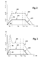
- FIGS. 2 and 3 are such An Kunststoffprofile AP1 to AP4 exemplified. They form the course of force F or current I of the motor of the belt tensioner 2 over the time t.
- Fig. 2 shows two drive profiles AP1 and AP2, each having two time periods tA1 and tB1.
- the force F or the current I increases in the form of a ramp R1, R2 to a force or current value F1, I1 or F2, I2, which remains constant in the second time interval tB2.
- the first time period tA1 forms the tensioning of the belt tensioner 2, the second time interval tB2 the holding of the belt tensioner 2 to a certain force.
- the drive profile AP1 has a smaller amplitude than the drive profile AP2, and is thus associated with a lower risk value.
- the ramps R1, R2 are different, but may also have a different shape.
- the continuously calculated danger value will form a lower danger level corresponding to a new control profile AP1 ', AP2'.
- a time interval tC1 is inserted which corresponds to a predefinable delay. Then the new first period tA2 starts.
- the new drive profile AP1 ', AP2' has the force value 0, so that a falling edge is generated, which can also have different shapes. Here is a sloping ramp shown.
- a hazard value assigned to the highest level of danger requires a rapid achievement of the highest level of force.
- the electric motor of the belt tensioner 2 can be driven with the greatest current intensity. This is exemplary in Fig. 3 shown with ramp R4 as a current peak of the drive profile AP4.
- the actuation profile AP3 corresponds to a lower danger value and is used here for comparison.
- FIGS. 2 and 3 in a second interpretation, for example, the relationship between the current intensity I of the belt tensioner 2 and the force generated thereby.
- the control profiles AP2 and AP4 are shown in dashed lines, and represent the current intensity I in connection with the respective control profiles AP 1 and AP3 (force curve F) drawn in a continuous curve underneath Fig. 2 recognize that at a force applied to the belt tensioner 2 current I with the drive profile AP2 with the ramp R2, a force profile F is generated with the drive profile AP 1 and the ramp R1.
- the Fig. 4 is an exemplary illustration of consecutive drive profiles AP1 to AP5. It is hereby intended to explain a sequence of different danger values with corresponding control profiles AP1 to AP5.
- the device 10 calculates a danger value which is updated by the calculation device 11 on the basis of continuously new acquired data of the sensor devices 3 to 9. Due to its danger level, the first danger value is assigned a first control profile AP1 with a first and second time interval tA1, tB1 and with a first force value F1. The danger value changes now to a higher danger level, wherein it is associated with a second drive profile AP2 with a first and second time period tA2, tB2 and with a second force value F2.
- the hazard value then changes to a lower danger level, with a time period tC2 being added to a time delay before the drive profile AP3 associated with the now current lower threat value having a first time period tA3 and a force value less than F2 is used.
- the danger value changes to the highest danger level, which triggers an immediate force increase in the first time interval tA4 of a following control profile AP4.
- the force value F2 then remains in the second time interval tB4 of the drive profile AP4 until the danger value changes to the lowest danger level. Therefore, a delay period tC4 follows before the lowest danger value drive profile AP5 decreases to the 0 force value in a second time period tB5 with a first time period tA5.
- a time counter is set before the first method step S1, and then the danger value is calculated in method step S1 on the basis of the sensors 3 to 9 described above.
- the calculated danger value is first compared with a predefinable threshold value for a first danger level G1. If this threshold is not exceeded, the hazard value is not classified as such. An already pre-tensioned belt tensioner is released again, it can be admitted for more comfort more slack. The time counter is increased by and it is again the current risk value in step S 1 calculated.
- a corresponding control profile AP is associated with the danger value in method step S3, with which the belt tensioner 2 is actuated as described above.
- danger levels G2 to G5 are differentiated: If the danger level has increased to the danger level G2, which forms the highest rating, a potential crash threatens. The belt slack must be eliminated immediately in this case, the engine of the reversible belt tensioner 2 is driven with maximum possible current. At a G3 danger level, there is no threat of a potential crash, but the forces acting on the occupants are so high that it would result in these movements if the occupant were not fixed. In this case, the belt force with a steep ramp R2 (see Fig. 2 ) built up quickly. In danger level G4, the risk is classified as medium to high, with lower forces than at hazard level G3.
- the (driver side) reversible belt tensioner 2 is controlled so that the belt force builds up gradually (ramp R1 in Fig. 2 ) to give the driver a feedback, that he is in a dangerous situation and must change his driving style accordingly.
- danger level G5 the danger is low to very low, there are only small forces, so that the belt tensioner, when it was biased, is released again for more comfort.
- the belt tensioner is driven at a relatively low risk value with a certain control profile, without the driver is disturbed, the number of potentially dangerous driving situations is not limited.
- the invention is not limited to the above-described embodiments, but modifiable in a variety of ways.
- a drive profile AP1 to AP5 has a different profile that, for example, certain curves are used instead of straight lines.
- the time intervals tA1..., TB1... Can also be subdivided into several sections with different profiles in order to achieve a particularly optimal adaptation.
- the calculated danger values and associated control profiles are stored in their temporal course in order to be retrieved subsequently by the driver via the display device 15 so that he can trace back the critical situations. This can also determine whether the vehicle has responded in a really uncritical situation, for example, due to component defects critical.
Landscapes
- Engineering & Computer Science (AREA)
- Mechanical Engineering (AREA)
- Automotive Seat Belt Assembly (AREA)
Claims (10)
- Procédé de commande d'au moins un moyen de retenue, en particulier d'un tendeur (2) de ceinture à moteur électrique d'un véhicule automobile, à l'aide d'un dispositif de commande (1), le procédé comportant les étapes suivantes :(S1) calcul par un dispositif de calcul (11) d'un indice de danger à l'aide de valeurs de données d'un ensemble de détecteurs (3...8) de la situation de conduite, de l'environnement et/ou des passagers du véhicule automobile,(S2) à l'aide de l'indice de danger, formation par une unité d'évaluation (12) d'un profil de commande (AP1...n) du tendeur (2) de ceinture et(S3) commande du tendeur (2) de ceinture au moyen du dispositif de commande (1) en fonction du profil de commande (AP1...n),caractérisé en ce que
à l'étape (S1) du traitement, lors du calcul d'un indice de danger qui présente un bas niveau de danger par rapport à un indice de danger précédent à haut niveau de danger, on utilise en supplément des valeurs de données d'une détection de collision (9) en même temps qu'un retard temporel prédéterminé,
en ce qu'à l'étape (S3) du procédé, un affichage est effectué à destination du conducteur en fonction de l'indice de danger et
en ce que l'évaluation des profils de commande qui correspondent à une situation de conduite critique est conservée en mémoire et est lue ultérieurement par l'intermédiaire de l'affichage et/ou d'une autre interface du dispositif de commande (1). - Procédé selon la revendication 1, caractérisé en ce que le profil de commande (AP1...n) définit l'évolution temporelle de la force (F) du tendeur (2) de ceinture à moteur électrique.
- Procédé selon la revendication 2, caractérisé en ce que le profil de commande (AP1...n) présente un premier intervalle de temps (tA1...n) qui active le tendeur (2) de ceinture par une force (F1, F2) définie et un deuxième intervalle de temps (tA1...n) qui maintient la force définie (F1, F2) sur le tendeur de ceinture.
- Procédé selon l'une des revendications 1 à 3, caractérisé en ce qu'à l'étape (S2) du procédé, l'indice de danger est comparé à des valeurs de seuil prédéterminées qui correspondent chacune à un niveau défini de danger (G1...n) et en ce que la formation du profil de commande (AP1...n) s'effectue à l'aide de la comparaison de valeurs de données prédéterminées et conservées en mémoire.
- Procédé selon la revendication 4, caractérisé en ce qu'à l'étape (S2) du procédé, lorsque l'indice de danger passe à un niveau de danger plus élevé, le profil de commande précédent (AP1...n) est remplacé immédiatement par le profil de commande (AP1...n) qui correspond au nouvel indice de danger et en ce que lorsque l'indice de danger passe à un niveau de danger plus bas, le profil de commande précédent (AP1...n) est remplacé après écoulement d'une durée prédéterminée par le profil de commande (AP1...n) qui correspond au nouvel indice de danger.
- Procédé selon la revendication 5, caractérisé en ce que la durée prédéterminée est calculée à l'étape (S1) du procédé.
- Procédé selon l'une des revendications 1 à 6, caractérisé en ce que dans l'étape (S3) du procédé, des signaux de commande qui commandent le tendeur (2) de ceinture à moteur électrique en modifiant le courant (1) de son moteur sont formés en fonction du profil de commande (AP1...n) concerné.
- Dispositif (10) de commande d'au moins un moyen de retenue réversible, en particulier d'un tendeur (2) de ceinture à moteur électrique, d'un véhicule automobile, qui présente un dispositif de commande (1), le dispositif (10) présentant les éléments suivants :- un dispositif de calcul (11) qui calcule un indice de danger à l'aide de valeurs de données d'un ensemble de détecteurs (3...9) de la situation de conduite, de l'environnement et des passagers du véhicule automobile,- un dispositif d'évaluation (12) qui forme un profil de commande (AP1...n) pour le tendeur (2) de ceinture à l'aide de l'indice de danger,- un dispositif de transfert (13) qui transfère le profil de commande (AP1...n) au dispositif de commande (1) qui commande le tendeur (2) de ceinture en fonction du profil de commande (AP1...n) etun dispositif de mémoire (14) qui conserve des valeurs de données prédéterminées,
caractérisé en ce que
le dispositif (10) présente un dispositif d'affichage (15) qui affiche au conducteur une indication qui est fonction de l'indice de danger,
en ce que l'évolution des profils de commande qui correspondent à une situation de conduite critique est conservée en mémoire et est lue ultérieurement par l'intermédiaire de l'affichage et/ou d'une autre interface du dispositif de commande (1) et
en ce que lorsque l'indice de danger calculé est à un niveau de danger plus bas qu'un indice de danger précédent à un plus haut niveau de danger, des valeurs de données supplémentaires d'une détection de collision sont utilisées en même temps qu'un retard temporel prédéterminé et en ce qu'un affichage à destination du conducteur est réalisé en fonction de l'indice de danger. - Dispositif selon la revendication 8, caractérisé en ce que le dispositif de transfert (13) présente un dispositif qui forme des signaux de commande qui commandent le tendeur (2) de ceinture à moteur électrique en modifiant le courant (I) de son moteur en fonction du profil de commande (AP1...n) particulier.
- Dispositif (10) selon l'une des revendications 8 à 9, caractérisé en ce que le dispositif (10) fait partie du dispositif de commande (1).
Applications Claiming Priority (1)
| Application Number | Priority Date | Filing Date | Title |
|---|---|---|---|
| DE200510038226 DE102005038226A1 (de) | 2005-08-12 | 2005-08-12 | Verfahren und Vorrichtung zum Ansteuern von zumindest einem Rückhaltemittel, insbesondere reversible Gurtstraffer, eines Kraftfahrzeugs |
Publications (2)
| Publication Number | Publication Date |
|---|---|
| EP1752339A1 EP1752339A1 (fr) | 2007-02-14 |
| EP1752339B1 true EP1752339B1 (fr) | 2011-09-14 |
Family
ID=37072242
Family Applications (1)
| Application Number | Title | Priority Date | Filing Date |
|---|---|---|---|
| EP20060117281 Not-in-force EP1752339B1 (fr) | 2005-08-12 | 2006-07-17 | Procédé et dispositif pour contrôler au moins un moyen de retenu, et en particulier un prétensionneur de ceinture de sécurité pour véhicule |
Country Status (3)
| Country | Link |
|---|---|
| EP (1) | EP1752339B1 (fr) |
| DE (1) | DE102005038226A1 (fr) |
| ES (1) | ES2369927T3 (fr) |
Cited By (1)
| Publication number | Priority date | Publication date | Assignee | Title |
|---|---|---|---|---|
| CN103600718A (zh) * | 2013-11-15 | 2014-02-26 | 郑州中智电子科技有限公司 | 一种安全带 |
Families Citing this family (17)
| Publication number | Priority date | Publication date | Assignee | Title |
|---|---|---|---|---|
| DE102008050316B4 (de) * | 2008-10-02 | 2015-06-25 | Daimler Ag | Verfahren und Vorrichtung zur dynamischen Fixierung eines Fahrzeuginsassen |
| DE102008050317A1 (de) * | 2008-10-02 | 2010-05-12 | Daimler Ag | Verfahren zur dynamischen Fixierung eines Fahrzeuginsassen |
| DE102009000656B9 (de) * | 2009-02-06 | 2018-05-09 | Robert Bosch Gmbh | Verfahren und Steuergerät zur Ansteuerung einer Sicherheitsaktuatorik eines Fahrzeugs |
| DE102010006107B4 (de) * | 2010-01-29 | 2019-12-19 | Bayerische Motoren Werke Aktiengesellschaft | Verfahren zur Ansteuerung eines Aktuators eines reversiblen Insassenschutzmittels in einem Kraftfahrzeug |
| DE102010003297B4 (de) | 2010-03-25 | 2015-12-10 | Bayerische Motoren Werke Aktiengesellschaft | Steuerung für ein Precrash-Sicherheitssystem in einem Kraftfahrzeug |
| DE102010015547B4 (de) | 2010-04-20 | 2020-07-30 | Daimler Ag | Verfahren zur Ansteuerung mindestens einer reversiblen Insassenschutzvorrichtung |
| DE102010053962B4 (de) * | 2010-12-09 | 2020-03-05 | Daimler Ag | Verfahren und eine Vorrichtung zur Ansteuerung mindestens eines Insassenschutzmittels eines Fahrzeuges |
| DE102011106247B4 (de) * | 2011-07-01 | 2014-05-28 | Audi Ag | Verfahren zum Steuern eines reversiblen Gurtstraffers eines Sicherheitsgurts in einem Kraftfahrzeug |
| DE102011082067A1 (de) * | 2011-09-02 | 2013-03-07 | Robert Bosch Gmbh | Verfahren zum Ansteuern von Sicherheitsaktuatorik eines Kraftfahrzeugs |
| DE102011084204A1 (de) * | 2011-10-10 | 2013-04-11 | Robert Bosch Gmbh | Verfahren zum Ansteuern von Sicherheitsaktuatorik eines Kraftfahrzeugs |
| DE102011087698B4 (de) | 2011-12-05 | 2022-02-24 | Robert Bosch Gmbh | Verfahren zum Ansteuern eines Insassenschutzmittels eines Fahrzeugs und Steuergerät |
| DE102012107188B4 (de) * | 2012-08-06 | 2022-06-15 | Continental Automotive Gmbh | Verfahren zur Aktivierung von Schutzmaßnahmen in Fahrzeugen beim Erkennen einer Gefährdungssituation |
| DE102014200813B4 (de) * | 2014-01-17 | 2022-04-21 | Volkswagen Aktiengesellschaft | Verfahren und Vorrichtung zur Auslösung eines adaptiven Rückhaltesystems |
| DE102014223618B4 (de) * | 2014-11-19 | 2019-12-19 | Robert Bosch Gmbh | Verfahren zum Betreiben einer Sicherheitsvorrichtung eines Kraftfahrzeugs |
| DE102016213915B4 (de) * | 2016-07-28 | 2025-05-08 | Robert Bosch Gmbh | Rückhaltesystem für ein Insassenschutzsystem eines Fahrzeugs |
| KR102626248B1 (ko) | 2017-12-11 | 2024-01-17 | 현대자동차주식회사 | 능동형 안전 벨트 제어 장치 및 이의 제어 방법 |
| JP7172941B2 (ja) * | 2019-10-07 | 2022-11-16 | トヨタ自動車株式会社 | 車両用乗員拘束システム |
Family Cites Families (5)
| Publication number | Priority date | Publication date | Assignee | Title |
|---|---|---|---|---|
| GB2335890B (en) * | 1997-12-16 | 2002-05-29 | Nsk Ltd | Automotive passenger restraint and protection apparatus and seatbelt protraction and retraction amount detecting device |
| DE10005010C2 (de) | 2000-02-04 | 2002-11-21 | Daimler Chrysler Ag | Verfahren und Sicherheits-Rückhalteeinrichtung zum Zurückhalten eines Insassen auf einem Fahrzeugsitz |
| DE10029061C2 (de) | 2000-06-13 | 2003-12-11 | Breed Automotive Tech | Rückhaltevorrichtung |
| DE10121386C1 (de) | 2001-05-02 | 2002-08-29 | Daimler Chrysler Ag | Verfahren zum Ansteuern eines reversiblen Insassenschutzmittels in einem Kraftfahrzeug |
| JP3912260B2 (ja) * | 2002-10-31 | 2007-05-09 | 日産自動車株式会社 | 車両用シートベルト装置 |
-
2005
- 2005-08-12 DE DE200510038226 patent/DE102005038226A1/de not_active Withdrawn
-
2006
- 2006-07-17 EP EP20060117281 patent/EP1752339B1/fr not_active Not-in-force
- 2006-07-17 ES ES06117281T patent/ES2369927T3/es active Active
Cited By (1)
| Publication number | Priority date | Publication date | Assignee | Title |
|---|---|---|---|---|
| CN103600718A (zh) * | 2013-11-15 | 2014-02-26 | 郑州中智电子科技有限公司 | 一种安全带 |
Also Published As
| Publication number | Publication date |
|---|---|
| ES2369927T3 (es) | 2011-12-09 |
| DE102005038226A1 (de) | 2007-02-15 |
| EP1752339A1 (fr) | 2007-02-14 |
Similar Documents
| Publication | Publication Date | Title |
|---|---|---|
| EP1752339B1 (fr) | Procédé et dispositif pour contrôler au moins un moyen de retenu, et en particulier un prétensionneur de ceinture de sécurité pour véhicule | |
| DE102004057604B4 (de) | Verfahren für ein Sicherheitssystem in einem Fahrzeug | |
| EP1843924B1 (fr) | Procede et dispositif pour eviter et/ou reduire les consequences de collisions en cas d'evitement d'obstacles | |
| EP1530527B1 (fr) | Procede et dispositif pour declencher automatiquement un processus de freinage d'urgence dans un vehicule | |
| EP1720739B1 (fr) | Dispositif pour determiner une tendance au basculement | |
| EP1901941B1 (fr) | Procede et dispositif de commande d'un moyen de protection d'un passager | |
| DE112016006035T5 (de) | Fahrzeugsteuerungsvorrichtung und Fahrzeugsteuerungsverfahren | |
| EP1409311A1 (fr) | Procede et dispositif pour declencher et executer une deceleration d'un vehicule | |
| DE102009033891A1 (de) | Sicherheitssteuerungsvorrichtung zum Einbau in ein Fahrzeug | |
| EP1034985A2 (fr) | Méthode et dispositif de commande d'un système de retenue d' un véhicule | |
| DE102010029223B4 (de) | Bremsassistent für Kraftfahrzeuge mit verbesserter Bremswirkung | |
| DE102017209533A1 (de) | Spurwechselassistenzsystem und Spurwechselassistenzverfahren mit erhöhter Sicherheit für den Fahrer und andere Verkehrsteilnehmer | |
| DE102004057603A1 (de) | Verfahren für ein Sicherheitssystem in einem Fahrzeug | |
| DE102008040038A1 (de) | Heckaufprall-Precrash-und Crash-System | |
| DE102013021270A1 (de) | Verfahren zum Betrieb eines Fahrzeuges | |
| DE102004018394B4 (de) | Insassenschutzsystem | |
| EP1932735A2 (fr) | Procédé et système d'empêchement de collisions multiples et d'atténuation de leurs effects | |
| EP2054280B1 (fr) | Commande de moyens de sécurité d'un véhicule automobile | |
| EP2900528B1 (fr) | Procédé et dispositif pour le fonctionnement d'un véhicule et véhicule équipé d'un tel dispositif | |
| DE102005027845B4 (de) | Verfahren zur Steuerung der Bremsanlage eines stehenden oder beinahe stehenden Fahrzeugs | |
| EP3363705B1 (fr) | Procédé d'activation d'au moins une fonction d'un véhicule automobile, système d'aide à la conduite et véhicule automobile | |
| DE102010015547A1 (de) | Verfahren zur Ansteuerung mindestens einer reversiblen Insassenschutzvorrichtung | |
| DE102004028160A1 (de) | Bremssystem mit Bremsassistent | |
| DE102022111723A1 (de) | Verfahren, computerprogrammprodukt, fahrassistenzsystem und fahrzeug | |
| DE102010019552B4 (de) | Verfahren zur Ansteuerung mindestens eines Insassenschutzmittels eines Fahrzeuges |
Legal Events
| Date | Code | Title | Description |
|---|---|---|---|
| PUAI | Public reference made under article 153(3) epc to a published international application that has entered the european phase |
Free format text: ORIGINAL CODE: 0009012 |
|
| AK | Designated contracting states |
Kind code of ref document: A1 Designated state(s): AT BE BG CH CY CZ DE DK EE ES FI FR GB GR HU IE IS IT LI LT LU LV MC NL PL PT RO SE SI SK TR |
|
| AX | Request for extension of the european patent |
Extension state: AL BA HR MK YU |
|
| 17P | Request for examination filed |
Effective date: 20070814 |
|
| AKX | Designation fees paid |
Designated state(s): DE ES FR GB |
|
| 17Q | First examination report despatched |
Effective date: 20070926 |
|
| GRAP | Despatch of communication of intention to grant a patent |
Free format text: ORIGINAL CODE: EPIDOSNIGR1 |
|
| GRAS | Grant fee paid |
Free format text: ORIGINAL CODE: EPIDOSNIGR3 |
|
| RTI1 | Title (correction) |
Free format text: METHOD AND DEVICE FOR CONTROLLING AT LEAST ONE RESTRAINING MEANS, IN PARTICULAR A SEAT BELT PRETENTIONER |
|
| GRAA | (expected) grant |
Free format text: ORIGINAL CODE: 0009210 |
|
| AK | Designated contracting states |
Kind code of ref document: B1 Designated state(s): DE ES FR GB |
|
| REG | Reference to a national code |
Ref country code: GB Ref legal event code: FG4D Free format text: NOT ENGLISH |
|
| REG | Reference to a national code |
Ref country code: DE Ref legal event code: R096 Ref document number: 502006010161 Country of ref document: DE Effective date: 20111110 |
|
| REG | Reference to a national code |
Ref country code: ES Ref legal event code: FG2A Ref document number: 2369927 Country of ref document: ES Kind code of ref document: T3 Effective date: 20111209 |
|
| PLBE | No opposition filed within time limit |
Free format text: ORIGINAL CODE: 0009261 |
|
| STAA | Information on the status of an ep patent application or granted ep patent |
Free format text: STATUS: NO OPPOSITION FILED WITHIN TIME LIMIT |
|
| 26N | No opposition filed |
Effective date: 20120615 |
|
| REG | Reference to a national code |
Ref country code: DE Ref legal event code: R097 Ref document number: 502006010161 Country of ref document: DE Effective date: 20120615 |
|
| REG | Reference to a national code |
Ref country code: FR Ref legal event code: PLFP Year of fee payment: 11 |
|
| PGFP | Annual fee paid to national office [announced via postgrant information from national office to epo] |
Ref country code: GB Payment date: 20160722 Year of fee payment: 11 |
|
| PGFP | Annual fee paid to national office [announced via postgrant information from national office to epo] |
Ref country code: FR Payment date: 20160722 Year of fee payment: 11 |
|
| PGFP | Annual fee paid to national office [announced via postgrant information from national office to epo] |
Ref country code: ES Payment date: 20160722 Year of fee payment: 11 |
|
| GBPC | Gb: european patent ceased through non-payment of renewal fee |
Effective date: 20170717 |
|
| REG | Reference to a national code |
Ref country code: FR Ref legal event code: ST Effective date: 20180330 |
|
| PG25 | Lapsed in a contracting state [announced via postgrant information from national office to epo] |
Ref country code: GB Free format text: LAPSE BECAUSE OF NON-PAYMENT OF DUE FEES Effective date: 20170717 |
|
| PG25 | Lapsed in a contracting state [announced via postgrant information from national office to epo] |
Ref country code: FR Free format text: LAPSE BECAUSE OF NON-PAYMENT OF DUE FEES Effective date: 20170731 |
|
| REG | Reference to a national code |
Ref country code: ES Ref legal event code: FD2A Effective date: 20181106 |
|
| PGFP | Annual fee paid to national office [announced via postgrant information from national office to epo] |
Ref country code: DE Payment date: 20180928 Year of fee payment: 13 |
|
| PG25 | Lapsed in a contracting state [announced via postgrant information from national office to epo] |
Ref country code: ES Free format text: LAPSE BECAUSE OF NON-PAYMENT OF DUE FEES Effective date: 20170718 |
|
| REG | Reference to a national code |
Ref country code: DE Ref legal event code: R119 Ref document number: 502006010161 Country of ref document: DE |
|
| PG25 | Lapsed in a contracting state [announced via postgrant information from national office to epo] |
Ref country code: DE Free format text: LAPSE BECAUSE OF NON-PAYMENT OF DUE FEES Effective date: 20200201 |