EP1752390B1 - Verwendung eines verpackungsmaterials und verfahren für den transport eines wabenförmig strukturierten körpers - Google Patents
Verwendung eines verpackungsmaterials und verfahren für den transport eines wabenförmig strukturierten körpers Download PDFInfo
- Publication number
- EP1752390B1 EP1752390B1 EP06715001A EP06715001A EP1752390B1 EP 1752390 B1 EP1752390 B1 EP 1752390B1 EP 06715001 A EP06715001 A EP 06715001A EP 06715001 A EP06715001 A EP 06715001A EP 1752390 B1 EP1752390 B1 EP 1752390B1
- Authority
- EP
- European Patent Office
- Prior art keywords
- packaging material
- polypropylene
- face
- structured body
- honeycomb structured
- Prior art date
- Legal status (The legal status is an assumption and is not a legal conclusion. Google has not performed a legal analysis and makes no representation as to the accuracy of the status listed.)
- Expired - Lifetime
Links
Images





Classifications
-
- B—PERFORMING OPERATIONS; TRANSPORTING
- B65—CONVEYING; PACKING; STORING; HANDLING THIN OR FILAMENTARY MATERIAL
- B65D—CONTAINERS FOR STORAGE OR TRANSPORT OF ARTICLES OR MATERIALS, e.g. BAGS, BARRELS, BOTTLES, BOXES, CANS, CARTONS, CRATES, DRUMS, JARS, TANKS, HOPPERS, FORWARDING CONTAINERS; ACCESSORIES, CLOSURES, OR FITTINGS THEREFOR; PACKAGING ELEMENTS; PACKAGES
- B65D71/00—Bundles of articles held together by packaging elements for convenience of storage or transport, e.g. portable segregating carrier for plural receptacles such as beer cans or pop bottles; Bales of material
- B65D71/70—Trays provided with projections or recesses in order to assemble multiple articles, e.g. intermediate elements for stacking
-
- B—PERFORMING OPERATIONS; TRANSPORTING
- B65—CONVEYING; PACKING; STORING; HANDLING THIN OR FILAMENTARY MATERIAL
- B65D—CONTAINERS FOR STORAGE OR TRANSPORT OF ARTICLES OR MATERIALS, e.g. BAGS, BARRELS, BOTTLES, BOXES, CANS, CARTONS, CRATES, DRUMS, JARS, TANKS, HOPPERS, FORWARDING CONTAINERS; ACCESSORIES, CLOSURES, OR FITTINGS THEREFOR; PACKAGING ELEMENTS; PACKAGES
- B65D71/00—Bundles of articles held together by packaging elements for convenience of storage or transport, e.g. portable segregating carrier for plural receptacles such as beer cans or pop bottles; Bales of material
- B65D71/70—Trays provided with projections or recesses in order to assemble multiple articles, e.g. intermediate elements for stacking
- B65D71/72—Trays provided with projections or recesses in order to assemble multiple articles, e.g. intermediate elements for stacking formed by folding one or more blanks, the articles being inserted in openings in a wall
-
- B—PERFORMING OPERATIONS; TRANSPORTING
- B65—CONVEYING; PACKING; STORING; HANDLING THIN OR FILAMENTARY MATERIAL
- B65D—CONTAINERS FOR STORAGE OR TRANSPORT OF ARTICLES OR MATERIALS, e.g. BAGS, BARRELS, BOTTLES, BOXES, CANS, CARTONS, CRATES, DRUMS, JARS, TANKS, HOPPERS, FORWARDING CONTAINERS; ACCESSORIES, CLOSURES, OR FITTINGS THEREFOR; PACKAGING ELEMENTS; PACKAGES
- B65D81/00—Containers, packaging elements, or packages, for contents presenting particular transport or storage problems, or adapted to be used for non-packaging purposes after removal of contents
- B65D81/02—Containers, packaging elements, or packages, for contents presenting particular transport or storage problems, or adapted to be used for non-packaging purposes after removal of contents specially adapted to protect contents from mechanical damage
- B65D81/05—Containers, packaging elements, or packages, for contents presenting particular transport or storage problems, or adapted to be used for non-packaging purposes after removal of contents specially adapted to protect contents from mechanical damage maintaining contents at spaced relation from package walls, or from other contents
- B65D81/107—Containers, packaging elements, or packages, for contents presenting particular transport or storage problems, or adapted to be used for non-packaging purposes after removal of contents specially adapted to protect contents from mechanical damage maintaining contents at spaced relation from package walls, or from other contents using blocks of shock-absorbing material
- B65D81/113—Containers, packaging elements, or packages, for contents presenting particular transport or storage problems, or adapted to be used for non-packaging purposes after removal of contents specially adapted to protect contents from mechanical damage maintaining contents at spaced relation from package walls, or from other contents using blocks of shock-absorbing material of a shape specially adapted to accommodate contents
-
- B—PERFORMING OPERATIONS; TRANSPORTING
- B65—CONVEYING; PACKING; STORING; HANDLING THIN OR FILAMENTARY MATERIAL
- B65D—CONTAINERS FOR STORAGE OR TRANSPORT OF ARTICLES OR MATERIALS, e.g. BAGS, BARRELS, BOTTLES, BOXES, CANS, CARTONS, CRATES, DRUMS, JARS, TANKS, HOPPERS, FORWARDING CONTAINERS; ACCESSORIES, CLOSURES, OR FITTINGS THEREFOR; PACKAGING ELEMENTS; PACKAGES
- B65D2301/00—Details of blanks
- B65D2301/20—Details of blanks made of plastic material
-
- Y—GENERAL TAGGING OF NEW TECHNOLOGICAL DEVELOPMENTS; GENERAL TAGGING OF CROSS-SECTIONAL TECHNOLOGIES SPANNING OVER SEVERAL SECTIONS OF THE IPC; TECHNICAL SUBJECTS COVERED BY FORMER USPC CROSS-REFERENCE ART COLLECTIONS [XRACs] AND DIGESTS
- Y10—TECHNICAL SUBJECTS COVERED BY FORMER USPC
- Y10T—TECHNICAL SUBJECTS COVERED BY FORMER US CLASSIFICATION
- Y10T428/00—Stock material or miscellaneous articles
- Y10T428/24—Structurally defined web or sheet [e.g., overall dimension, etc.]
- Y10T428/24149—Honeycomb-like
Definitions
- the present invention relates to the use of a packaging material for packaging a honeycomb structured body according to the preamble of claim 1 and to a method of transporting a honeycomb structured body according to the preamble of claim 7.
- particulates such as soot contained in exhaust gases that are discharged from internal combustion engines of vehicles, such as buses and trucks, and construction machines, have raised serious problems as contaminants harmful to the environment and the human body.
- the honeycomb structured body of this kind is mainly composed of a porous ceramic material that is a fragile material, and thus it can be damaged due to external impact applied upon transportation or the like.
- various packaging materials and holding plates for honeycomb structural bodies have been proposed so as to protect the honeycomb structured body from external impact or the like (for example, see Patent Document 1 and Patent Document 2).
- the inventors of the present invention have studied hard, and have newly found a packaging material that can prevent positional displacement and bending, and a method of transporting a honeycomb structured body in which the packaging material is used, thereby completing the present invention.
- This object is solved with use of a packaging material according to claim 1 and a method for transporting according to claim 7.
- the reinforcing portion is preferably formed by forming a groove and/or a concave portion in the plate member. Moreover, the installation portion is formed by forming a bottomed hole in the plate member.
- the installation area for the object to be packaged in the bottomed hole is preferably smaller than the opening area of the bottomed hole.
- the bottomed hole preferably has such a shape that, when an object to be packaged is placed therein, a gap is formed between the bottomed hole and the object to be packaged.
- the packaging material in accordance with an embodiment which is not part of the invention comprises a plate member, packages an object to be packaged by sandwiching the object, and has a structure in which the plate member is provided with an installation portion for the object to be packaged comprising a bottomed hole, and the installation area for the object to be packaged in the bottomed hole is smaller than the opening area of the bottomed hole.
- a packaging material in accordance with an embodiment which is not part of the invention is a packaging material, which comprises a plate member, packages an object to be packaged by sandwiching the object, and has a structure in which the plate member is provided with an installation portion for the object to be packaged comprising a bottomed hole, and the bottomed hole has such a shape that, when an object to be packaged is placed therein, a gap is formed between the bottomed hole and the object to be packaged.
- a packaging material in accordance with an embodiment which is not part of the invention is a packaging material, which packages an object to be packaged by sandwiching the object, comprising:
- a packaging material in accordance with an embodiment which is not part of the invention is a packaging material used for packaging a pillar-shaped object to be packaged, which comprises:
- the reinforcing portion is preferably formed by forming a groove and/or a concave portion in the plate member.
- the installation portion is formed by forming a bottomed hole in the plate member.
- the installation area for the object to be packaged in the bottomed hole is preferably smaller than the opening area of the bottomed hole.
- the bottomed hole preferably has such a shape that, when an object to be packaged is placed therein, a gap is formed between the bottomed hole and the object to be packaged.
- the method of transporting a honeycomb structured body in accordance with an embodiment which is not part of the invention comprises housing the honeycomb structured body packaged with a packaging material in a box member, and then transporting the box member, and in this method, the packaging material, which comprises a plate member, is a packaging material for packaging an object to be packaged by sandwiching the object; the plate member is provided with an installation portion for the object to be packaged comprising a bottomed hole; and the bottomed hole has such a shape that, when an object to be packaged is placed therein, a gap is formed between the bottomed hole and the object to be packaged.
- the packaging material hardly bends even upon receipt of an externally applied impact or the like. Consequently, damage such as cracks does not occur in an object to be packaged that has been packaged by this packaging material. Thus, it becomes possible to reduce the rate of occurrence of the damage at the time of transporting the packaged object.
- the packaging material of the present invention will be explained by taking an example of the case where a honeycomb structured body is used as an object to be packaged; however, the object which can be packaged with the packaging material of the present invention is not limited to the honeycomb structured body.
- the packaging material according to the present invention which comprises a plate member, packages an object to be packaged by sandwiching the object, and the plate member is provided with an installation portion for the object to be packaged and provided as well with a reinforcing portion.
- the following description will discuss a specific embodiment of the packaging material according to the present invention.
- the specific embodiment of the packaging material according to the present invention is not limited to the embodiments shown in the drawings.
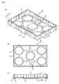
- Fig. 1 (a) is a perspective view that schematically shows one example of a packaging material which is not part of the present invention
- Fig. 1(b) is a plan view showing the packaging material shown in Fig. 1(a)
- Fig. 1(c) is a cross-sectional view taken along line A-A of the packaging material shown in Fig. 1(a)
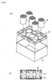
- Fig. 2 (a) is an exploded perspective view that explains an embodiment in which a honeycomb structured body is packaged with a packaging material 10 shown in Fig. 1 and further housed in a box member
- Fig. 2(b) is a cross-sectional view of the embodiment shown in Fig. 2(a) .
- the packaging material 10, shown in Fig. 1 is a packaging material formed by molding a plastic sheet, and has a structure in which an installation portion 11 used for installing the end face neighborhood of an object to be packaged (honeycomb structured body) is formed on its upper face and a plurality of reinforcing portions (installation-face reinforcing portions) 12 are secured to a part of the area where no installation portion 11 is formed.
- the reinforcing portions 12 are secured in such a manner that, when each of them crosses the other reinforcing portion, the two portions are orthogonal to each other.
- a peripheral side face portion 14, formed by bending the plastic sheet upward, is formed on the peripheral portion of the packing member 10, and a plurality of grooves 15 are formed in the peripheral side face portion 14.
- the grooves 15 are also allowed to function as reinforcing portions (side face reinforcing portions).
- the installation portion 11 is formed in such a manner that the diameter (upper face diameter) of the upper face portion is made smaller than the diameter of the end face of the honeycomb structured body, and a side face 11a thereof is formed in a tapered shape with its diameter increasing toward the bottom face.
- the installation portion 11 is formed in a size that holds only one portion of the end face of the honeycomb structured body. In other words, the diameter of the upper face (indicated by L in the figure) of the installation portion 11 is made shorter than the diameter of the end face of the honeycomb structured body.
- Fig. 2 Upon packaging a honeycomb structured body 20 by using the packaging material 10, as shown in Fig. 2 , the end face neighborhood of the honeycomb structured body 20 is placed on the installation portion 11, and the packaging material 10 in which the honeycomb structured body 20 has been packaged is housed in the box member 21.
- the packaging material 10 in which the honeycomb structured body 20 has been packaged is housed in the box member 21.
- the box member 21 not only the lower side of the honeycomb structured body 20, but also the upper side thereof is packaged with the packaging materials (see Fig. 2(b) ).
- the end face neighborhood of the honeycomb structured body 20 on the upper side is held by the packaging material 10 in its upside down state.
- Fig. 2 (a) shows only the packaging material for the lower side of the honeycomb structured body
- FIG. 2(b) shows a state in which the upper and lower sides of the honeycomb structured body are packaged with the packaging materials.
- the upper face diameter (L in Fig. 1 ) and the bottom diameter (M in Fig. 1 ) of the installation portion 11 are respectively determined by the diameter of the end face of the honeycomb structured body, and the upper face diameter is preferably shorter than the diameter of the end face of the honeycomb structured body by about 2 to 40 mm, while the bottom diameter is preferably longer than the diameter of the end face of the honeycomb structured body by about 5 to 20 mm.
- the height of the installation portion 11 is about in a range from 1 to 10 mm when packaging a honeycomb structured body having a diameter of 145 mm and a length of 150 mm, for example.
- Irregularities may be formed on the installation portion 11.
- the irregularities having a surface roughness Ra of 0.1 ⁇ m or more are formed, the coefficient of friction between an object to be packaged and the installation portion can be increased so that displacement (slippage) of the object to be packaged can be prevented.
- the irregularities of 1 mm or more for example, grooves or the like
- a function of preventing deformation of the installation portion itself can be rendered thereto.
- reinforcing portions 12 are formed at an area of the installation face where the installation portions 11 are not formed.
- the formation of such reinforcing portions 12 makes it possible to prevent the packaging material 10 from being bent at the time of transportation or the like, and consequently to prevent the honeycomb structured body from being damaged.
- the reinforcing portions 12 are preferably formed in such a manner that, when each reinforcing portion 12 intersects with another reinforcing portion 12, those reinforcing portions are orthogonal to each other.
- the reinforcing portions 12 are formed so as to be orthogonal to each other, the strength of the packaging material is improved so that it is possible to surely prevent the packaging material from being bent.
- the installation portions and reinforcing portions are formed by processing the plastic sheet; that is, the entire portion is formed by the same material, and on the other hand, a base portion (the portion other than the reinforcing portions) may be formed by processing the plastic sheet or the like, and the reinforcing portions may be formed using another material (see Figs. 3 and 4 ).
- the reinforcing portions may be formed by using a material that is comparatively more resistant against deformation than a material constituting the base portion, and specific examples of the material include: wood, metal, cardboard, styrofoam, and the like.
- Plastics may be used as the material for the reinforcing portions, and in this case, plastic materials of a kind that are highly resistant against deformation are preferably used.
- a peripheral side face portion 14 is formed on the peripheral portion of the packaging material 10.
- the contact area between the packaging material 10 and the inner face of the box member 21 is increased when the packaging material 10 is housed in the box member 21, thereby risk of displacement or bending of packaging material 10 inside the box member is decreased, and consequently damage is less likely to occur in the honeycomb structured body.
- grooves (side face reinforcing portions) 15, which function as reinforcing portion, are formed in the peripheral side face portion 14; thus, the formation of these grooves 15 further increases the strength of the peripheral side face portion 14, thereby further reducing the chance of displacement or bending of the packaging material.
- the grooves 15 of the peripheral side face portion 14 may be formed on demand.
- the grooves 15 are formed on the peripheral side face as the reinforcing portions; however, in place of the grooves 15, concave portions may be formed on the peripheral side face.
- reinforcing members made of wood, metal, plastics, cardboard, styrofoam or the like, may be secured to the positions in the peripheral side face corresponding to positions for the grooves and concave portions so that the reinforcing portions may be formed.
- the grooves refer to those grooves formed over the entire peripheral side face in the height direction (see Fig. 1 )
- the concave portions refer to those concave portions formed only on part of the peripheral side face in the height direction (see Fig. 4 ).
- the shape of the installation portion 11 is a truncated cone shape; however, the shape of the installation portion is not limited to the truncated cone shape.
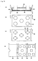
- Fig. 12 (a) is a plan view that schematically shows another example of the packaging material, and Fig. 12 (b) is a cross-sectional view taken along line A-A of the packaging material shown in Fig. 12 (a) .
- the shape of the packaging material 110 shown in Fig. 12 is the same as that of the packaging material 10 shown in Fig. 1 , except that the shape of the installation portion 111 is different; therefore, the description thereof is omitted.
- the packaging material may have shapes, for example, as shown in Figs. 3 and 4 .
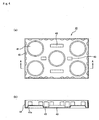
- Figs. 3 (a) and 4 (a) are plan views that schematically show other examples of the packaging material
- Figs. 3 (b) and 4 (b) are cross-sectional views taken along line A-A of the packaging materials shown in Figs. 3(a) and 4(a) , respectively.
- the packaging material 30, shown in Fig. 3 is a packaging material formed by molding a plastic sheet, and has a structure in which an installation portion 31 used for installing the end face neighborhood of an object to be packaged (honeycomb structured body) is formed on its upper face. Moreover, a plurality of reinforcing portions (installation-face reinforcing portions) 32 are secured to a part of a face opposite to the face on which the installation portion 31 of a plastic sheet is formed.
- the reinforcing portions 32 are formed in such a manner that when each of them crosses the other reinforcing portion, the two portions are orthogonal to each other.
- the embodiment of the peripheral side face 34 of the packaging material 30 shown in Fig. 3 is the same as that of the packaging material 10 shown in Fig. 1 , except that no grooves serving as reinforcing portions are formed thereon.
- the use of the packaging material 30 can also prevent displacement and bending of the packaging material at the time when a honeycomb structured body is packaged, housed in a box member, and transported or the like, and consequently prevents the honeycomb structured body from being, for example, damaged.
- the shape of the installation portion 31 is the same as that in the aforementioned packaging material 10; therefore, the description thereof is omitted.
- the packaging material 40 shown in Fig. 4 is a packaging material formed by molding a plastic sheet, and has a structure in which installation portions 41, each used for installing the end face neighborhood of an object to be packaged (honeycomb structured body), are formed on its upper face, and a plurality of reinforcing portions (installation-face reinforcing portions) 43 are secured to apart of an area where no installation portions 41 are formed, on the same face on which the installation portions 41 have been formed.
- a peripheral side face 44 formed by bending a plastic sheet upward, is formed on the peripheral portion of the packing member 40, and a plurality of concave portions 45 are formed on the peripheral side face 44.
- the concave portions 45 are also allowed to function as reinforcing portions.
- the embodiment of the packaging material 40 shown in Fig. 4 is the same as that of the packaging material 10 shown in Fig. 1 , except that the shape of the reinforcing members 43 is different.
- the reinforcing portions 43 have a function of preventing the packaging material 30 from being bent, in the same manner as the reinforcing portions 12 formed in the packaging material 10.
- the use of the packaging material 40 can also prevent displacement and bending of the packaging material at the time when the honeycomb structured body is packaged, housed in the box member and transported, and consequently prevents the honeycomb structured body from being, for example, damaged.
- the shape of the installation portion 41 is the same as that of the aforementioned packaging material 10; therefore, the description thereof is omitted.
- each of the above-mentioned installation portions may be formed by forming a bottomed hole in the plate member.
- the installation area for the object to be packaged in the bottomed hole is desirably smaller than the opening area of the bottomed hole.
- the bottomed hole is preferably formed into a shape in which, when the object to be packaged is placed thereon, a gap is formed between the bottomed hole and the object to be packaged.
- Fig. 5 (a) is a perspective view that schematically shows one example of a packaging material in accordance with the present invention
- Fig. 5 (b) is a plan view showing the packaging material shown in Fig. 5 (a)
- Fig. 5(c) is a cross-sectional view taken along line A-A of the packaging material of Fig. 5(a)
- Fig. 6(a) is an exploded perspective view that explains an embodiment in which a honeycomb structured body is packaged with a packaging material 50 shown in Fig. 5 and further housed in a box member
- Fig. 6 (b) is a cross-sectional view of the embodiment shown in Fig. 6(a) .
- the packaging material 50 shown in Fig. 5 is a packaging material formed by molding a plastic sheet, and has a structure in which bottomed holes 51, each used for installing the end face neighborhood of an object to be packaged (honeycomb structured body), are formed on its upper face, and a plurality of grooves (installation-face reinforcing portions) 52 are secured to a part of an area where no bottomed hole 51 is formed.
- the grooves 52 are secured in such a manner that when each of them crosses another groove, the two grooves are orthogonal to each other.
- a peripheral side face 54 formed by bending a plastic sheet downward, is formed on the peripheral portion of the packing member 50, and a plurality of grooves (side-face reinforcing portions) 55 are formed on the peripheral side face 54.
- the grooves 52 and 55 are also allowed to function as reinforcing portions.
- Each bottomed hole 51 is formed in such a manner that the diameter of the opening portion is larger than the diameter of the end face of a honeycomb structured body, and its side face 51a is formed into a tapered shape having the diameter decreasing toward the bottom face, and a raised bottom portion (installation portion) 56, which holds the end face of the honeycomb structured body, is formed on the bottom face.
- the raised bottom portion 56 is shaped into a size that supports only a part of the end face of the honeycomb structured body. In other words, the diameter of the upper face (indicated by L in Fig. 5(c) ) of the raised bottom portion 56 is shorter than the diameter of the end face of the honeycomb structured body.
- the installation area for the honeycomb structured body in the bottomed hole 51 is smaller than the opening area of the bottomed hole 51, and in the packaging material 50 having such bottomed holes 51, only a part of the end face of the honeycomb structured body is made in contact with the installation portion so that damage is far less likely to occur in the honeycomb structured body at the time of a transporting process or the like.
- the end face neighborhood of the honeycomb structured body is housed in each bottomed hole 51, and the packaging material 50 in which the honeycomb structured body 20 has been packaged is housed in the box member 21.
- the box member 21 normally, not only the lower side of the honeycomb structured body 20, but also the upper side thereof is packaged with the packaging material. In other words, the end face neighborhood of the honeycomb structured body 20 on the upper side is held by the packaging material 50 in its upside down state.
- the raised bottom portion 56 is formed on the bottom face of each bottomed hole 51. As shown in Fig. 6 , at the time of a transporting process or the like of the packaging material 50 and the honeycomb structured body 20, both housed in the box member 21, the formation of such a raised bottom portion 56 makes it possible to prevent the honeycomb structured body from being damaged due to impact from below.
- the opening diameter and the bottom diameter of the bottomed hole 51 are respectively determined according to the diameter of the end face of the honeycomb structured body, and the opening diameter is preferably made longer than the diameter of the end face of the honeycomb structured body by about 5 mm to 20 mm, while the bottom diameter is preferably made shorter than the diameter of the end face of the honeycomb structured body by about 2 mm to 10 mm.
- the depth of the bottomed hole 51 and the raised height of the raised bottom portion 56 are set in a range from 20 mm to 50 mm and in a range from 1 to 10 mm, respectively, in the case where, for example, a honeycomb structured body having ⁇ 145 mm and a length of 150 mm is packaged.
- the upper face diameter (L, in Fig. 5 ) of the raised bottom portion 56 may be applicable as long as it is shorter than the diameter of the end face of the honeycomb structured body, and by ordinary, it is desirably shorter by 5 mm to 40 mm.
- Grooves 52 are formed in an area of the packaging material 50 where no bottomed hole 51 is formed.
- the formation of these grooves 52 makes it possible to prevent the packaging material 50 from being bent at the time of a transporting process or the like, and consequently to prevent the honeycomb structured body from being damaged.
- the grooves 52 are preferably formed in such a manner that when each of them crosses another groove, the two grooves are orthogonal to each other.
- the grooves 52 are formed so as to be orthogonal to each other in this manner, the strength of the packaging material is improved so that it ispossible to certainly prevent the packaging material from being bent.
- a peripheral side face 54 is formed on the peripheral portion of the packing member 50.
- the contact area between the packaging material 50 and the inner face of the box member 21 is increased when the packaging material 50 is housed in the box member 21, thereby making it possible to prevent the packaging material 50 from being displaced or bent inside the box member, and consequently damage becomes less likely to occur in the honeycomb structured body.
- grooves 55 which function as reinforcing portions, are formed on the peripheral side face 54, and the formation of these grooves 55 further increases the strength of the peripheral side face 54, thereby further preventing the packaging material from being displaced and bent.
- grooves 52 which function as reinforcing portions, are formed on the upper face thereof by processing a plastic sheet; while, reinforcing members, made of wood, metal, plastics, cardboard, styrofoam or the like, may be secured to positions on the upper face or the lower face of the plastic sheet corresponding to the positions for these grooves so that the reinforcing portions may be formed.
- the packaging material in accordance with the present invention may have a shape as shown in Figs. 7 and 8 .
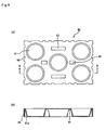
- Figs. 7 (a) and 8 (a) are plan views that schematically show one example of another packaging material in accordance with the present invention
- Figs. 7(b) and 8(b) are cross-sectional views taken along line A-A of the packaging materials Figs. 7(a) and 8(a) , respectively.
- the packaging material 70 is a packaging material formed by molding a plastic sheet, and has a structure in which bottomed holes 71, each used for installing the end face neighborhood of a honeycomb structured body, are formed on its upper face and a plurality of grooves (installation-face reinforcing portions) 72 are formed on a part of the area where no bottomed hole 71 is formed.
- the grooves 72 are formed in such a manner that when each of them crosses another groove, the two grooves are made orthogonal to each other.
- a peripheral side face 74 formed by bending a plastic sheet downward, is formed on the peripheral portion of the packing member 70.
- the embodiment of the packaging material 70 shown in Fig. 7 is the same as that of the packaging material 50 shown in Fig. 5 , except that no grooves (side-face reinforcing portions) are formed on the peripheral side face 74.
- the use of the packaging material 70 also prevents displacement and bending of the packaging material at the time when the honeycomb structured body, packaged and housed in the box member, is transported, or the like, and consequently can prevent the honeycomb structured body from being damaged. In this manner, even in the case where the reinforcing portions are formed only on the upper face of the plastic sheet, the same effects as those of the present invention can be obtained.
- the packaging material 80 is a packaging material formed by molding a plastic sheet, and has a structure in which bottomed holes 81, each used for installing the end face neighborhood of an object to be packaged (honeycomb structured body), are formed on its upper face and a plurality of grooves (installation-face reinforcing portions) 83 are formed on a part of an area where no bottomed hole 81 is formed.
- a peripheral side face 84 formed by bending a plastic sheet downward, is formed on the peripheral portion of the packing member 80, and a plurality of grooves (side-face reinforcing portions) 85, which serve as reinforcing portions, are further formed on the peripheral side face 84.
- the shape of the packaging material 80 shown in Fig. 8 is the same as that of the packaging material 50 shown in Fig. 5 , except that in place of the grooves, concave portions 83 are formed on the upper face thereof. In the same manner as the grooves 52 formed in the packaging material 50, the concave portions 83 have a function for preventing the packaging material 80 from being bent.
- the use of the packaging material 80 also prevents displacement and bending of the packaging material at the time when the honeycomb structured body, packaged and housed in the box member, is transported, or the like, and consequently can prevent the honeycomb structured body from being, for example, damaged.
- the grooves and the concave portions serving as the installation face reinforcing portions which are formed in an area that bears no bottomed holes, are allowed to have virtually the same functions and structures; however in the present specification, those having the end portion extending to the side face of each bottomed hole are referred to as groove, and those formed in a completely independent manner from each bottomed hole is referred to as the concave portion.
- both of the groove and the concave portion may be formed on each of the installation face and the peripheral side face of a signal packaging material.
- a packaging material which is not part of the invention, may be the embodiment as shown in Fig. 9 .
- Fig. 9 (a) is a plan view that schematically shows an example of a packaging material which is not part of the invention and
- Fig. 9(b) is a cross-sectional view taken along line A-A of the packaging material of Fig. 9(a) .
- bottomed holes 91 used for installing the end face neighborhood of an object to be packaged are formed on its upper face and a plurality of concave portions (installation-face reinforcing portions) 93 serving as reinforcing portions are formed on a part of the area where no bottomed holes 91 are formed.
- a peripheral side face 94, formed by bending a plastic sheet downward, is formed on the peripheral portion of the packing member 90, and a plurality of grooves 95 serving as reinforcing portions are formed on the peripheral side face 94.
- Each bottomed hole 91 is formed in such a manner that the opening diameter is made greater than the diameter of the end face of a honeycomb structured body, and a side face 91a thereof is formed in a tapered shape with the diameter decreasing toward the bottom face.
- the embodiment of the packaging material 90 shown in Fig. 9 is the same as that of the packaging material 80 shown in Fig. 8 , except that no raised portion is formed on the bottom face of each bottomed hole 91.
- the packaging material of the present invention even in the case where no raised portion is formed in each bottomed hole, as long as concave portions are formed on both of the area of the upper face where no bottomed holes are formed and the peripheral side face, the above-mentioned effects, that is, the effects of preventing the occurrence of displacement and bending in the packaging material, for example, at the time when the honeycomb structured body, packaged and housed in the box member, is transported, and preventing the honeycomb structured body from being damaged, and the like, can be obtained.
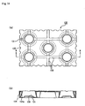
- the packaging material in accordance with the present invention may be an embodiment as shown in Fig. 13 .
- Fig. 13 (a) is a plan view that schematically shows another example of the packaging material in accordance with the present invention
- Fig. 13 (b) is a cross-sectional view taken along line A-A of the packaging material of Fig. 13(a) .
- a packaging material 120 shown in Fig. 13 is provided with bottomed holes 121 that serve as installation portions for honeycomb structural bodies.
- Each of the bottomed holes 121 is formed in such a manner that the diameter of its opening portion is made larger than the diameter of the end face of the honeycomb structured body, and the side face 121a thereof is formed into a tapered shape with the diameter decreasing toward the bottom face, and a raised bottom portion (installation portion) 126, which holds the end face of the honeycomb structured body, is formed on the bottom face.
- the raised bottom portion 126 is formed with such a size that only one portion of the end face of the honeycomb structured body is supported.
- the raised bottom portion 126 has a shape of a truncated cone shape in which a concave portion 126b is formed in the center thereof.
- the installation portion having this structure since the contact area between the end face of the honeycomb structured body and the installation portion is made smaller, the occurrence of damage and the like in the honeycomb structured body tends to be reduced.
- the shape of the packaging material 120 shown in Fig. 13 is the same as that of the packaging material 50 shown in Fig. 5 , except that the shape of the raised bottom portion 126 is different; therefore, the description thereof is omitted.
- the packaging material in accordance with the present invention may be the embodiment as shown in Fig. 14 .
- Fig. 14 (a) is a plan view that schematically shows another example of the packaging material in accordance with the present invention
- Fig. 14(b) is a cross-sectional view taken along line A-A of the packaging material of Fig. 14(a) .
- Each of bottomed holes 131 is formed in such a manner that the diameter of its opening portion is made larger than the diameter of the end face of the honeycomb structured body, and a side face 131a thereof is formed into a tapered shape with the diameter decreasing toward the bottom face, and a raised bottom portion (installation portion) 136, which holds the end face of the honeycomb structured body, is formed on the bottom face.
- the raised bottom portion 136 is formed in a size that supports only a part of the end face of the honeycomb structured body.
- the installation portion having this structure since the contact area between the end face of the honeycomb structured body and the installation portion is made smaller, the occurrence of damages and the like to the honeycomb structured body tends to be reduced.
- the shape of the packaging material 130 shown in Fig. 14 is the same as that of the packaging material 50 shown in Fig. 5 , except that the shape of the bottomed hole 131 is different; therefore, the description thereof is omitted.
- the reinforcing portion is desirably formed by installing grooves and/or concave portions in the plate member.
- the structure in which the grooves and/or concave portions that function as reinforcing portions are formed on the plate member in this manner makes the manufacturing process easier and is economically advantageous, in comparison with the structure of a packaging material (for example, see Fig. 3 , etc.) in which a reinforcing portion, made of a material different from the plate member, is manufactured and secured thereto.
- the installation portion is constructed by forming a bottomed hole in the plate member. It then becomes possible tomorepositively package the packaged honeycomb structured body.
- the installation area for an object to be packaged in the bottomed hole is preferably made smaller than the opening area of the bottomed hole.
- the bottomed hole is formed into this shape, the occurrence of damage, such as breakage and cracks , on the end portion and side face of the honeycomb structured body tends to be reduced.
- the bottomed hole is preferably formed into such a shape that, when an object to be packaged is installed, a gap is formed between the bottomed hole and the object to be packaged.
- the bottomed hole is formed into this shape, the occurrence of damages, such as breakage and cracks, on the end portion and side face of the honeycomb structured body tends to be reduced.
- the bottomed hole used for housing the end face neighborhood of the honeycomb structured body is not necessarily formed into a tapered shape on its side face as shown in Fig. 5 and the like, and the opening and the bottom face may have the same diameter.
- the packaging material is made of a plate member, and a plastic sheet may be used as the plate member.
- a plastic sheet may be used as the plate member.
- the plastic material include polypropylene, polyethylene, polyethylene terephthalate and the like.
- the material for the plate member is not limited to plastics, and the examples thereof include cardboard, styrofoam, and the like.
- the packaging material is constituted by a plastic sheet in its entire portion including reinforcing portions
- it can be manufactured by using a conventionally known molding method for a plastic material, such as a vacuum molding method and an injection molding method, and while in the case where the reinforcing portions are formed by using another material such as metal and wood, a method in which the base portion (portions other than the reinforcing portions) of the packaging material is manufactured by the above-mentioned method, and the reinforcing portions are secured thereto by using a bonding agent or the like, may be used.
- This packaging material comprises a plate member, which packages an object to be packaged by sandwiching the object, and the plate member is provided with an installation portion for the obj ect to be packaged comprising a bottomed hole, and the installation area for the object to be packaged in the bottomed hole is made smaller than the opening area of the bottomed hole.
- this packaging material examples thereof include a shape in which no reinforcing portions are formed, and an installation portion that is the same as in the packaging materials shown in Figs. 5 , 7 to 9 , 13 and 14 is formed, and the like. With this shape, the end face neighborhood of the object to be packaged can be easily inserted into the bottomed hole so that the object to be packaged can be easily packaged.
- This packaging material is made of a plate member, and specific examples of the plate member include those plate members similar to the plate members constituting the packaging materials in accordance with the present invention. Moreover, this packaging material can be manufactured by using a conventionally known molding method for a plastic material, such as a vacuum molding method and an injection molding method, and the like.
- This packaging material comprises a plate member, which packages an object to be packaged by sandwiching the object, and the plate member is provided with installation portions for objects to be packaged comprising a bottomed hole, and the bottomed hole has such a shape that, when an object to be packaged is placed therein, a gap is formed between the bottomed hole and the object to be packaged.
- this packaging naterial example thereof include a shape in which no reinforcing portions are formed, and an installation portion that is the same as those packaging materials shown in Figs. 5 , 7 , 8 , 13 and 14 is formed, and the like.
- the end face particularly, corner portions of the end face
- damage is far less likely to happen.
- This packaging material is made of a plate member, and specific examples of the plate member include those plate members similar to the plate member constituting the packaging materials in accordance with the present invention. Moreover, this packaging material can be manufactured by using a conventionally known molding method for a plastic material, such as a vacuummoldingmethod and an inj ectionmolding method, and the like.
- This packaging material packages an object to be packaged by sandwiching the object, and comprises:
- Fig. 10 (a) is a vertical cross-sectional view that shows this packaging material
- Fig. 10 (b) is a cross-sectional view taken along line A-A of Fig. 10(a)
- Fig. 10(c) is a cross-sectional view taken along line B-B of Fig. 10(a)
- Fig. 10(d) is a developed view of the packaging material shown in Fig. 10(a)
- Fig. 10 (a) is a vertical cross-sectional view taken along line C-C of each of Fig. 10(b) and Fig. 10(c)
- ⁇ to ⁇ in Fig. 10(a) respectively correspond to ⁇ to ⁇ in those of each Figs. 10(b) to 10(d) .
- a packaging material 100 is a packaging material formed by processing a sheet of cardboard, and comprises an installation member 102 in which an installation portion 101 for placing the end face neighborhood of the end faces of an obj ect to be packaged (honeycomb structured body) is formed, a holding member 104 in which a through hole 103 is formed, and a protective member 105, and the above members are configured into an integral unit through connecting portions 107A and 107B.
- a notched portion 106 is formed on the periphery of the installation unit 101 so that the entire bottom face of the object to be packaged is prevented from coming into contact with the protective member and the installation member.
- the notched portion 106 may be formed on demand.
- a cardboard having a large area as shown in Fig. 10 (d) is used, and first, two side portions are bent downward along lines extending from starting points ⁇ and ⁇ , and further bent inward along lines extending from starting points ⁇ and ⁇ so that the installation member 102 and the protective member 105 are superposed one on the other. Lastly, the two side portions respectively sandwiching the lines extending from the starting points ⁇ and ⁇ , as well as the lines extending from the starting points ⁇ and ⁇ , are folded inward so as to make a 90° angle each so that the installation member 102 and the protective member 105 are completely overlapped with each other.
- the installation member 102 is arranged to be placed on the protective member 105.
- a packaging material 100 which has a rectangular parallelepiped shape in the outer appearance and has a cross section shown in Fig. 1(a) , taken along line C-C of each of Figs. 10(b) and 10(c) , can be manufactured.
- the end portion of a honeycomb structured body (indicated by a dashed line in the Figure) is placed on the installation portion 101 of the installationmember 102, with the honeycomb structured body being allowed to penetrate the through hole 103 formed in the holding member 104; accordingly, the honeycomb structured body is held.
- the protective member 105 is formed, the strength of the packaging material can be improved. Therefore, no displacement or the like are caused in the honeycomb structured body, and thus the obj ect to be packaged can be positively held.
- the packaging material 100 has such a superior strength that it can prevent a packaging material from being bent at the time of transporting the packaging material housed in a box member, and consequently, no damage and the like is caused to the honeycomb structured body.
- peripheral side faces 107A and 107B are formed between the installation member 102 and the holding member 104, and between the holding member 104 and the protective member 105, respectively.
- the formation of the peripheral side faces 107A and 107B makes it possible to increase the contact area between the packaging material 100 and the inner face of a box member when the packaging material 100 is housed in the box member, and consequently the risk of displacement or bending of the packaging material 100 inside the box member is reduced, thereby further preventing the honeycomb structured body from being damaged.
- concave portions and through holes may be formed on the peripheral side faces 107A and 107B, if necessary. These arrangements contribute to weight saving and an easy bending upon manufacturing.
- a concave portion is preferably formed on the side face 107B to achieve an easy fitting.
- This material for the packaging material is not limited to cardboard, and plastic materials, styrofoam, and the like may be used in the same manner as the packaging material in accordance with the present invention.
- the packaging material may be manufactured by processing, for example, a cardboard through a conventionally known method.
- This packaging material is used for packaging a pillar-shaped object to be packaged, comprises:
- Fig. 11 (a) is a vertical cross-sectional view that shows this packaging material
- Fig. 11 (b) is a horizontal cross-sectional view of the packaging material.
- Fig. 11 (a) is a vertical cross-sectional view taken along line B-B of Fig. 11(b)
- Fig. 11(b) is a horizontal cross-sectional view taken along line A-A of Fig. 11(a) .
- a packaging material 60 is a packaging material formed by processing a sheet of cardboard, and has a structure in which a bottom holding member 62A in which a bottomed hole 61A that houses an end face neighborhood of one of the end faces of the object to be packaged (honeycomb structured body) is formed, and an upper holding member 62B in which a bottomed hole 61B that houses the end face neighborhood of the other end face of the honeycomb structured body is formed are configured into an integral unit through an intermediate holding member 63.
- the bottomed hole 61A and the bottomed hole 61B are formed at such positions as to be overlapped with each other in the plan view.
- the through hole that allows the penetration of the honeycomb structured body is formed in the intermediate holding member 63 and the through hole is formed in such a position that the bottomed hole 61A and the bottomed hole 61B are overlapped with each other in the plan view.
- the end portions of a honeycomb structured body are respectively held by the bottomed hole 61A and the bottomed hole 61B, and by allowing the honeycomb structured body to penetrate the through hole formed in the intermediate holding member 63, the honeycomb structured body is further supported.
- the honeycomb structured body can be reliably supported without displacement and the like.
- the packaging material 60 has a structure in which the bottom holding member 62A, the upper holding member 62B and the intermediate holding member 63 are configured into an integral unit, therefore has such a superior strength that it can prevent a packaging material from being bent at the time of transporting the packaging material housed in a box member, and consequently, no damage and the like is caused to the honeycomb structured body.
- peripheral side faces 64A and 64B are respectively formed on the bottom holding member at the side opposite to the side that is integral with the intermediate holding member, and on the upper holding member at the side opposite to the side that is integral with the intermediate holding member.
- the material for this packaging material is not limited to cardboard, and plastic materials, styrofoam, and the like may be used in the same manner as the packaging material in accordance with present invention.
- This packaging material may be manufactured by processing, for example, a cardboard through a conventionally known method.
- Methods of transporting a honeycomb structured body in accordance with the present invention are methods of transporting a honeycomb structured body using the packaging materials of the present invention, respectively, and since the transporting method has been explained above in the present specification, the specific explanation thereof is omitted.
- honeycomb structured body examples thereof include a filter used for capturing particulates in the exhaust gas, a honeycomb structured body used as a catalyst supporting carrier for converting the exhaust gas, and the like.
- Examples 1-32, 81, 82, text examples 1-16 and the comparative example 1 are not part of the invention.
- a packaging material having the same shape as the packaging material 10 of Fig. 1 was manufactured.
- a polypropylene sheet of 0.5 mm in thickness was used as a plate member, and each of reinforcing portions (installation face reinforcing units) 12 was formed by securing a plywood plate of 20 mm in width and 1 mm in thickness.
- each of the installation portions 11 had a size of 130 mm in the upper face diameter ⁇ 150 mm in the bottom face diameter
- the groove (side face reinforcing portion) 15 had a size of 20 mmin width ⁇ 5 mm in depth
- the external size was set to 560 mm in width ⁇ 380 mm in length ⁇ 50 mm in height.
- the polypropylene sheet was processed so that the surface roughness of the upper face of the installation portion 11 was set to 0.1 mm.
- a packaging material was manufactured in the same manner as Example 1, except that grooves 15 were not formed in the peripheral side face portion 14, and a plywood plate (Example 2) of 20 mm in width and 1 mm in thickness, or an aluminum plate (Example 3) of 20 mm in width and 0.5 mm in thickness was secured onto a position corresponding to each of the grooves as a side face reinforcing portion.
- a packaging material was manufactured in the same manner as Example 1, except that, in place of each of the grooves on the peripheral side face, a concave portion (see 45 in Fig. 4 ) having a size of 20 mm in width ⁇ 5 mm in depth ⁇ 30 mm in height was formed as a side face reinforcing portion.
- a packaging material was manufactured in the same manner as in the respective Examples 1 to 4, except that the reinforcing portion 12 was formed by using an aluminum plate of 2 mm in width and 0.5 mm in thickness in place of the plywood plate.
- a packaging material was manufactured in the same manner as in the respective Examples 1 to 4, except that the reinforcing portion 12 was formed not by securing a plywood plate, but by molding the polypropylene sheet.
- the reinforcing portion had a size of 20 mm in width ⁇ 5 mm in height.
- a packaging material was manufactured in the same manner as in the respective Examples 9 to 12, except that the shape of each installation face reinforcing portion was changed to a reinforcing portion 43 shown in Fig. 4 from a reinforcing portion 12 shown in Fig. 1 .
- the reinforcing portion had a size of 20 mm in width ⁇ 150 mm in length ⁇ 5 mm in height or 20 mm in width ⁇ 50 mm in length ⁇ 5 mm in height.
- a packaging material was manufactured in the same manner as in the respective Examples 1, 5, 9 and 13, except that no side face reinforcing portions were formed.
- a packaging material was manufactured in the same manner as in the respective Examples 1 to 4, except that no installation face reinforcing portions were formed.
- a packaging material having the same shape as the packaging material 110 of Fig. 12 was manufactured.
- a polypropylene sheet of 0.5 mm in thickness was used as a plate member, and each of reinforcing portions (installation face reinforcing units) 112 was formed by securing a plywood plate of 20 mm in width and 1 mm in thickness.
- each of the installation portions 111 had a size of 130 mm in the upper face outer diameter L 1 , 120 mm in the upper face inner diameter L 2 , 150 mm in the bottom face outer diameter M 1 and 100 mm in the bottom face inner diameter M 2
- each of grooves (side face reinforcing portions) 115 of the peripheral side face 114 had a size of 20 mm in width ⁇ 5 mm in depth, and the external size was set to 560 mm in width ⁇ 380 mm in depth ⁇ 50 mm in height.
- the polypropylene sheet was processed so that the surface roughness of the upper face of the installation portion 111 was set to 1 mm.
- a packaging material was manufactured in the same manner as Example 17, except that grooves 115 were not formed on the peripheral side face 114, and a plywood plate (Example 18) of 20 mm in width and 1 mm in thickness, or an aluminumplate (Example 19) of 20 mm in width and 0.5 mm in thickness was secured as a side face reinforcing portion onto a position corresponding to each of the grooves.
- a packaging material was manufactured in the same manner as Example 17, except that, in place of each of the grooves on the peripheral side face, a concave portion (see 45 in Fig. 4 ) having a size of 20 mm in width ⁇ 5 mm in depth ⁇ 30 mm in height was formed as a side face reinforcing portion.
- a packaging material was were manufactured in the same manner as in the respective Examples 17 to 20, except that the reinforcing portion 112 was formed by using an aluminum plate of 2 mm in width and 0.5 mm in thickness in place of the plywood plate.
- a packaging material was manufactured in the same manner as in the respective Examples 17 to 20, except that the reinforcing portion 112 was formed not by securing a plywood plate, but by molding the polypropylene sheet.
- the reinforcing portion had a size of 20 mm in width ⁇ 5 mm in height.
- a packaging material was manufactured in the same manner as in the respective Examples 17 to 20, except that the shape of each reinforcing portion to be formed on the same face as the face bearing the installation portion was changed to a reinforcing portion 43 shown in Fig. 4 from a reinforcing portion 112 shown in Fig. 12 .
- the reinforcing portion had a size of 20 mm in width ⁇ 150 mm in length ⁇ 5 mm in height or 20 mm in width ⁇ 50 mm in length ⁇ 5 mm in height.
- a packaging material was manufactured in the same manner as in the respective Examples 17, 21, 25 and 29, except that no side face reinforcing portions were formed.
- a packaging material was manufactured in the same manner as in the respective Examples 17 to 20, except that no installation face reinforcing portions were formed.
- a packaging material having the same shape as the packaging material 50 shown in Fig. 5 was manufactured.
- a polypropylene sheet of 0.5 mm in thickness was used as a plate member, and each of reinforcing portions (grooves) 52 had a size of 20 mm in width and 5 mm in depth.
- the bottomed hole 51 had a size of 155 mm in the opening diameter, 150 mm in the bottom face diameter and 130 mm in the upper face diameter of the raised bottom portion 56, and each groove (side-face reinforcing portion) 55 of the peripheral side face 54 had a size of 20 mm in width ⁇ 5 mm in depth and an external size of 560 mm in width ⁇ 380 mm in depth ⁇ 50 mm in height.
- the polypropylene sheet was processed so that the surface roughness of the upper face of the raised bottom portion 56 was set to 0.1 mm.
- a packaging material was manufactured in the same manner as Example 33, except that grooves 55 were not formed on the peripheral side face 54, and a plywood plate (Example 34) of 20 mm in width and 1 mm in thickness or an aluminum plate (Example 35) of 20 mm in width and 0.5 mm in thickness was secured onto a position corresponding to each of the grooves as a side face reinforcing portion.
- a packaging material was manufactured in the same manner as Example 33, except that, in place of each of the grooves on the peripheral side face, a concave portion (see 45 in Fig. 4 ) having a size of 20 mm in width ⁇ 5 mm in depth ⁇ 30 mm in height was formed as a side face reinforcing portion.
- a packaging material was manufactured in the same manner as in the respective Examples 33 to 36, except that grooves 52 were not formed, and a plywood plate of 2 mm in width and 1 mm in thickness was secured as an installation face reinforcing portion onto a position corresponding to each of the grooves.
- a packaging material was manufactured in the same manner as in the respective Examples 33 to 36, except that grooves 52 were not formed, and an aluminum plate of 2 mm in width and 0.5 mm in thickness was secured onto a position corresponding to each of the grooves as an installation face reinforcing portion.
- a packaging material was manufactured in the same manner as in the respective Examples 33 to 36, except that the shape of each installation face reinforcing portion was changed to a concave portion 83 shown in Fig. 8 from the groove 52 shown in Fig. 5 .
- the reinforcing portion had a size of 20 mm in width ⁇ 150 mm in length ⁇ 5 mm in depth or 20 mm in width ⁇ 50 mm in length ⁇ 5 mm in depth.
- a packaging material was manufactured in the same manner as in the respective Examples 33, 37, 41 and 45, except that no side face reinforcing portions were formed.
- a packaging material was manufactured in the same manner as in the respective Examples 33 to 36, except that no installation face reinforcing portions were formed.
- a packaging material having the same shape as the packaging material 120 of Fig. 13 was manufactured.
- a polypropylene sheet of 0.5 mm in thickness was used as a plate member, and each of grooves (installation face reinforcing units) 122 had a size of 20 mm in width and 5 mm in depth.
- the bottomed hole 121 had a size of 155 mm in the opening diameter and 150 mm in the bottom face diameter
- the raised bottom portion 126 had a size of 130 mm in outer diameter and 120 mm in inner diameter
- each groove (side-face reinforcing portion) 125 of the peripheral side face 124 had a size of 20 mm in width ⁇ 5 mm in depth and an external size of 560 mm in width ⁇ 380 mm in depth ⁇ 50 mm in height.
- the polypropylene sheet was processed so that the surface roughness of the upper face of the raised bottom portion 126 was set to 1 mm.
- a packaging material was manufactured in the same manner as Example 49, except that grooves 125 were not formed on the peripheral side face 124, and a plywood plate (Example 50) of 20 mm in width and 1 mm in thickness or an aluminum plate (Example 51) of 20 mm in width and 0.5 mm in thickness was secured onto a position corresponding to each of the grooves as a side face reinforcing portion.
- a packaging material was manufactured in the same manner as Example 49, except that, in place of each of the grooves on the peripheral side face, a concave portion (see 45 in Fig. 4 ) having a size of 20 mm in width ⁇ 5 mm in depth ⁇ 30 mm in height was formed as a side face reinforcing portion.
- a packaging material was manufactured in the same manner as in the respective Examples 49 to 52, except that grooves 122 were not formed, and a plywood plate of 2 mm in width and 1 mm in thickness was secured onto a position corresponding to each of the grooves as an installation face reinforcing portion.
- a packaging material was manufactured in the same manner as in the respective Examples 49 to 52, except that grooves 122 were not formed, and an aluminum plate of 2 mm in width and 0.5 mm in thickness was secured onto a position corresponding to each of the grooves as an installation face reinforcing portion.
- a packaging material was manufactured in the same manner as in the respective Examples 49 to 52, except that the shape of each installation face reinforcing portion was changed to a concave portion 83 shown in Fig. 8 from the groove 122 shown in Fig. 13 .
- the reinforcing portion had a size of 20 mm in width ⁇ 150 mm in length ⁇ 5 mm in height, or 20 mm in width ⁇ 50 mm in length ⁇ 5 mm in depth.
- a packaging material was manufactured in the same manner as in the respective Examples 49, 53, 57 and 61, except that no side face reinforcing portions were formed.
- a packaging material was manufactured in the same manner as in the respective Examples 49 to 52, except that no installation face reinforcing portions were formed.
- Apackagingmaterial having the same shape as the packaging material 130 of Fig. 14 was manufactured.
- a polypropylene sheet of 0.5 mm in thickness was used as a plate member, and each of grooves (installation face reinforcing units) 132 had a size of 20 mm in width and 5 mm in depth.
- the bottomed hole 131 had a size of 155 mm in the opening diameter and 165 mm in the bottom face diameter
- the raised bottom portion 136 had a size of 130 mm in outer diameter
- each groove (side-face reinforcing portion) 135 of the peripheral side face 134 had a size of 20 mmin width ⁇ 5 mm in depth and an external size of 560 mm in width ⁇ 380 mm in depth ⁇ 50 mm in height.
- the polypropylene sheet was processed so that the surface roughness of the upper face of the raised bottom portion 136 was set to 1 mm.
- a packaging material was manufactured in the same manner as Example 65, except that grooves 135 were not formed on the peripheral side face 134, and a plywood plate (Example 66) of 20 mm in width and 1 mm in thickness or an aluminum plate (Example 67) of 20 mm in width and 0.5 mm in thickness was secured onto a position corresponding to each of the grooves as a side face reinforcing portion.
- a packaging material was manufactured in the same manner as Example 65, except that, in place of each of the grooves on the peripheral side face, a concave portion (see 45 in Fig. 4 ) having a size of 20 mm in width ⁇ 5 mm in depth ⁇ 30 mm in height was formed as a side face reinforcing portion.
- a packaging material was manufactured in the same manner as in the respective Examples 65 to 68, except that grooves 132 were not formed, and a plywood plate of 2 mm in width and 1 mm in thickness was secured onto a position corresponding to each of the grooves as an installation face reinforcing portion.
- a packaging material was manufactured in the same manner as in the respective Examples 65 to 68, except that grooves 132 were not formed, and an aluminum plate of 2 mm in width and 0.5 mm in thickness was secured onto a position corresponding to each of the grooves as an installation face reinforcing portion.
- a packaging material was manufactured in the same manner as in the respective Examples 65 to 68, except that the shape of each installation face reinforcing portion was changed to a concave portion 83 shown in Fig. 8 from the groove 132 shown in Fig. 14 .
- the reinforcing portion had a size of 20 mm in width ⁇ 150 mm in length ⁇ 5 mm in depth, or 20 mm in width ⁇ 50 mm in length ⁇ 5 mm in depth.
- a packaging material was manufactured in the same manner as in the respective Examples 65, 69, 73 and 77, except that no side face reinforcing portions were formed.
- a packaging material was manufactured in the same manner as in the respective Examples 65 to 68, except that no installation face reinforcing portions were formed.
- a packaging material 60 having a shape shown in Fig. 11 was manufactured by processing a cardboard having a thickness of 5 mm.
- the packaging material 60 manufactured in the present example had an external size of 530 mm ⁇ 340 mm, and each of bottomed holes 61A and 61B had an opening diameter of 148 mm.
- a packaging material 100 having a shape shown in Fig. 10 was manufactured by processing a cardboard having a thickness of 5 mm.
- the packaging material 100 manufactured in the present example had an external size of 530 mm ⁇ 340 mm ⁇ 50 mm, and each of through holes 103 had an opening diameter of 148 mm.
Landscapes
- Engineering & Computer Science (AREA)
- Mechanical Engineering (AREA)
- Packages (AREA)
- Buffer Packaging (AREA)
- Packaging Frangible Articles (AREA)
- Supplying Of Containers To The Packaging Station (AREA)
- Container Filling Or Packaging Operations (AREA)
- Basic Packing Technique (AREA)
Claims (12)
- Verwendung eines Packmaterials (50) zum Verpacken eines zu verpackenden Wabenstrukturkörpers (20), wobei die untere Seite und die obere Seite des Wabenstrukturkörpers mit dem Packmaterial verpackt werden, wobei
das Packmaterial mit einem Einbauabschnitt für den zu verpackenden Wabenstrukturkörper und auch mit einem Einbauflächenverstärkungsabschnitt (52) versehen ist,
wobei der Einbauabschnitt so ausgebildet ist, dass ein Durchmesser eines oberen Flächenabschnitts des Einbauabschnitts kleiner hergestellt ist als ein Durchmesser einer Endfläche des Wabenstrukturkörpers,
wobei der Einbauabschnitt in einer Größe ausgebildet ist, die nur einen Teil einer Endfläche des Wabenstrukturkörpers abstützt, und
der Wabenstrukturkörper durch das Kontaktieren nur eines Teils der Endfläche des Wabenstrukturkörpers mit dem oberen Flächenabschnitt des Einbauabschnitts abgestützt wird, dadurch gekennzeichnet, dass
der Einbauabschnitt durch Ausbilden eines mit einem Unterteil versehenen Lochs (51) in dem Packmaterial ausgebildet wird,
ein erhöhter Unterteilabschnitt (56), der eine Endfläche des Wabenstrukturkörpers hält, auf einer Unterteilfläche des mit einem Unterteil versehenen Lochs ausgebildet ist, und
der erhöhte Unterteilabschnitt (56) in einer Größe ausgebildet ist, die nur einen Teil der Endfläche des Wabenstrukturkörpers abstützt. - Verwendung eines Packmaterials nach Anspruch 1, bei welcher
der Einbauflächenverstärkungsabschnitt (52) dadurch ausgebildet ist, dass ein Nutenabschnitt und/oder ein konkaver Abschnitt in dem Packmaterial ausgebildet ist. - Verwendung eines Packmaterials nach Anspruch 1, bei der
die Einbaufläche für den zu verpackenden Wabenstrukturkörper (20) in dem mit einem Unterteil versehenen Loch (51) kleiner ist als die Öffnungsfläche des mit einem Unterteil versehenen Lochs. - Verwendung eines Packmaterials nach Anspruch 1, bei der
das mit einem Unterteil versehene Loch (51) eine solche Form aufweist, dass, wenn ein zu verpackender Wabenstrukturkörper (20) darin angeordnet wird, eine Lücke zwischen dem mit einem Unterteil versehenen Loch und dem zu verpackenden Wabenstrukturkörper gebildet wird. - Verwendung eines Packmaterials nach einem der vorherigen Ansprüche, bei der
ein Material für das Packmaterial (50) Kunststoff ist. - Verwendung eines Packmaterials nach einem der vorherigen Ansprüche, bei der
ein Material für den Einbauflächenverstärkungsabschnitt (52) Kunststoff, Holz, Metall, Pappe oder Styropor ist. - Verfahren zum Transportieren eines Wabenstrukturkörpers mit dem Aufbewahren eines Wabenstrukturkörpers (20), der mit einem Packmaterial (50) verpackt ist, in einem Kastenelement (21), und dem anschließenden Transportieren des Kastenelements (21), wobei
das Packmaterial (50) einen zu verpackenden Wabenstrukturkörper (20) verpackt, wobei die untere Seite und die obere Seite des Wabenstrukturkörpers mit dem Packmaterial verpackt sind, und
das Packmaterial mit einem Einbauabschnitt für den zu verpackenden Wabenstrukturkörper versehen ist, und es auch mit einem Einbauflächenverstärkungsabschnitt (52) versehen ist, wobei
der Einbauabschnitt so ausgebildet ist, dass ein Durchmesser eines oberen Flächenabschnitts des Einbauabschnitts kleiner hergestellt ist als ein Durchmesser einer Endfläche des Wabenstrukturkörpers,
der Einbauabschnitt in einer Größe ausgebildet ist, die nur einen Teil einer Endfläche des Wabenstrukturkörpers abstützt, und
der Wabenstrukturkörper dadurch abgestützt wird, dass nur ein Teil der Endfläche des Wabenstrukturkörpers mit dem oberen Flächenabschnitt des Einbauabschnitts kontaktiert, dadurch gekennzeichnet, dass
der Einbauabschnitt dadurch ausgebildet ist, dass ein mit einem Unterteil versehenes Loch (51) in dem Packmaterial ausgebildet ist,
ein erhöhter Unterteilabschnitt (56), der eine Endfläche des Wabenstrukturkörpers hält, auf einer Unterteilfläche des mit einem Unterteil versehenen Lochs ausgebildet ist, und
der erhöhte Unterteilabschnitt (56) in einer Größe ausgebildet ist, die nur einen Teil der Endfläche des Wabenstrukturkörpers abstützt. - Verfahren zum Transportieren eines Wabenstrukturkörpers nach Anspruch 7, bei dem
der Einbauflächenverstärkungsabschnitt (52) durch das Ausbilden eines Nutabschnitts und/oder eines konkaven Abschnitts in dem Packmaterial ausgebildet ist. - Verfahren zum Transportieren eines Wabenstrukturkörpers nach Anspruch 7, bei dem
die Einbaufläche für den zu verpackenden Wabenstrukturkörper (20) in dem mit einem Unterteil versehenen Loch (51) kleiner ist als die Öffnungsfläche des mit einem Unterteil versehenen Lochs. - Verfahren zum Transportieren eines Wabenstrukturkörpers nach Anspruch 7, bei dem
das mit einem Unterteil versehene Loch (51) eine solche Form aufweist, dass, wenn ein zu verpackender Wabenstrukturkörper (20) darin angeordnet ist, eine Lücke zwischen dem mit einem Unterteil versehenen Loch und dem zu verpackenden Wabenstrukturkörper gebildet wird. - Verfahren zum Transportieren eines Wabenstrukturkörpers nach einem der Ansprüche 7 bis 10, bei dem
ein Material für das Packmaterial (50) Kunststoff ist. - Verfahren zum Transportieren eines Wabenstrukturkörpers nach einem der Ansprüche 7 bis 11, bei dem
ein Material für den Einbauflächenverstärkungsabschnitt (52) Kunststoff, Holz, Metall, Pappe oder Styropor ist.
Applications Claiming Priority (2)
| Application Number | Priority Date | Filing Date | Title |
|---|---|---|---|
| JP2005165758 | 2005-06-06 | ||
| PCT/JP2006/303884 WO2006132011A1 (ja) | 2005-06-06 | 2006-03-01 | 梱包材及びハニカム構造体の輸送方法 |
Publications (3)
| Publication Number | Publication Date |
|---|---|
| EP1752390A1 EP1752390A1 (de) | 2007-02-14 |
| EP1752390A4 EP1752390A4 (de) | 2007-07-04 |
| EP1752390B1 true EP1752390B1 (de) | 2011-09-28 |
Family
ID=37498220
Family Applications (1)
| Application Number | Title | Priority Date | Filing Date |
|---|---|---|---|
| EP06715001A Expired - Lifetime EP1752390B1 (de) | 2005-06-06 | 2006-03-01 | Verwendung eines verpackungsmaterials und verfahren für den transport eines wabenförmig strukturierten körpers |
Country Status (5)
| Country | Link |
|---|---|
| US (1) | US8047377B2 (de) |
| EP (1) | EP1752390B1 (de) |
| JP (1) | JP4854664B2 (de) |
| AT (1) | ATE526252T1 (de) |
| WO (1) | WO2006132011A1 (de) |
Families Citing this family (51)
| Publication number | Priority date | Publication date | Assignee | Title |
|---|---|---|---|---|
| DE60033977T2 (de) * | 1999-09-29 | 2007-12-20 | Ibiden Co., Ltd., Ogaki | Wabenförmiger Filter und Anordnung von keramischen Filtern |
| JPWO2003067041A1 (ja) | 2002-02-05 | 2005-06-02 | イビデン株式会社 | 排気ガス浄化用ハニカムフィルタ、接着剤、塗布材、及び、排気ガス浄化用ハニカムフィルタの製造方法 |
| ATE376880T1 (de) | 2002-03-22 | 2007-11-15 | Ibiden Co Ltd | Herstellungsverfahren eines wabenfilters zur reinigung von abgas |
| CN100371562C (zh) | 2002-04-10 | 2008-02-27 | 揖斐电株式会社 | 废气净化用蜂窝状过滤器 |
| EP1500799B1 (de) * | 2002-04-11 | 2007-10-24 | Ibiden Co., Ltd. | Wabenfilter zur reinigung von abgas |
| WO2005026074A1 (ja) * | 2003-09-12 | 2005-03-24 | Ibiden Co., Ltd. | セラミック焼結体およびセラミックフィルタ |
| JP4849891B2 (ja) * | 2003-11-05 | 2012-01-11 | イビデン株式会社 | ハニカム構造体の製造方法 |
| JPWO2005108328A1 (ja) * | 2004-05-06 | 2008-03-21 | イビデン株式会社 | ハニカム構造体及びその製造方法 |
| EP1930058A3 (de) * | 2004-05-18 | 2008-07-30 | Ibiden Co., Ltd. | Wabenstrukturkörper und Abgasreinigungsvorrichtung |
| WO2006035822A1 (ja) * | 2004-09-30 | 2006-04-06 | Ibiden Co., Ltd. | ハニカム構造体 |
| DE602005015610D1 (de) * | 2004-10-12 | 2009-09-03 | Ibiden Co Ltd | Keramische wabenstruktur |
| WO2006082938A1 (ja) * | 2005-02-04 | 2006-08-10 | Ibiden Co., Ltd. | セラミックハニカム構造体およびその製造方法 |
| JP2006223983A (ja) * | 2005-02-17 | 2006-08-31 | Ibiden Co Ltd | ハニカム構造体 |
| JP4870559B2 (ja) | 2005-03-28 | 2012-02-08 | イビデン株式会社 | ハニカム構造体 |
| JP4937116B2 (ja) * | 2005-04-28 | 2012-05-23 | イビデン株式会社 | ハニカム構造体 |
| JP4854664B2 (ja) * | 2005-06-06 | 2012-01-18 | イビデン株式会社 | ハニカム構造体の輸送方法 |
| CN1954137B (zh) * | 2005-07-21 | 2011-12-21 | 揖斐电株式会社 | 蜂窝结构体以及废气净化装置 |
| JPWO2007058006A1 (ja) * | 2005-11-18 | 2009-04-30 | イビデン株式会社 | ハニカム構造体 |
| KR100882401B1 (ko) | 2005-11-18 | 2009-02-05 | 이비덴 가부시키가이샤 | 벌집형 구조체 |
| WO2007086143A1 (ja) * | 2006-01-30 | 2007-08-02 | Ibiden Co., Ltd. | ハニカム構造体の検査方法、及び、ハニカム構造体の製造方法 |
| US20070193912A1 (en) * | 2006-02-17 | 2007-08-23 | Ngk Insulators, Ltd. | Package |
| WO2007094075A1 (ja) | 2006-02-17 | 2007-08-23 | Ibiden Co., Ltd. | 乾燥用治具組立装置、乾燥用治具分解装置、乾燥用治具循環装置、セラミック成形体の乾燥方法、及び、ハニカム構造体の製造方法 |
| WO2007096986A1 (ja) | 2006-02-24 | 2007-08-30 | Ibiden Co., Ltd. | 端面加熱装置、ハニカム集合体の端面乾燥方法、及び、ハニカム構造体の製造方法 |
| WO2007097000A1 (ja) * | 2006-02-24 | 2007-08-30 | Ibiden Co., Ltd. | ハニカム成形体用封口装置、封止材ペーストの充填方法、及び、ハニカム構造体の製造方法 |
| DE602006002244D1 (de) * | 2006-02-28 | 2008-09-25 | Ibiden Co Ltd | Trageelement für Trocknung, Trocknungsverfahren eines Presslings mit Wabenstruktur, und Verfahren zur Herstellung eines Wabenkörpers. |
| WO2007122680A1 (ja) * | 2006-04-13 | 2007-11-01 | Ibiden Co., Ltd. | 押出成形機、押出成形方法及びハニカム構造体の製造方法 |
| WO2007122715A1 (ja) * | 2006-04-20 | 2007-11-01 | Ibiden Co., Ltd. | ハニカム焼成体の検査方法、及び、ハニカム構造体の製造方法 |
| WO2007132530A1 (ja) | 2006-05-17 | 2007-11-22 | Ibiden Co., Ltd. | ハニカム成形体用端面処理装置、ハニカム成形体の封止方法、及び、ハニカム構造体の製造方法 |
| EP1864774A1 (de) * | 2006-06-05 | 2007-12-12 | Ibiden Co., Ltd. | Verfahren und Vorrichtung zum Schneiden von einer Wabenstruktur |
| JP2008037469A (ja) | 2006-08-08 | 2008-02-21 | Ngk Insulators Ltd | 脆性柱状体用トレー |
| WO2008047404A1 (fr) * | 2006-10-16 | 2008-04-24 | Ibiden Co., Ltd. | Support de montage pour structure alvéolaire et dispositif d'inspection pour structure alvéolaire |
| US7677405B2 (en) * | 2006-11-21 | 2010-03-16 | Rehrig Pacific Company | Crate for containers |
| ATE532760T1 (de) * | 2007-03-29 | 2011-11-15 | Ibiden Co Ltd | Wabenstruktur und zugehöriges herstellungsverfahren |
| WO2008149435A1 (ja) * | 2007-06-06 | 2008-12-11 | Ibiden Co., Ltd. | 焼成用治具及びハニカム構造体の製造方法 |
| WO2008155856A1 (ja) * | 2007-06-21 | 2008-12-24 | Ibiden Co., Ltd. | ハニカム構造体、及び、ハニカム構造体の製造方法 |
| JP5180835B2 (ja) * | 2007-10-31 | 2013-04-10 | イビデン株式会社 | ハニカム構造体用梱包体、及び、ハニカム構造体の輸送方法 |
| WO2009066388A1 (ja) * | 2007-11-21 | 2009-05-28 | Ibiden Co., Ltd. | ハニカム構造体及びハニカム構造体の製造方法 |
| US20100276328A1 (en) | 2007-12-28 | 2010-11-04 | Soremartec S.A. | A method of packaging a product and corresponding package |
| WO2009101682A1 (ja) * | 2008-02-13 | 2009-08-20 | Ibiden Co., Ltd. | ハニカム構造体、排ガス浄化装置、及び、ハニカム構造体の製造方法 |
| WO2009101683A1 (ja) | 2008-02-13 | 2009-08-20 | Ibiden Co., Ltd. | ハニカム構造体の製造方法 |
| WO2009107230A1 (ja) * | 2008-02-29 | 2009-09-03 | イビデン株式会社 | ハニカム構造体用シール材、ハニカム構造体、及び、ハニカム構造体の製造方法 |
| WO2009118813A1 (ja) * | 2008-03-24 | 2009-10-01 | イビデン株式会社 | ハニカム構造体及びハニカム構造体の製造方法 |
| WO2009118814A1 (ja) * | 2008-03-24 | 2009-10-01 | イビデン株式会社 | ハニカムフィルタ |
| WO2009118862A1 (ja) * | 2008-03-27 | 2009-10-01 | イビデン株式会社 | ハニカム構造体の製造方法 |
| GB2529431A (en) * | 2014-08-19 | 2016-02-24 | Kraft Foods R & D Inc | Packaging and a method of manufacture |
| EP3251963A1 (de) * | 2016-06-02 | 2017-12-06 | ALKO Oy | Transportbehälter |
| US10894653B2 (en) * | 2018-12-10 | 2021-01-19 | Bsh Home Appliances Corporation | Extractor hood packing system |
| DE202020107614U1 (de) * | 2020-12-30 | 2021-01-27 | Tran & Tran Holding Gmbh | Seifenbehälter |
| JPWO2023127332A1 (de) * | 2021-12-28 | 2023-07-06 | ||
| US20240156147A1 (en) | 2022-11-15 | 2024-05-16 | Clear IP Corporation | Pre-roll filling system |
| US20240367086A1 (en) * | 2023-05-02 | 2024-11-07 | Pure Illusion, Inc. | Load redistribution packaging structure |
Family Cites Families (101)
| Publication number | Priority date | Publication date | Assignee | Title |
|---|---|---|---|---|
| GB102744A (en) * | 1916-01-03 | 1917-01-03 | Frederick John Shirley | Improvements in or relating to Boxes made from Cardboard or other Blanks. |
| IT1037841B (it) * | 1975-05-05 | 1979-11-20 | Anic Spa | Metodo per l imballaggio di supporti di filo continuo |
| DE2547822A1 (de) * | 1975-10-25 | 1977-04-28 | Riesselmann & Sohn | Verpackungselement fuer garnspulen |
| JPS5910284U (ja) * | 1982-07-12 | 1984-01-23 | 積水化成品工業株式会社 | 果実用の包装容器 |
| JPS59112778U (ja) * | 1983-01-18 | 1984-07-30 | 積水化成品工業株式会社 | 果物包装用トレイ |
| JPH0327938Y2 (de) * | 1986-04-25 | 1991-06-17 | ||
| DE8809724U1 (de) * | 1988-07-30 | 1988-09-29 | Wellpappenwerk Bruchsal GmbH & Co, 76646 Bruchsal | Tray für Palettenaufbau |
| JPH0644859Y2 (ja) * | 1992-03-12 | 1994-11-16 | 篤志 古江 | 箱内の収容物保護部材 |
| US5830548A (en) * | 1992-08-11 | 1998-11-03 | E. Khashoggi Industries, Llc | Articles of manufacture and methods for manufacturing laminate structures including inorganically filled sheets |
| US5914187A (en) | 1996-01-12 | 1999-06-22 | Ibiden Co., Ltd. | Ceramic structural body |
| JP3448435B2 (ja) * | 1996-07-01 | 2003-09-22 | 東洋アルミホイルプロダクツ株式会社 | 紙容器及び紙容器の成形方法 |
| DE60033977T2 (de) | 1999-09-29 | 2007-12-20 | Ibiden Co., Ltd., Ogaki | Wabenförmiger Filter und Anordnung von keramischen Filtern |
| US6588595B2 (en) * | 2000-09-15 | 2003-07-08 | Maxtor Corporation | Anti-motor fret package for multiple disk drives |
| US20040161596A1 (en) | 2001-05-31 | 2004-08-19 | Noriyuki Taoka | Porous ceramic sintered body and method of producing the same, and diesel particulate filter |
| JP2003112771A (ja) * | 2001-10-02 | 2003-04-18 | Ngk Insulators Ltd | 包装体 |
| EP1479882B2 (de) | 2002-02-05 | 2012-08-22 | Ibiden Co., Ltd. | Wabenfilter für abgasentgiftung |
| JPWO2003067041A1 (ja) | 2002-02-05 | 2005-06-02 | イビデン株式会社 | 排気ガス浄化用ハニカムフィルタ、接着剤、塗布材、及び、排気ガス浄化用ハニカムフィルタの製造方法 |
| US7427308B2 (en) | 2002-03-04 | 2008-09-23 | Ibiden Co., Ltd. | Honeycomb filter for exhaust gas decontamination and exhaust gas decontamination apparatus |
| DE60321831D1 (de) | 2002-03-15 | 2008-08-07 | Ibiden Co Ltd | Keramikfilter zur Abgasreinigung |
| ATE376880T1 (de) | 2002-03-22 | 2007-11-15 | Ibiden Co Ltd | Herstellungsverfahren eines wabenfilters zur reinigung von abgas |
| WO2003084640A1 (en) | 2002-04-09 | 2003-10-16 | Ibiden Co., Ltd. | Honeycomb filter for clarification of exhaust gas |
| CN100371562C (zh) | 2002-04-10 | 2008-02-27 | 揖斐电株式会社 | 废气净化用蜂窝状过滤器 |
| EP1500799B1 (de) | 2002-04-11 | 2007-10-24 | Ibiden Co., Ltd. | Wabenfilter zur reinigung von abgas |
| JP2004042964A (ja) * | 2002-07-12 | 2004-02-12 | Ngk Insulators Ltd | ハニカム状構造体用梱包容器及びハニカム状構造体の輸送方法 |
| ATE481151T1 (de) | 2003-02-28 | 2010-10-15 | Ibiden Co Ltd | Keramische wabenstruktur |
| CN100386505C (zh) | 2003-05-06 | 2008-05-07 | 揖斐电株式会社 | 蜂巢式结构体 |
| WO2005026074A1 (ja) | 2003-09-12 | 2005-03-24 | Ibiden Co., Ltd. | セラミック焼結体およびセラミックフィルタ |
| JP4849891B2 (ja) | 2003-11-05 | 2012-01-11 | イビデン株式会社 | ハニカム構造体の製造方法 |
| EP1790623B1 (de) | 2003-11-12 | 2009-05-13 | Ibiden Co., Ltd. | Verfahren zur Herstellung der Keramikstruktur |
| US7387829B2 (en) | 2004-01-13 | 2008-06-17 | Ibiden Co., Ltd. | Honeycomb structure, porous body, pore forming material for the porous body, and methods for manufacturing the pore forming material, the porous body and the honeycomb structure |
| WO2005099865A1 (ja) | 2004-04-05 | 2005-10-27 | Ibiden Co., Ltd. | ハニカム構造体、ハニカム構造体の製造方法及び排気ガス浄化装置 |
| JPWO2005108328A1 (ja) | 2004-05-06 | 2008-03-21 | イビデン株式会社 | ハニカム構造体及びその製造方法 |
| EP1930058A3 (de) | 2004-05-18 | 2008-07-30 | Ibiden Co., Ltd. | Wabenstrukturkörper und Abgasreinigungsvorrichtung |
| WO2006003736A1 (ja) | 2004-07-01 | 2006-01-12 | Ibiden Co., Ltd. | セラミック焼成用治具及び多孔質セラミック体の製造方法 |
| JPWO2006013651A1 (ja) | 2004-08-04 | 2008-05-01 | イビデン株式会社 | 焼成炉及びこれを用いた多孔質セラミック部材の製造方法 |
| EP1818639A4 (de) | 2004-08-04 | 2007-08-29 | Ibiden Co Ltd | Brennofen und verfahren zur herstellung eines gebrannten porösen keramikartikels unter verwendung des brennofens |
| KR100842595B1 (ko) | 2004-08-04 | 2008-07-01 | 이비덴 가부시키가이샤 | 연속 소성로 및 이것을 이용한 다공질 세라믹 부재의 제조방법 |
| EP1666826A4 (de) | 2004-08-06 | 2008-04-09 | Ibiden Co Ltd | Sinterofen und verfahren zur herstellung eines gesinterten körpers aus poröser keramik unter verwendung dieses ofens |
| EP1657511B1 (de) | 2004-08-10 | 2007-11-28 | Ibiden Co., Ltd. | Brennofen und verfahren zur herstellung von keramischen teilen mit diesem brennofen |
| EP1677063A4 (de) | 2004-08-25 | 2007-05-30 | Ibiden Co Ltd | KILN und Herstellungsverfahren eines porösen aus Keramik gebackenen Produktes unter Verwendung des KILN |
| EP1795261A4 (de) | 2004-09-30 | 2009-07-08 | Ibiden Co Ltd | Wabenstruktur |
| WO2006035822A1 (ja) | 2004-09-30 | 2006-04-06 | Ibiden Co., Ltd. | ハニカム構造体 |
| DE602005015610D1 (de) | 2004-10-12 | 2009-09-03 | Ibiden Co Ltd | Keramische wabenstruktur |
| EP1818098A4 (de) | 2004-11-26 | 2008-02-06 | Ibiden Co Ltd | Wabenstruktur |
| KR100820619B1 (ko) | 2004-12-28 | 2008-04-08 | 이비덴 가부시키가이샤 | 필터 및 필터 집합체 |
| WO2006082938A1 (ja) | 2005-02-04 | 2006-08-10 | Ibiden Co., Ltd. | セラミックハニカム構造体およびその製造方法 |
| CN101010266A (zh) | 2005-02-04 | 2007-08-01 | 揖斐电株式会社 | 陶瓷蜂窝结构体 |
| JP2006223983A (ja) | 2005-02-17 | 2006-08-31 | Ibiden Co Ltd | ハニカム構造体 |
| JP4812316B2 (ja) | 2005-03-16 | 2011-11-09 | イビデン株式会社 | ハニカム構造体 |
| KR100810476B1 (ko) | 2005-03-28 | 2008-03-07 | 이비덴 가부시키가이샤 | 허니컴 구조체 |
| JP4870559B2 (ja) | 2005-03-28 | 2012-02-08 | イビデン株式会社 | ハニカム構造体 |
| JPWO2006112052A1 (ja) | 2005-03-30 | 2008-11-27 | イビデン株式会社 | 炭化珪素含有粒子、炭化珪素質焼結体を製造する方法、炭化珪素質焼結体、及びフィルター |
| KR100822246B1 (ko) | 2005-04-07 | 2008-04-16 | 이비덴 가부시키가이샤 | 허니컴 구조체 |
| JP2006289237A (ja) | 2005-04-08 | 2006-10-26 | Ibiden Co Ltd | ハニカム構造体 |
| JP4937116B2 (ja) | 2005-04-28 | 2012-05-23 | イビデン株式会社 | ハニカム構造体 |
| JPWO2006126278A1 (ja) | 2005-05-27 | 2008-12-25 | イビデン株式会社 | ハニカム構造体 |
| JP4854664B2 (ja) * | 2005-06-06 | 2012-01-18 | イビデン株式会社 | ハニカム構造体の輸送方法 |
| CN1954137B (zh) | 2005-07-21 | 2011-12-21 | 揖斐电株式会社 | 蜂窝结构体以及废气净化装置 |
| WO2007015550A1 (ja) | 2005-08-03 | 2007-02-08 | Ibiden Co., Ltd. | 炭化珪素質焼成用治具及び多孔質炭化珪素体の製造方法 |
| CN100540111C (zh) | 2005-08-26 | 2009-09-16 | 揖斐电株式会社 | 蜂窝结构体及其制造方法 |
| WO2007037222A1 (ja) | 2005-09-28 | 2007-04-05 | Ibiden Co., Ltd. | ハニカムフィルタ |
| JPWO2007039991A1 (ja) | 2005-10-05 | 2009-04-16 | イビデン株式会社 | 押出成形用金型及び多孔質セラミック部材の製造方法 |
| KR100831836B1 (ko) | 2005-10-12 | 2008-05-28 | 이비덴 가부시키가이샤 | 벌집형 유닛 및 벌집형 구조체 |
| JPWO2007058006A1 (ja) | 2005-11-18 | 2009-04-30 | イビデン株式会社 | ハニカム構造体 |
| KR100882401B1 (ko) | 2005-11-18 | 2009-02-05 | 이비덴 가부시키가이샤 | 벌집형 구조체 |
| US20070187651A1 (en) | 2005-12-26 | 2007-08-16 | Kazuya Naruse | Method for mixing powder, agitation apparatus, and method for manufacturing honeycomb structured body |
| CN101312809A (zh) | 2005-12-26 | 2008-11-26 | 揖斐电株式会社 | 蜂窝结构体的制造方法 |
| WO2007074528A1 (ja) | 2005-12-27 | 2007-07-05 | Ibiden Co., Ltd. | 脱脂用治具、セラミック成形体の脱脂方法、及び、ハニカム構造体の製造方法 |
| WO2007074523A1 (ja) | 2005-12-27 | 2007-07-05 | Ibiden Co., Ltd. | 搬送装置及びハニカム構造体の製造方法 |
| CN101309883B (zh) | 2006-01-27 | 2012-12-26 | 揖斐电株式会社 | 蜂窝结构体及其制造方法 |
| WO2007086143A1 (ja) | 2006-01-30 | 2007-08-02 | Ibiden Co., Ltd. | ハニカム構造体の検査方法、及び、ハニカム構造体の製造方法 |
| WO2007094075A1 (ja) | 2006-02-17 | 2007-08-23 | Ibiden Co., Ltd. | 乾燥用治具組立装置、乾燥用治具分解装置、乾燥用治具循環装置、セラミック成形体の乾燥方法、及び、ハニカム構造体の製造方法 |
| US20070195520A1 (en) * | 2006-02-17 | 2007-08-23 | O'brien Charles D | Flashlight holder |
| JPWO2007097056A1 (ja) | 2006-02-23 | 2009-07-09 | イビデン株式会社 | ハニカム構造体および排ガス浄化装置 |
| WO2007097004A1 (ja) | 2006-02-24 | 2007-08-30 | Ibiden Co., Ltd. | 湿式混合機、湿式混合方法及びハニカム構造体の製造方法 |
| WO2007097000A1 (ja) | 2006-02-24 | 2007-08-30 | Ibiden Co., Ltd. | ハニカム成形体用封口装置、封止材ペーストの充填方法、及び、ハニカム構造体の製造方法 |
| WO2007096986A1 (ja) | 2006-02-24 | 2007-08-30 | Ibiden Co., Ltd. | 端面加熱装置、ハニカム集合体の端面乾燥方法、及び、ハニカム構造体の製造方法 |
| EP1825979B1 (de) | 2006-02-28 | 2012-03-28 | Ibiden Co., Ltd. | Verfahren zur Herstellung von einem Wabenstrukturkörper |
| WO2007102216A1 (ja) | 2006-03-08 | 2007-09-13 | Ibiden Co., Ltd. | 脱脂炉投入装置、及び、ハニカム構造体の製造方法 |
| WO2007102217A1 (ja) | 2006-03-08 | 2007-09-13 | Ibiden Co., Ltd. | 焼成体用冷却機、焼成炉、セラミック焼成体の冷却方法、及び、ハニカム構造体の製造方法 |
| WO2007108076A1 (ja) | 2006-03-17 | 2007-09-27 | Ibiden Co., Ltd. | 乾燥装置、セラミック成形体の乾燥方法及びハニカム構造体の製造方法 |
| JP4863904B2 (ja) | 2006-03-31 | 2012-01-25 | イビデン株式会社 | ハニカム構造体およびその製造方法 |
| WO2007129391A1 (ja) | 2006-05-01 | 2007-11-15 | Ibiden Co., Ltd. | 焼成用治具組立装置、焼成用治具分解装置、循環装置、セラミック成形体の焼成方法、及び、ハニカム構造体の製造方法 |
| WO2007129399A1 (ja) | 2006-05-08 | 2007-11-15 | Ibiden Co., Ltd. | ハニカム構造体の製造方法、ハニカム成形体受取機及びハニカム成形体取出機 |
| WO2007138701A1 (ja) | 2006-05-31 | 2007-12-06 | Ibiden Co., Ltd. | 把持装置、及び、ハニカム構造体の製造方法 |
| DE602006014830D1 (de) | 2006-09-14 | 2010-07-22 | Ibiden Co Ltd | Verfahren zur Herstellung eines Wabenkörpers und Zusammensetzung für Sinterwabenkörper |
| WO2008032391A1 (fr) | 2006-09-14 | 2008-03-20 | Ibiden Co., Ltd. | Procédé de production d'une structure en nid d'abeille et composition de matière première pour nid d'abeille calciné |
| WO2008099454A1 (ja) | 2007-02-09 | 2008-08-21 | Ibiden Co., Ltd. | ハニカム構造体および排気ガス処理装置 |
| WO2008099450A1 (ja) | 2007-02-09 | 2008-08-21 | Ibiden Co., Ltd. | ハニカム構造体および排気ガス処理装置 |
| WO2008114335A1 (ja) | 2007-02-21 | 2008-09-25 | Ibiden Co., Ltd. | 加熱炉及びハニカム構造体の製造方法 |
| JP5164575B2 (ja) | 2007-03-29 | 2013-03-21 | イビデン株式会社 | ハニカム構造体、ハニカム構造体の製造方法、排ガス浄化装置及び排ガス浄化装置の製造方法 |
| ATE532760T1 (de) | 2007-03-29 | 2011-11-15 | Ibiden Co Ltd | Wabenstruktur und zugehöriges herstellungsverfahren |
| WO2008120386A1 (ja) | 2007-03-29 | 2008-10-09 | Ibiden Co., Ltd. | ハニカム構造体 |
| WO2008126319A1 (ja) | 2007-03-30 | 2008-10-23 | Ibiden Co., Ltd. | 多孔質炭化ケイ素焼結体の製造方法 |
| WO2008126320A1 (ja) | 2007-03-30 | 2008-10-23 | Ibiden Co., Ltd. | ハニカム構造体の製造方法 |
| WO2008129691A1 (ja) | 2007-03-30 | 2008-10-30 | Ibiden Co., Ltd. | ハニカムフィルタ |
| WO2008139581A1 (ja) | 2007-05-09 | 2008-11-20 | Ibiden Co., Ltd. | 炭化ケイ素焼成用原料の製造方法、及び、ハニカム構造体の製造方法 |
| WO2008149435A1 (ja) | 2007-06-06 | 2008-12-11 | Ibiden Co., Ltd. | 焼成用治具及びハニカム構造体の製造方法 |
| WO2008155856A1 (ja) | 2007-06-21 | 2008-12-24 | Ibiden Co., Ltd. | ハニカム構造体、及び、ハニカム構造体の製造方法 |
| JP5180835B2 (ja) | 2007-10-31 | 2013-04-10 | イビデン株式会社 | ハニカム構造体用梱包体、及び、ハニカム構造体の輸送方法 |
| WO2009066388A1 (ja) | 2007-11-21 | 2009-05-28 | Ibiden Co., Ltd. | ハニカム構造体及びハニカム構造体の製造方法 |
-
2006
- 2006-03-01 JP JP2007520028A patent/JP4854664B2/ja not_active Expired - Lifetime
- 2006-03-01 EP EP06715001A patent/EP1752390B1/de not_active Expired - Lifetime
- 2006-03-01 WO PCT/JP2006/303884 patent/WO2006132011A1/ja not_active Ceased
- 2006-03-01 AT AT06715001T patent/ATE526252T1/de not_active IP Right Cessation
-
2007
- 2007-06-14 US US11/762,928 patent/US8047377B2/en active Active
Also Published As
| Publication number | Publication date |
|---|---|
| ATE526252T1 (de) | 2011-10-15 |
| JP4854664B2 (ja) | 2012-01-18 |
| JPWO2006132011A1 (ja) | 2009-01-08 |
| EP1752390A4 (de) | 2007-07-04 |
| WO2006132011A1 (ja) | 2006-12-14 |
| US8047377B2 (en) | 2011-11-01 |
| US20080160249A1 (en) | 2008-07-03 |
| EP1752390A1 (de) | 2007-02-14 |
Similar Documents
| Publication | Publication Date | Title |
|---|---|---|
| EP1752390B1 (de) | Verwendung eines verpackungsmaterials und verfahren für den transport eines wabenförmig strukturierten körpers | |
| EP2058236B1 (de) | Verpackungselement für einen wabenförmig strukturierten Körper und Verfahren zum Transport eines wabenförmig strukturierten Körpers | |
| US12415646B2 (en) | Beverage container packaging | |
| CN105601290B (zh) | 蜂窝成形体烧成用生坯垫板以及蜂窝成形体的烧成方法 | |
| EP1291296B1 (de) | Kantenschutz aus aus Pappe hergestellten Winkelelementen | |
| EP1886932B1 (de) | Tablett für ein säulenförmiges Krokantelement | |
| CN105906362A (zh) | 蜂窝结构体的制造方法以及蜂窝成形体 | |
| EP2085757B1 (de) | Stärkenmessverfahren von Wabenstrukturen mit einem Einfügeloch | |
| KR100821025B1 (ko) | 곤포재 및 벌집형 구조체의 수송 방법 | |
| TWI853114B (zh) | 玻璃板捆包體 | |
| CN101203309B (zh) | 金属蜂窝状催化剂载体 | |
| JP2004042964A (ja) | ハニカム状構造体用梱包容器及びハニカム状構造体の輸送方法 | |
| US10022891B2 (en) | Manufacturing method of honeycomb structure, and honeycomb formed body | |
| JP6735334B2 (ja) | 焼成用トチ、及び焼成用トチを用いたハニカム構造体の製造方法 | |
| JP5241285B2 (ja) | 太陽電池素子の梱包体 | |
| CN220097198U (zh) | 一种钢卷外包装 | |
| WO2026048365A1 (ja) | スペーサ及び梱包体 | |
| EP4194352B1 (de) | Verbesserte verpackung zum verpacken von zwei oder mehr fahrzeugbatterieabdeckungen | |
| CN222117346U (zh) | 包装结构 | |
| CN113371338B (zh) | 棱柱状蜂窝结构体用托架 | |
| EP4049940A1 (de) | Abdeckung und verpackungssystem | |
| JP3608719B2 (ja) | ブラウン管用パネル包装箱 | |
| JPH07329974A (ja) | サイズ変更自在スキッド | |
| TWI262889B (en) | Cushion packaging | |
| JP2517104Y2 (ja) | 半導体パッケージ用セラミック基板 |
Legal Events
| Date | Code | Title | Description |
|---|---|---|---|
| PUAI | Public reference made under article 153(3) epc to a published international application that has entered the european phase |
Free format text: ORIGINAL CODE: 0009012 |
|
| 17P | Request for examination filed |
Effective date: 20061011 |
|
| AK | Designated contracting states |
Kind code of ref document: A1 Designated state(s): AT BE BG CH CY CZ DE DK EE ES FI FR GB GR HU IE IS IT LI LT LU LV MC NL PL PT RO SE SI SK TR |
|
| AX | Request for extension of the european patent |
Extension state: AL BA HR MK YU |
|
| RIC1 | Information provided on ipc code assigned before grant |
Ipc: B65D 77/26 20060101ALI20070206BHEP Ipc: B65D 85/44 20060101ALI20070206BHEP Ipc: B65D 81/113 20060101AFI20070206BHEP |
|
| RIN1 | Information on inventor provided before grant (corrected) |
Inventor name: MAKINO, KENICHI C/O IBIDEN CO., LTD. OGAKI KITA |
|
| RTI1 | Title (correction) |
Free format text: PACKAGING MATERIAL AND METHOD OF TRANSPORTING HONEYCOMB STRUCTURE |
|
| A4 | Supplementary search report drawn up and despatched |
Effective date: 20070605 |
|
| 17Q | First examination report despatched |
Effective date: 20070907 |
|
| DAX | Request for extension of the european patent (deleted) | ||
| GRAP | Despatch of communication of intention to grant a patent |
Free format text: ORIGINAL CODE: EPIDOSNIGR1 |
|
| RTI1 | Title (correction) |
Free format text: USE OF PACKAGING MATERIAL AND METHOD OF TRANSPORTING HONEYCOMB STRUCTURE |
|
| GRAS | Grant fee paid |
Free format text: ORIGINAL CODE: EPIDOSNIGR3 |
|
| GRAA | (expected) grant |
Free format text: ORIGINAL CODE: 0009210 |
|
| AK | Designated contracting states |
Kind code of ref document: B1 Designated state(s): AT BE BG CH CY CZ DE DK EE ES FI FR GB GR HU IE IS IT LI LT LU LV MC NL PL PT RO SE SI SK TR |
|
| REG | Reference to a national code |
Ref country code: GB Ref legal event code: FG4D |
|
| REG | Reference to a national code |
Ref country code: CH Ref legal event code: EP |
|
| REG | Reference to a national code |
Ref country code: IE Ref legal event code: FG4D |
|
| REG | Reference to a national code |
Ref country code: DE Ref legal event code: R096 Ref document number: 602006024687 Country of ref document: DE Effective date: 20111124 |
|
| REG | Reference to a national code |
Ref country code: NL Ref legal event code: VDEP Effective date: 20110928 |
|
| PG25 | Lapsed in a contracting state [announced via postgrant information from national office to epo] |
Ref country code: FI Free format text: LAPSE BECAUSE OF FAILURE TO SUBMIT A TRANSLATION OF THE DESCRIPTION OR TO PAY THE FEE WITHIN THE PRESCRIBED TIME-LIMIT Effective date: 20110928 Ref country code: LT Free format text: LAPSE BECAUSE OF FAILURE TO SUBMIT A TRANSLATION OF THE DESCRIPTION OR TO PAY THE FEE WITHIN THE PRESCRIBED TIME-LIMIT Effective date: 20110928 Ref country code: SE Free format text: LAPSE BECAUSE OF FAILURE TO SUBMIT A TRANSLATION OF THE DESCRIPTION OR TO PAY THE FEE WITHIN THE PRESCRIBED TIME-LIMIT Effective date: 20110928 |
|
| LTIE | Lt: invalidation of european patent or patent extension |
Effective date: 20110928 |
|
| PG25 | Lapsed in a contracting state [announced via postgrant information from national office to epo] |
Ref country code: SI Free format text: LAPSE BECAUSE OF FAILURE TO SUBMIT A TRANSLATION OF THE DESCRIPTION OR TO PAY THE FEE WITHIN THE PRESCRIBED TIME-LIMIT Effective date: 20110928 Ref country code: CY Free format text: LAPSE BECAUSE OF FAILURE TO SUBMIT A TRANSLATION OF THE DESCRIPTION OR TO PAY THE FEE WITHIN THE PRESCRIBED TIME-LIMIT Effective date: 20110928 Ref country code: AT Free format text: LAPSE BECAUSE OF FAILURE TO SUBMIT A TRANSLATION OF THE DESCRIPTION OR TO PAY THE FEE WITHIN THE PRESCRIBED TIME-LIMIT Effective date: 20110928 Ref country code: LV Free format text: LAPSE BECAUSE OF FAILURE TO SUBMIT A TRANSLATION OF THE DESCRIPTION OR TO PAY THE FEE WITHIN THE PRESCRIBED TIME-LIMIT Effective date: 20110928 Ref country code: GR Free format text: LAPSE BECAUSE OF FAILURE TO SUBMIT A TRANSLATION OF THE DESCRIPTION OR TO PAY THE FEE WITHIN THE PRESCRIBED TIME-LIMIT Effective date: 20111229 |
|
| REG | Reference to a national code |
Ref country code: AT Ref legal event code: MK05 Ref document number: 526252 Country of ref document: AT Kind code of ref document: T Effective date: 20110928 |
|
| PG25 | Lapsed in a contracting state [announced via postgrant information from national office to epo] |
Ref country code: BE Free format text: LAPSE BECAUSE OF FAILURE TO SUBMIT A TRANSLATION OF THE DESCRIPTION OR TO PAY THE FEE WITHIN THE PRESCRIBED TIME-LIMIT Effective date: 20110928 |
|
| PG25 | Lapsed in a contracting state [announced via postgrant information from national office to epo] |
Ref country code: IS Free format text: LAPSE BECAUSE OF FAILURE TO SUBMIT A TRANSLATION OF THE DESCRIPTION OR TO PAY THE FEE WITHIN THE PRESCRIBED TIME-LIMIT Effective date: 20120128 Ref country code: SK Free format text: LAPSE BECAUSE OF FAILURE TO SUBMIT A TRANSLATION OF THE DESCRIPTION OR TO PAY THE FEE WITHIN THE PRESCRIBED TIME-LIMIT Effective date: 20110928 Ref country code: CZ Free format text: LAPSE BECAUSE OF FAILURE TO SUBMIT A TRANSLATION OF THE DESCRIPTION OR TO PAY THE FEE WITHIN THE PRESCRIBED TIME-LIMIT Effective date: 20110928 |
|
| PG25 | Lapsed in a contracting state [announced via postgrant information from national office to epo] |
Ref country code: NL Free format text: LAPSE BECAUSE OF FAILURE TO SUBMIT A TRANSLATION OF THE DESCRIPTION OR TO PAY THE FEE WITHIN THE PRESCRIBED TIME-LIMIT Effective date: 20110928 Ref country code: IT Free format text: LAPSE BECAUSE OF FAILURE TO SUBMIT A TRANSLATION OF THE DESCRIPTION OR TO PAY THE FEE WITHIN THE PRESCRIBED TIME-LIMIT Effective date: 20110928 Ref country code: RO Free format text: LAPSE BECAUSE OF FAILURE TO SUBMIT A TRANSLATION OF THE DESCRIPTION OR TO PAY THE FEE WITHIN THE PRESCRIBED TIME-LIMIT Effective date: 20110928 Ref country code: PT Free format text: LAPSE BECAUSE OF FAILURE TO SUBMIT A TRANSLATION OF THE DESCRIPTION OR TO PAY THE FEE WITHIN THE PRESCRIBED TIME-LIMIT Effective date: 20120130 Ref country code: EE Free format text: LAPSE BECAUSE OF FAILURE TO SUBMIT A TRANSLATION OF THE DESCRIPTION OR TO PAY THE FEE WITHIN THE PRESCRIBED TIME-LIMIT Effective date: 20110928 |
|
| PG25 | Lapsed in a contracting state [announced via postgrant information from national office to epo] |
Ref country code: DK Free format text: LAPSE BECAUSE OF FAILURE TO SUBMIT A TRANSLATION OF THE DESCRIPTION OR TO PAY THE FEE WITHIN THE PRESCRIBED TIME-LIMIT Effective date: 20110928 |
|
| PLBE | No opposition filed within time limit |
Free format text: ORIGINAL CODE: 0009261 |
|
| STAA | Information on the status of an ep patent application or granted ep patent |
Free format text: STATUS: NO OPPOSITION FILED WITHIN TIME LIMIT |
|
| PG25 | Lapsed in a contracting state [announced via postgrant information from national office to epo] |
Ref country code: PL Free format text: LAPSE BECAUSE OF FAILURE TO SUBMIT A TRANSLATION OF THE DESCRIPTION OR TO PAY THE FEE WITHIN THE PRESCRIBED TIME-LIMIT Effective date: 20110928 |
|
| 26N | No opposition filed |
Effective date: 20120629 |
|
| REG | Reference to a national code |
Ref country code: DE Ref legal event code: R097 Ref document number: 602006024687 Country of ref document: DE Effective date: 20120629 |
|
| PG25 | Lapsed in a contracting state [announced via postgrant information from national office to epo] |
Ref country code: MC Free format text: LAPSE BECAUSE OF NON-PAYMENT OF DUE FEES Effective date: 20120331 |
|
| REG | Reference to a national code |
Ref country code: CH Ref legal event code: PL |
|
| GBPC | Gb: european patent ceased through non-payment of renewal fee |
Effective date: 20120301 |
|
| REG | Reference to a national code |
Ref country code: FR Ref legal event code: ST Effective date: 20121130 |
|
| REG | Reference to a national code |
Ref country code: IE Ref legal event code: MM4A |
|
| PG25 | Lapsed in a contracting state [announced via postgrant information from national office to epo] |
Ref country code: IE Free format text: LAPSE BECAUSE OF NON-PAYMENT OF DUE FEES Effective date: 20120301 Ref country code: GB Free format text: LAPSE BECAUSE OF NON-PAYMENT OF DUE FEES Effective date: 20120301 Ref country code: CH Free format text: LAPSE BECAUSE OF NON-PAYMENT OF DUE FEES Effective date: 20120331 Ref country code: LI Free format text: LAPSE BECAUSE OF NON-PAYMENT OF DUE FEES Effective date: 20120331 Ref country code: FR Free format text: LAPSE BECAUSE OF NON-PAYMENT OF DUE FEES Effective date: 20120402 |
|
| PG25 | Lapsed in a contracting state [announced via postgrant information from national office to epo] |
Ref country code: ES Free format text: LAPSE BECAUSE OF FAILURE TO SUBMIT A TRANSLATION OF THE DESCRIPTION OR TO PAY THE FEE WITHIN THE PRESCRIBED TIME-LIMIT Effective date: 20120108 |
|
| PG25 | Lapsed in a contracting state [announced via postgrant information from national office to epo] |
Ref country code: BG Free format text: LAPSE BECAUSE OF FAILURE TO SUBMIT A TRANSLATION OF THE DESCRIPTION OR TO PAY THE FEE WITHIN THE PRESCRIBED TIME-LIMIT Effective date: 20111228 |
|
| PG25 | Lapsed in a contracting state [announced via postgrant information from national office to epo] |
Ref country code: TR Free format text: LAPSE BECAUSE OF FAILURE TO SUBMIT A TRANSLATION OF THE DESCRIPTION OR TO PAY THE FEE WITHIN THE PRESCRIBED TIME-LIMIT Effective date: 20110928 |
|
| PG25 | Lapsed in a contracting state [announced via postgrant information from national office to epo] |
Ref country code: LU Free format text: LAPSE BECAUSE OF NON-PAYMENT OF DUE FEES Effective date: 20120301 |
|
| PG25 | Lapsed in a contracting state [announced via postgrant information from national office to epo] |
Ref country code: HU Free format text: LAPSE BECAUSE OF FAILURE TO SUBMIT A TRANSLATION OF THE DESCRIPTION OR TO PAY THE FEE WITHIN THE PRESCRIBED TIME-LIMIT Effective date: 20060301 |
|
| PGFP | Annual fee paid to national office [announced via postgrant information from national office to epo] |
Ref country code: DE Payment date: 20240130 Year of fee payment: 19 |
|
| REG | Reference to a national code |
Ref country code: DE Ref legal event code: R119 Ref document number: 602006024687 Country of ref document: DE |
|
| PG25 | Lapsed in a contracting state [announced via postgrant information from national office to epo] |
Ref country code: DE Free format text: LAPSE BECAUSE OF NON-PAYMENT OF DUE FEES Effective date: 20251001 |