EP1752395A2 - Förderkettengelenk - Google Patents
Förderkettengelenk Download PDFInfo
- Publication number
- EP1752395A2 EP1752395A2 EP06117237A EP06117237A EP1752395A2 EP 1752395 A2 EP1752395 A2 EP 1752395A2 EP 06117237 A EP06117237 A EP 06117237A EP 06117237 A EP06117237 A EP 06117237A EP 1752395 A2 EP1752395 A2 EP 1752395A2
- Authority
- EP
- European Patent Office
- Prior art keywords
- pair
- shafts
- base body
- main base
- rollers
- Prior art date
- Legal status (The legal status is an assumption and is not a legal conclusion. Google has not performed a legal analysis and makes no representation as to the accuracy of the status listed.)
- Granted
Links
Images


Classifications
-
- B—PERFORMING OPERATIONS; TRANSPORTING
- B65—CONVEYING; PACKING; STORING; HANDLING THIN OR FILAMENTARY MATERIAL
- B65G—TRANSPORT OR STORAGE DEVICES, e.g. CONVEYORS FOR LOADING OR TIPPING, SHOP CONVEYOR SYSTEMS OR PNEUMATIC TUBE CONVEYORS
- B65G17/00—Conveyors having an endless traction element, e.g. a chain, transmitting movement to a continuous or substantially-continuous load-carrying surface or to a series of individual load-carriers; Endless-chain conveyors in which the chains form the load-carrying surface
- B65G17/06—Conveyors having an endless traction element, e.g. a chain, transmitting movement to a continuous or substantially-continuous load-carrying surface or to a series of individual load-carriers; Endless-chain conveyors in which the chains form the load-carrying surface having a load-carrying surface formed by a series of interconnected, e.g. longitudinal, links, plates, or platforms
- B65G17/08—Conveyors having an endless traction element, e.g. a chain, transmitting movement to a continuous or substantially-continuous load-carrying surface or to a series of individual load-carriers; Endless-chain conveyors in which the chains form the load-carrying surface having a load-carrying surface formed by a series of interconnected, e.g. longitudinal, links, plates, or platforms the surface being formed by the traction element
-
- B—PERFORMING OPERATIONS; TRANSPORTING
- B65—CONVEYING; PACKING; STORING; HANDLING THIN OR FILAMENTARY MATERIAL
- B65G—TRANSPORT OR STORAGE DEVICES, e.g. CONVEYORS FOR LOADING OR TIPPING, SHOP CONVEYOR SYSTEMS OR PNEUMATIC TUBE CONVEYORS
- B65G17/00—Conveyors having an endless traction element, e.g. a chain, transmitting movement to a continuous or substantially-continuous load-carrying surface or to a series of individual load-carriers; Endless-chain conveyors in which the chains form the load-carrying surface
- B65G17/30—Details; Auxiliary devices
- B65G17/32—Individual load-carriers
-
- B—PERFORMING OPERATIONS; TRANSPORTING
- B65—CONVEYING; PACKING; STORING; HANDLING THIN OR FILAMENTARY MATERIAL
- B65G—TRANSPORT OR STORAGE DEVICES, e.g. CONVEYORS FOR LOADING OR TIPPING, SHOP CONVEYOR SYSTEMS OR PNEUMATIC TUBE CONVEYORS
- B65G17/00—Conveyors having an endless traction element, e.g. a chain, transmitting movement to a continuous or substantially-continuous load-carrying surface or to a series of individual load-carriers; Endless-chain conveyors in which the chains form the load-carrying surface
- B65G17/30—Details; Auxiliary devices
- B65G17/38—Chains or like traction elements; Connections between traction elements and load-carriers
- B65G17/40—Chains acting as load-carriers
-
- B—PERFORMING OPERATIONS; TRANSPORTING
- B65—CONVEYING; PACKING; STORING; HANDLING THIN OR FILAMENTARY MATERIAL
- B65G—TRANSPORT OR STORAGE DEVICES, e.g. CONVEYORS FOR LOADING OR TIPPING, SHOP CONVEYOR SYSTEMS OR PNEUMATIC TUBE CONVEYORS
- B65G47/00—Article or material-handling devices associated with conveyors; Methods employing such devices
- B65G47/22—Devices influencing the relative position or the attitude of articles during transit by conveyors
- B65G47/26—Devices influencing the relative position or the attitude of articles during transit by conveyors arranging the articles, e.g. varying spacing between individual articles
- B65G47/261—Accumulating articles
-
- B—PERFORMING OPERATIONS; TRANSPORTING
- B65—CONVEYING; PACKING; STORING; HANDLING THIN OR FILAMENTARY MATERIAL
- B65G—TRANSPORT OR STORAGE DEVICES, e.g. CONVEYORS FOR LOADING OR TIPPING, SHOP CONVEYOR SYSTEMS OR PNEUMATIC TUBE CONVEYORS
- B65G2201/00—Indexing codes relating to handling devices, e.g. conveyors, characterised by the type of product or load being conveyed or handled
- B65G2201/02—Articles
- B65G2201/0235—Containers
- B65G2201/0244—Bottles
-
- B—PERFORMING OPERATIONS; TRANSPORTING
- B65—CONVEYING; PACKING; STORING; HANDLING THIN OR FILAMENTARY MATERIAL
- B65G—TRANSPORT OR STORAGE DEVICES, e.g. CONVEYORS FOR LOADING OR TIPPING, SHOP CONVEYOR SYSTEMS OR PNEUMATIC TUBE CONVEYORS
- B65G2207/00—Indexing codes relating to constructional details, configuration and additional features of a handling device, e.g. Conveyors
- B65G2207/48—Wear protection or indication features
Definitions
- the present invention relates to a link of a conveyor chain.
- conveyor chains which are constituted by interconnecting a plurality of links, each of which comprises a base body which has a substantially rectangular plan shape and on the transverse sides of which one or more shafts are supported which are arranged longitudinally with respect to the base body and transversely to the direction of advancement of the products on the chain; a plurality of rollers are associated with said shafts so that they can rotate freely and constitute the upper conveyance surface of the chain.
- a first known type of link provides, on the transverse sides of the base body, a plurality of seats which are approximately U-shaped and are open upward for supporting the one or more shafts, the ends of which are inserted from above into said seats; a plurality of mutually identical rollers are associated rotatably on said shafts.
- a second known type of link has, at the transverse sides of its base body, a plurality of through holes, which are for example aligned in pairs and within which the ends of the one or more shafts are inserted and thus supported; a plurality of mutually identical rollers are associated rotatably with these shafts as well.
- the shafts owing to their longitudinal extension, are made to rest, in one or more of their intermediate points, on a corresponding number of supports, which protrude upward from the base body and have a seat for rotatably accommodating a portion of said shaft.
- rollers in said links of the known type allows to convey the products and to stop them without having to interrupt the movement of the conveyor chain.
- the moved product can in fact be blocked in the chosen position by means of a retention barrier without generating an intense friction force with respect to said chain thanks to the interposition of the rollers which, by rotating about the shaft that supports them, reduce drastically the extent of said force; in this manner, the presence of stationary objects on the chain does not constitute a hindrance to the advancement of said chain.
- the aim of the present invention is to solve the above mentioned problems, eliminating the drawbacks of the cited background art, by providing a device which allows to achieve low wear of the conveyor chain, even if it is used to convey material having a certain weight or if bulky loads are used.
- an object of the invention is to provide a device which allows quick and easy cleaning, so as to reduce line downtimes.
- Another object is to provide a device which allows optimum placement of the conveyed products even if said products have a narrow resting base.
- Another object is to provide a device which is structurally simple and has low manufacturing costs.
- a link of a conveyor chain which comprises means for articulated connection to a similar and adjacent link and a main base body which comprises two shoulders, which protrude upward from the ends of the transverse sides of said main base body and are arranged parallel to the direction of advancement of said chain, the ends of a pair of first and second shafts being associated with said pair of shoulders, first rollers being rotatably associated with said shafts, characterized in that second rollers are associated on said pair of first and second shafts, have a smaller diameter than said first rollers, and are supported in a loading condition by at least one pair of first supporting elements, which can be activated when a load passes and protrude from said main base body and lie on the same plane or on a different plane which is transverse with respect to said pair of first and second shafts, and in that it comprises a slider, which has an upper surface which lies on a plane which is approximately tangent to the adjacent lateral surfaces of said first and second shafts,
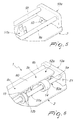
- the reference numeral 1 designates a link of a conveyor chain according to the invention, which is constituted by a main base body 2, which is approximately flat and has an approximately rectangular plan shape.
- Two wings 6 can protrude downward from the base body 2, in its central region, and are preferably L-shaped and arranged symmetrically with respect to a central plane of the link 1.
- the link 1 comprises known connection means for articulated connection to a similar and adjacent link, so as to allow the provision of a conveyor chain which is constituted by a succession of several links 1, which are mutually identical and are arranged consecutively with respect to each other along the advancement direction of said chain.
- connection means for articulated connection are constituted by a lug 3, which is arranged between the wings 6, protrudes at the front and centrally from the main base body 2, and has an approximately trapezoidal plan shape, with its smaller parallel side directed forward.
- a first bush or a hole 4 is formed on the lug 3, proximate to its front end 3a, and its axis is arranged transversely with respect to the advancement direction of the conveyor chain.
- the lug 3 can be accommodated within an approximately complementarily shaped first seat 5, which is formed centrally at the rear edge 2a of the main base body 2 of an adjacent link 1; the first seat 5 has, in plan view, an approximately rectangular shape, which is slightly wider than the lug 3, and is open at the rear edge 2a, so as to allow the insertion of said lug within said seat with a chosen functional play.
- Two ridges 7 are formed on the wings 6 at said lateral edges of the first seat 5, and a receptacle 7a is formed therein, has a preferably circular cross-section and is open toward the inside of the link 1, in order to support the ends of a transverse pivot, not shown in the figure, which can be inserted within the through slot or hole formed in the lug 3 so as to ensure the connection between two consecutive links 1.
- Said pivot has a smaller diameter than the through slot or hole; since the first seat 5 further is wider than the lug 3, relative rotation between two adjacent links 1 on the conveyance plane is allowed and occurs at curved portions of the conveyor chain.
- the link of conveyor chain 1 according to the invention can therefore be used both to provide straight conveyance portions and curved conveyance portions, according to the requirements of each specific case.
- Two tabs 8 can protrude radially in the opposite direction from the lower ends of the wings 6, each protruding toward the outside of the link 1; the tabs 8 can be inserted slidingly within complementarily shaped seats formed on a guide, which is not shown in the figures, and which slidingly supports the links 1, so as to contrast forces which act in the direction for lifting said links and can occur for example at curved portions of the conveyor chain.
- Two shoulders 10a and 10b protrude upward at the lateral ends of the transverse sides of the main base body 2 and are arranged parallel to the advancement direction of the chain; suitable first 10c and second 10d seats are formed thereon and are mutually aligned along axes which are longitudinal with respect to the main base body 2 and transverse to the advancement direction of the chain, with which the ends of two first and second shafts, designated by the reference numerals 9a and 9b, are rotatably associated, said shafts being arranged on a same plane which is approximately parallel to the plane of arrangement of the surface of the main base body 2 from which the two shoulders 10a and 10b protrude.
- first and second shafts 9a and 9b are parallel to each other and to the sides of the respective shoulder 10a and 10b, so as to leave a clear central seat; a plurality of first axially perforated rollers 14 are further rotatably associated with each one of the first and second shafts 9a and 9b, in particular with the shafts inserted therethrough.
- At least two first supporting elements protrude upward from the main base body 2, each element being constituted by two protrusions 12a, 12b and 12c, 12d, which are arranged in pairs on the same plane or on a separate plane which lies transversely to said pair of first and second shafts.
- Each protrusion 12a, 12b, 12c, 12d has, in plan view, an approximately rectangular shape, is parallel to the shoulders 10a and 10b, and is advantageously arranged in a mirror-symmetrical manner with respect to the central axis which lies transversely to the main base body 2.
- Each protrusion 12a, 12b, 12c, 12d, in a side view, is shaped approximately like an inverted right-angled trapezoid, in which the shorter parallel side is arranged upward and the longer parallel side is rigidly coupled to the main base body.
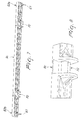
- each protrusion 12a, 12b, 12c, 12d there are provided, at the shorter parallel side, one or more third seats 13, which are approximately semicircular in cross-section and on which the complementarily shaped lateral surfaces of a second roller 15 interact in the loading condition for said link, said roller being perforated axially and having a diameter which is smaller than the diameter of the first rollers 14 and of the third seats 13.
- the first rollers 14 are arranged along the entire axis of the pair of first and second shafts 9a and 9b, except for the regions where the two protrusions 12a, 12b and 12c, 12d protrude from the main base body 2, and second rollers 15 engage in such protrusions; the second rollers 15 advantageously have a rolling surface which is centrally concave and is arranged between two flat lateral shoulders thereof. Since the second rollers 15 have a smaller diameter than the third seats 13 and are supported rotatably by the pair of first and second shafts 9a and 9b, they do not rest on said third seats when said pair of lateral shafts is arranged in a straight configuration, for example when no load is present on the first rollers 14.
- the link further comprises a slider 9c, which has an upper surface 60 which lies on a plane which is approximately tangent to the adjacent lateral surfaces of the first rollers associated with said first and second shafts.
- the slider 9c is interposed advantageously between said first and second shafts 9a, 9b and is supported by at least one pair of second supporting elements, which protrude from the main base body 2 and are each constituted by two lugs 51a and 51b, which have a slotted incision or guide in the upper surface which is adapted to receive and support a complementarily shaped ridge 70, which protrudes downward from said slider 9c.
- the two lugs 51a and 51b are arranged along a distinct plane, which is transverse with respect to the slider 9c and is also distinct with respect to the plane of arrangement of said first supporting elements 12a, 12b, 12c, 12d.
- said two lugs are each arranged in the space that is not comprised between said pair of first supporting elements 12a, 12b, 12c, 12d and are therefore adjacent to said pair of shoulders.
- the slider 9c further has its ends 52a and 52b free and not connected to the two shoulders 10a and 10b.
- End lugs 61 protrude downward from the ends 52a and 52b and are approximately shaped like a triangle with a rounded vertex which acts rotatably on complementarily shaped guides 53a and 53b, which protrude from the main base body 2 in a region which is adjacent to the pair of shoulders 10a and 10b.
- the operation of the link of conveyor chain according to the invention entails that if no load or a light load, constituted for example by an empty bottle, is present thereon, the pair of first and second shafts 9a and 9b has an approximately straight non-deformed configuration, so that the second rollers 15 are raised with respect to the respective facing third seat 13.
- first and second shafts 9a and 9b is rotatably associated only with the shoulders 10a and 10b, while the first and second rollers 14 and 15 are free to rotate in order to allow relative sliding of the product supported thereby with respect to the link 1, for example if said product supported thereby is locked in a chosen position by a retention barrier; low drag opposing the advancement of the conveyor chain is thus generated.
- the two first and second shafts 9a and 9b are arranged according to a deformed configuration; if the weight of said load exceeds a preset value, which can be defined for example analytically or experimentally, the lateral surface of the second rollers 15 makes contact with the corresponding surface of the third seat 13, so as to constitute a supporting point for the two first and second shafts.
- a preset value which can be defined for example analytically or experimentally
- the second rollers 15 do not rotate freely, since they are locked by the friction between its lateral surface and the surface of the third seat 13; the presence of the second rollers 15, however, avoids the wear of the protrusions 12a, 12b, 12c and 12d, since there is no direct contact with the two first and second shafts, which rotate, and the surface of the third seat 13, which is fixed.
- the second rollers 15 rest on the surface of the third seat 13, remaining locked in their rotation, only if the weight of the conveyed load exceeds a preset value; wear processes are thus slowed further, since if a lightweight load is conveyed, the second rollers 15 are not in contact with the protrusions and therefore can rotate freely, no action being applied to the protrusions.
- the presence of the second rollers 15 allows to obtain good uniformity of the upper loading surface, since the difference between the outside diameters of the first and second rollers can be very small; good positioning is therefore insured even in the case of products which have a narrow resting base.
- the presence of the surface 60 of the slider further allows to support bulky loads in an optimum manner.
- the invention allows optimum positioning of the conveyed products, even if said products have a narrow resting base or are constituted by bulky loads.
Landscapes
- Engineering & Computer Science (AREA)
- Mechanical Engineering (AREA)
- Chain Conveyers (AREA)
- Formation And Processing Of Food Products (AREA)
- Structure Of Belt Conveyors (AREA)
- Drying Of Solid Materials (AREA)
- Escalators And Moving Walkways (AREA)
- Hinges (AREA)
Applications Claiming Priority (1)
| Application Number | Priority Date | Filing Date | Title |
|---|---|---|---|
| IT000120A ITTV20050120A1 (it) | 2005-08-12 | 2005-08-12 | Maglia di catena trasportatrice |
Publications (3)
| Publication Number | Publication Date |
|---|---|
| EP1752395A2 true EP1752395A2 (de) | 2007-02-14 |
| EP1752395A3 EP1752395A3 (de) | 2008-07-30 |
| EP1752395B1 EP1752395B1 (de) | 2009-12-23 |
Family
ID=37398680
Family Applications (1)
| Application Number | Title | Priority Date | Filing Date |
|---|---|---|---|
| EP06117237A Not-in-force EP1752395B1 (de) | 2005-08-12 | 2006-07-14 | Förderkettengelenk |
Country Status (5)
| Country | Link |
|---|---|
| US (1) | US7757838B2 (de) |
| EP (1) | EP1752395B1 (de) |
| AT (1) | ATE452842T1 (de) |
| DE (1) | DE602006011245D1 (de) |
| IT (1) | ITTV20050120A1 (de) |
Families Citing this family (7)
| Publication number | Priority date | Publication date | Assignee | Title |
|---|---|---|---|---|
| EP2105391B1 (de) * | 2008-03-28 | 2012-02-22 | Ammeraal Beltech Modular A/S | Kettengliedmodul für eine akkumulierende Kette |
| DE102012104891B4 (de) | 2012-06-05 | 2024-03-28 | Krones Aktiengesellschaft | Mehrgliedriger Fördergurt mit Laufrollen |
| WO2014066607A1 (en) * | 2012-10-25 | 2014-05-01 | Rexnord Industries, Llc | Active control roller top modular conveying assembly |
| USD735434S1 (en) * | 2013-03-01 | 2015-07-28 | Mayfran International, Inc. | Plate with inner cleat |
| NL2015697B1 (en) * | 2015-10-30 | 2017-05-31 | Rexnord Flattop Europe Bv | Conveyor system, modular conveyor chain and injection molded plastic chain module. |
| MX2024009470A (es) * | 2022-02-21 | 2024-08-09 | Laitram Llc | Banda transportadora con rodillos en linea de doble apilado accionada por zonas. |
| USD1052219S1 (en) * | 2024-05-16 | 2024-11-19 | Makeblock Co., Ltd. | Conveyor rail |
Family Cites Families (14)
| Publication number | Priority date | Publication date | Assignee | Title |
|---|---|---|---|---|
| US2494302A (en) | 1945-11-05 | 1950-01-10 | James J Mason | Articulated conveyer |
| US3554360A (en) * | 1968-08-12 | 1971-01-12 | Seatech Engineering | Conveyor |
| US3853276A (en) * | 1972-10-11 | 1974-12-10 | Sprout Waldron & Co Inc | Reversible refiner feeder |
| EP0152639B1 (de) * | 1982-02-22 | 1988-02-10 | Rexnord Inc. | Förderkette für geringen Staudruck |
| DE3541364C2 (de) | 1985-06-17 | 1995-11-09 | Rexnord Corp | Tragglied für Gliederbandförderer |
| ES2027274T3 (es) * | 1986-12-24 | 1992-06-01 | M.A.F.(Materiel Pour L'arboriculture Fruitiere) S.A. | Aparato para la clasificacion automatica de productos agricolas tales como frutos. |
| US5344001A (en) * | 1992-02-28 | 1994-09-06 | Tsubakimoto Chain Co. | Conveyor chain with protective covers |
| US5314059A (en) * | 1992-10-29 | 1994-05-24 | Tekno, Inc. | Conveyor frame for chain conveyor |
| US6148990A (en) * | 1998-11-02 | 2000-11-21 | The Laitram Corporation | Modular roller-top conveyor belt |
| NL1010530C2 (nl) | 1998-11-11 | 2000-05-15 | Mcc Nederland | Modulaire transportmat, alsmede module voor een modulaire transportmat. |
| DE10027229A1 (de) | 2000-05-31 | 2001-12-06 | Flexon Systemplast Gmbh | Förderkette mit Kettengliedern aus mindestens zwei unterschiedlichen Materialien |
| US6997309B2 (en) * | 2003-03-03 | 2006-02-14 | Rexnord Industries, Inc. | Roller cradle and modular conveying assembly formed therefrom |
| US7234587B2 (en) * | 2005-01-06 | 2007-06-26 | Plastomeccanica S.P.A. | Conveyor chain link |
| ITTV20050121A1 (it) * | 2005-08-12 | 2007-02-13 | Plastomeccanica Spa | Maglia di catena trasportatrice |
-
2005
- 2005-08-12 IT IT000120A patent/ITTV20050120A1/it unknown
-
2006
- 2006-07-06 US US11/480,987 patent/US7757838B2/en not_active Expired - Fee Related
- 2006-07-14 DE DE602006011245T patent/DE602006011245D1/de not_active Expired - Fee Related
- 2006-07-14 EP EP06117237A patent/EP1752395B1/de not_active Not-in-force
- 2006-07-14 AT AT06117237T patent/ATE452842T1/de not_active IP Right Cessation
Also Published As
| Publication number | Publication date |
|---|---|
| EP1752395A3 (de) | 2008-07-30 |
| ATE452842T1 (de) | 2010-01-15 |
| US20070034485A1 (en) | 2007-02-15 |
| US7757838B2 (en) | 2010-07-20 |
| EP1752395B1 (de) | 2009-12-23 |
| DE602006011245D1 (de) | 2010-02-04 |
| ITTV20050120A1 (it) | 2007-02-13 |
Similar Documents
| Publication | Publication Date | Title |
|---|---|---|
| AU2010212338B2 (en) | Support device for conveying heavy loads | |
| EP0412059B1 (de) | Einstellbares Sternförderrad für runde und nicht runde Behälter | |
| US7578384B2 (en) | Link of conveyor chain | |
| US12168578B2 (en) | Collector with diverter apparatus for collecting articles | |
| KR200390957Y1 (ko) | 방향전환용 롤러가 장착된 체인형 콘베이어 | |
| EP1752395B1 (de) | Förderkettengelenk | |
| AU2010206045A1 (en) | A support device for a conveyor installation and method for operation of a conveyor installation | |
| US7234587B2 (en) | Conveyor chain link | |
| JP2018144958A (ja) | コンベヤ装置 | |
| CN104364172B (zh) | 具有辊轮的多环节传送带 | |
| EP2505518B1 (de) | Rollenförderermodul | |
| CN103708224A (zh) | 输送物的输送装置 | |
| KR101968096B1 (ko) | 방향전환기능을 갖는 컨베이어 장치 | |
| US20140014477A1 (en) | Conveyor system | |
| US11400492B2 (en) | Sorting device | |
| US20060225991A1 (en) | Unit for use in automatic container return systems | |
| CN103476691A (zh) | 传送装置 | |
| JP2018520076A (ja) | 自由回転ローラーと格納可能なフライトを有するチェーンコンベヤ | |
| EP3599191B1 (de) | Förderervorrichtung | |
| KR960010529B1 (ko) | 물품 분류 컨베이어 장치 | |
| JP4999697B2 (ja) | 少なくとも2つのコンベア間で荷物を載せ替えるための装置 | |
| KR20240116076A (ko) | 물류 이송 시스템 | |
| KR20030037435A (ko) | 벨트 컨베이어의 사행조정장치 | |
| JP5976587B2 (ja) | 容器集合装置 | |
| JPH0748022A (ja) | 仕分方法及び仕分装置 |
Legal Events
| Date | Code | Title | Description |
|---|---|---|---|
| PUAI | Public reference made under article 153(3) epc to a published international application that has entered the european phase |
Free format text: ORIGINAL CODE: 0009012 |
|
| AK | Designated contracting states |
Kind code of ref document: A2 Designated state(s): AT BE BG CH CY CZ DE DK EE ES FI FR GB GR HU IE IS IT LI LT LU LV MC NL PL PT RO SE SI SK TR |
|
| AX | Request for extension of the european patent |
Extension state: AL BA HR MK YU |
|
| PUAL | Search report despatched |
Free format text: ORIGINAL CODE: 0009013 |
|
| AK | Designated contracting states |
Kind code of ref document: A3 Designated state(s): AT BE BG CH CY CZ DE DK EE ES FI FR GB GR HU IE IS IT LI LT LU LV MC NL PL PT RO SE SI SK TR |
|
| AX | Request for extension of the european patent |
Extension state: AL BA HR MK RS |
|
| RAP1 | Party data changed (applicant data changed or rights of an application transferred) |
Owner name: HABASIT AG |
|
| 17P | Request for examination filed |
Effective date: 20090121 |
|
| AKX | Designation fees paid |
Designated state(s): AT BE BG CH CY CZ DE DK EE ES FI FR GB GR HU IE IS IT LI LT LU LV MC NL PL PT RO SE SI SK TR |
|
| GRAP | Despatch of communication of intention to grant a patent |
Free format text: ORIGINAL CODE: EPIDOSNIGR1 |
|
| GRAS | Grant fee paid |
Free format text: ORIGINAL CODE: EPIDOSNIGR3 |
|
| GRAA | (expected) grant |
Free format text: ORIGINAL CODE: 0009210 |
|
| AK | Designated contracting states |
Kind code of ref document: B1 Designated state(s): AT BE BG CH CY CZ DE DK EE ES FI FR GB GR HU IE IS IT LI LT LU LV MC NL PL PT RO SE SI SK TR |
|
| REG | Reference to a national code |
Ref country code: GB Ref legal event code: FG4D |
|
| REG | Reference to a national code |
Ref country code: CH Ref legal event code: EP |
|
| REG | Reference to a national code |
Ref country code: IE Ref legal event code: FG4D |
|
| REF | Corresponds to: |
Ref document number: 602006011245 Country of ref document: DE Date of ref document: 20100204 Kind code of ref document: P |
|
| REG | Reference to a national code |
Ref country code: NL Ref legal event code: VDEP Effective date: 20091223 |
|
| PG25 | Lapsed in a contracting state [announced via postgrant information from national office to epo] |
Ref country code: FI Free format text: LAPSE BECAUSE OF FAILURE TO SUBMIT A TRANSLATION OF THE DESCRIPTION OR TO PAY THE FEE WITHIN THE PRESCRIBED TIME-LIMIT Effective date: 20091223 Ref country code: LT Free format text: LAPSE BECAUSE OF FAILURE TO SUBMIT A TRANSLATION OF THE DESCRIPTION OR TO PAY THE FEE WITHIN THE PRESCRIBED TIME-LIMIT Effective date: 20091223 Ref country code: SE Free format text: LAPSE BECAUSE OF FAILURE TO SUBMIT A TRANSLATION OF THE DESCRIPTION OR TO PAY THE FEE WITHIN THE PRESCRIBED TIME-LIMIT Effective date: 20091223 |
|
| LTIE | Lt: invalidation of european patent or patent extension |
Effective date: 20091223 |
|
| PG25 | Lapsed in a contracting state [announced via postgrant information from national office to epo] |
Ref country code: SI Free format text: LAPSE BECAUSE OF FAILURE TO SUBMIT A TRANSLATION OF THE DESCRIPTION OR TO PAY THE FEE WITHIN THE PRESCRIBED TIME-LIMIT Effective date: 20091223 Ref country code: LV Free format text: LAPSE BECAUSE OF FAILURE TO SUBMIT A TRANSLATION OF THE DESCRIPTION OR TO PAY THE FEE WITHIN THE PRESCRIBED TIME-LIMIT Effective date: 20091223 Ref country code: PL Free format text: LAPSE BECAUSE OF FAILURE TO SUBMIT A TRANSLATION OF THE DESCRIPTION OR TO PAY THE FEE WITHIN THE PRESCRIBED TIME-LIMIT Effective date: 20091223 |
|
| PG25 | Lapsed in a contracting state [announced via postgrant information from national office to epo] |
Ref country code: AT Free format text: LAPSE BECAUSE OF FAILURE TO SUBMIT A TRANSLATION OF THE DESCRIPTION OR TO PAY THE FEE WITHIN THE PRESCRIBED TIME-LIMIT Effective date: 20091223 |
|
| PG25 | Lapsed in a contracting state [announced via postgrant information from national office to epo] |
Ref country code: BG Free format text: LAPSE BECAUSE OF FAILURE TO SUBMIT A TRANSLATION OF THE DESCRIPTION OR TO PAY THE FEE WITHIN THE PRESCRIBED TIME-LIMIT Effective date: 20100323 Ref country code: NL Free format text: LAPSE BECAUSE OF FAILURE TO SUBMIT A TRANSLATION OF THE DESCRIPTION OR TO PAY THE FEE WITHIN THE PRESCRIBED TIME-LIMIT Effective date: 20091223 Ref country code: IS Free format text: LAPSE BECAUSE OF FAILURE TO SUBMIT A TRANSLATION OF THE DESCRIPTION OR TO PAY THE FEE WITHIN THE PRESCRIBED TIME-LIMIT Effective date: 20100423 Ref country code: EE Free format text: LAPSE BECAUSE OF FAILURE TO SUBMIT A TRANSLATION OF THE DESCRIPTION OR TO PAY THE FEE WITHIN THE PRESCRIBED TIME-LIMIT Effective date: 20091223 Ref country code: ES Free format text: LAPSE BECAUSE OF FAILURE TO SUBMIT A TRANSLATION OF THE DESCRIPTION OR TO PAY THE FEE WITHIN THE PRESCRIBED TIME-LIMIT Effective date: 20100403 Ref country code: PT Free format text: LAPSE BECAUSE OF FAILURE TO SUBMIT A TRANSLATION OF THE DESCRIPTION OR TO PAY THE FEE WITHIN THE PRESCRIBED TIME-LIMIT Effective date: 20100423 Ref country code: RO Free format text: LAPSE BECAUSE OF FAILURE TO SUBMIT A TRANSLATION OF THE DESCRIPTION OR TO PAY THE FEE WITHIN THE PRESCRIBED TIME-LIMIT Effective date: 20091223 |
|
| PG25 | Lapsed in a contracting state [announced via postgrant information from national office to epo] |
Ref country code: SK Free format text: LAPSE BECAUSE OF FAILURE TO SUBMIT A TRANSLATION OF THE DESCRIPTION OR TO PAY THE FEE WITHIN THE PRESCRIBED TIME-LIMIT Effective date: 20091223 Ref country code: BE Free format text: LAPSE BECAUSE OF FAILURE TO SUBMIT A TRANSLATION OF THE DESCRIPTION OR TO PAY THE FEE WITHIN THE PRESCRIBED TIME-LIMIT Effective date: 20091223 Ref country code: CZ Free format text: LAPSE BECAUSE OF FAILURE TO SUBMIT A TRANSLATION OF THE DESCRIPTION OR TO PAY THE FEE WITHIN THE PRESCRIBED TIME-LIMIT Effective date: 20091223 |
|
| PG25 | Lapsed in a contracting state [announced via postgrant information from national office to epo] |
Ref country code: GR Free format text: LAPSE BECAUSE OF FAILURE TO SUBMIT A TRANSLATION OF THE DESCRIPTION OR TO PAY THE FEE WITHIN THE PRESCRIBED TIME-LIMIT Effective date: 20100324 Ref country code: CY Free format text: LAPSE BECAUSE OF FAILURE TO SUBMIT A TRANSLATION OF THE DESCRIPTION OR TO PAY THE FEE WITHIN THE PRESCRIBED TIME-LIMIT Effective date: 20091223 |
|
| PLBE | No opposition filed within time limit |
Free format text: ORIGINAL CODE: 0009261 |
|
| STAA | Information on the status of an ep patent application or granted ep patent |
Free format text: STATUS: NO OPPOSITION FILED WITHIN TIME LIMIT |
|
| 26N | No opposition filed |
Effective date: 20100924 |
|
| PG25 | Lapsed in a contracting state [announced via postgrant information from national office to epo] |
Ref country code: DK Free format text: LAPSE BECAUSE OF FAILURE TO SUBMIT A TRANSLATION OF THE DESCRIPTION OR TO PAY THE FEE WITHIN THE PRESCRIBED TIME-LIMIT Effective date: 20091223 |
|
| PG25 | Lapsed in a contracting state [announced via postgrant information from national office to epo] |
Ref country code: MC Free format text: LAPSE BECAUSE OF NON-PAYMENT OF DUE FEES Effective date: 20100731 |
|
| REG | Reference to a national code |
Ref country code: CH Ref legal event code: PL |
|
| GBPC | Gb: european patent ceased through non-payment of renewal fee |
Effective date: 20100714 |
|
| PG25 | Lapsed in a contracting state [announced via postgrant information from national office to epo] |
Ref country code: IT Free format text: LAPSE BECAUSE OF FAILURE TO SUBMIT A TRANSLATION OF THE DESCRIPTION OR TO PAY THE FEE WITHIN THE PRESCRIBED TIME-LIMIT Effective date: 20091223 |
|
| REG | Reference to a national code |
Ref country code: FR Ref legal event code: ST Effective date: 20110331 |
|
| PG25 | Lapsed in a contracting state [announced via postgrant information from national office to epo] |
Ref country code: DE Free format text: LAPSE BECAUSE OF NON-PAYMENT OF DUE FEES Effective date: 20110201 Ref country code: LI Free format text: LAPSE BECAUSE OF NON-PAYMENT OF DUE FEES Effective date: 20100731 Ref country code: CH Free format text: LAPSE BECAUSE OF NON-PAYMENT OF DUE FEES Effective date: 20100731 |
|
| REG | Reference to a national code |
Ref country code: DE Ref legal event code: R119 Ref document number: 602006011245 Country of ref document: DE Effective date: 20110201 |
|
| PG25 | Lapsed in a contracting state [announced via postgrant information from national office to epo] |
Ref country code: FR Free format text: LAPSE BECAUSE OF NON-PAYMENT OF DUE FEES Effective date: 20100802 |
|
| PG25 | Lapsed in a contracting state [announced via postgrant information from national office to epo] |
Ref country code: GB Free format text: LAPSE BECAUSE OF NON-PAYMENT OF DUE FEES Effective date: 20100714 Ref country code: IE Free format text: LAPSE BECAUSE OF NON-PAYMENT OF DUE FEES Effective date: 20100714 |
|
| PG25 | Lapsed in a contracting state [announced via postgrant information from national office to epo] |
Ref country code: LU Free format text: LAPSE BECAUSE OF NON-PAYMENT OF DUE FEES Effective date: 20100714 Ref country code: HU Free format text: LAPSE BECAUSE OF FAILURE TO SUBMIT A TRANSLATION OF THE DESCRIPTION OR TO PAY THE FEE WITHIN THE PRESCRIBED TIME-LIMIT Effective date: 20100624 |
|
| PG25 | Lapsed in a contracting state [announced via postgrant information from national office to epo] |
Ref country code: TR Free format text: LAPSE BECAUSE OF FAILURE TO SUBMIT A TRANSLATION OF THE DESCRIPTION OR TO PAY THE FEE WITHIN THE PRESCRIBED TIME-LIMIT Effective date: 20091223 |