EP1752745B1 - Cuillère avec cellule de pesage - Google Patents
Cuillère avec cellule de pesage Download PDFInfo
- Publication number
- EP1752745B1 EP1752745B1 EP06014771A EP06014771A EP1752745B1 EP 1752745 B1 EP1752745 B1 EP 1752745B1 EP 06014771 A EP06014771 A EP 06014771A EP 06014771 A EP06014771 A EP 06014771A EP 1752745 B1 EP1752745 B1 EP 1752745B1
- Authority
- EP
- European Patent Office
- Prior art keywords
- spoon
- sensor
- handle
- weight sensor
- horizontal
- Prior art date
- Legal status (The legal status is an assumption and is not a legal conclusion. Google has not performed a legal analysis and makes no representation as to the accuracy of the status listed.)
- Not-in-force
Links
- 238000005259 measurement Methods 0.000 claims description 4
- 239000000725 suspension Substances 0.000 description 6
- 238000007789 sealing Methods 0.000 description 3
- XLYOFNOQVPJJNP-UHFFFAOYSA-N water Substances O XLYOFNOQVPJJNP-UHFFFAOYSA-N 0.000 description 3
- 239000013590 bulk material Substances 0.000 description 2
- 238000010411 cooking Methods 0.000 description 2
- 239000000463 material Substances 0.000 description 2
- 238000005303 weighing Methods 0.000 description 2
- XVIZMMSINIOIQP-UHFFFAOYSA-N 1,2-dichloro-3-(2-chlorophenyl)benzene Chemical compound ClC1=CC=CC(C=2C(=CC=CC=2)Cl)=C1Cl XVIZMMSINIOIQP-UHFFFAOYSA-N 0.000 description 1
- 235000012820 baking ingredients and mixes Nutrition 0.000 description 1
- 238000006243 chemical reaction Methods 0.000 description 1
- 238000010276 construction Methods 0.000 description 1
- 230000001419 dependent effect Effects 0.000 description 1
- 238000000691 measurement method Methods 0.000 description 1
- 235000013599 spices Nutrition 0.000 description 1
- 230000001960 triggered effect Effects 0.000 description 1
- 239000011800 void material Substances 0.000 description 1
Images



Classifications
-
- G—PHYSICS
- G01—MEASURING; TESTING
- G01G—WEIGHING
- G01G19/00—Weighing apparatus or methods adapted for special purposes not provided for in the preceding groups
- G01G19/52—Weighing apparatus combined with other objects, e.g. furniture
- G01G19/56—Weighing apparatus combined with other objects, e.g. furniture combined with handles of tools or household implements
-
- A—HUMAN NECESSITIES
- A47—FURNITURE; DOMESTIC ARTICLES OR APPLIANCES; COFFEE MILLS; SPICE MILLS; SUCTION CLEANERS IN GENERAL
- A47G—HOUSEHOLD OR TABLE EQUIPMENT
- A47G21/00—Table-ware
- A47G21/02—Forks; Forks with ejectors; Combined forks and spoons; Salad servers
Definitions
- the present invention relates to a spoon scale, especially for use in determining the weight of various spices in cooking.
- spoons are simple one-piece items without any additional features.
- spoons can not be used to determine the amount of items on the spoon.
- Such spoons can not meet the requirements of users in determining the weight of cooking and baking ingredients. The information "a teaspoon” or "a tablespoon” are inaccurate.
- the Japanese document JP 59067425 A shows a scale for microscopic objects.
- the scale comprises a base body and a spoon-like shell.
- the shell is connected via a stem to the base body.
- Load sensors are glued to the top and bottom of the handle.
- This scale is not equipped with a handle in the manner of a spoon and therefore unsuitable for use in the home.
- the document US 2005/0011367 A1 shows a spoon with a weight sensor not described in detail.
- the dipper stick is threaded into the handle and can be exchanged for a fork handle or the like. It is a maximum weight for a portion located on the spoon vorciclbar above which a warning signal should be triggered.
- the US Pat. No. 6,573,462 B1 finally shows a blade for measuring bulk material.
- a load sensor is arranged, which is fastened with a perpendicular to the horizontal contact surface arranged on the handle. About this contact surface, the entire weight is transmitted. Therefore, the expansion in the vertical direction is relatively large.
- the sensor is not integrated in the handle, but in an adjacent, enlarged housing section. This will make the scale unwieldy.
- the invention provides a bucket type bucket comprising a bucket body, a handle, a horizontal sensor and a hanger ring.
- the bucket body includes the bucket head and the bucket head attachment.
- the spoon head connection is connected to a weight sensor, which is arranged inside the handle.
- the handle may be provided with a hanger ring to hang the spoon for storage purposes.
- An LCD display may be further disposed within the handle. To display the amount of material placed on the bucket head via the LCD display, the weight sensor is connected to the LCD display via an analog-to-digital converter and a microcontroller.
- the horizontal sensor is located in the handle to ensure horizontal alignment of the bucket when performing weighing operations.
- the housing of the described handle may be composed of a lens, an operating knob, the horizontal sensor, the top cover, the bottom cover, and the battery cover.
- the control knob and the battery can also be arranged inside the housing.
- Such an actuating knob made of rubber is connected to a push button, which is provided within the lens or housing half arranged above.
- a circuit board is located under the rubber button.
- the LCD display described is arranged between the lens and the board next to the rubber button. To connect the circuits together, an electrically conductive rubber material is disposed between the LCD display and the circuit board.
- the horizontal sensor and the LCD display are placed on the same side of the handle, which corresponds to the concave side of the spoon head.
- a battery terminal plate is mounted on the other side of the board in a corresponding location.
- This battery terminal plate is connected to the battery already described, which is arranged underneath.
- the battery is in turn disposed between the battery terminal plate and the battery cover.
- a sealing ring is provided between the battery cover and the lower shell half to improve water resistance.
- the described horizontal sensor is placed in an opening of the lens arranged on the handle. This opening is positioned at that end of the lens that is close to the junction with the top cover.
- the horizontal sensor is used to ensure that accurate readings are achieved when the bucket is held horizontally.
- the load direction on the weight sensor is perpendicular to the horizontal plane.
- the battery cover is arranged at that end of the handle on which the suspension ring is arranged.
- a concave trough is formed in the described lower cover to attach the battery cover there can.
- Such a battery cover is screwed to the handle by means of a screw.
- the task of the battery is to supply the H / D converter and the microcontroller on the board with voltage, so that the LCD display can be controlled to display the objects on the spoon.
- the described spoon head and the spoon head connection are a one-piece structure.
- the shape of the spoon head can be varied to accommodate different applications.
- the Spindle Head Connector is connected to the weight sensor via screws.
- the weight sensor is disposed between the upper cover and the lower cover.
- the end of the weight sensor connected to the spoon head port is not in mechanical contact with the top cover and the bottom cover. However, the other end of the weight sensor is penetrated by screws extending from the bottom of the top cover to the bottom cover.
- the function of the present invention is to use an analog-to-digital converter, the microcontroller unit circuitry, and the pushbuttons to display the weight indication in response to the weight sensor on the LCD display when needed.
- the horizontal sensor makes it easier for the user to hold the device in the correct position.
- a suspension ring is provided to facilitate the storage of the spoon scale.
- the sealing ring improves the water resistance of this device.
- the device may be provided with a plurality of pressure switches, which include not only an on / off switch, but also a conversion of weight units and a holding function for the display.
- the spoon scale may also be provided with an automatic shut-off device that shuts off power when the weight indicator remains unchanged for a predetermined period of time or when no buttons are pressed. In this way, the battery capacity can be saved.
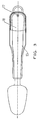
- a spoon is provided for weight measurement. Like in the FIG. 1 and the FIG. 2 shown, this comprises a spoon head 21, a spoon head connector 22, a handle 23, a horizontal sensor 7 and a suspension ring 1.
- the spoon head connection 22 is connected to the handle 23, while on the opposite side of the handle 23, the suspension device is provided.
- a weight sensor 12 and an LCD display 3 are arranged in the handle 23.
- the weight sensor 12 and the LCD display 3 are connected through the circuits of the analog-to-digital converter and the microcontroller to display the mass of objects within the bucket head 21 on the LCD display 3.
- the combination of a button 6 with the horizontal sensor 7 is arranged next to the weight sensor 12 and the LCD display 3.
- the spoon head 21 and the spoon head connection 22 are a one-piece piece and together are called the spoon body 11, as shown in the Figures 1-3 is shown.
- a void is provided between the weight sensor 12 and the upper cover 9, in which screws 10 and 8 are arranged.
- the plate-shaped spoon head connector 22 is connected to one end of the weight sensor 12 by screws 10.
- This weight sensor 12 is disposed between the upper cover 9 and the lower cover 13.
- the other end of the weight sensor is penetrated by screws 8, which connect the underside of the upper cover 9 and the lower cover 13 together.
- the upper cover 9 is connected to the lens 4 in the horizontal direction as well as the lower cover 13 located below.
- the entire shell of the handle 23 is composed of the lens 4, the button 6, the horizontal sensor 7, the upper Cover 9, lower cover 13 and battery cover 17. As in Figure 3-5 As shown, a rubber button 5 and a battery 16 are also provided inside the handle 23.
- the construction of the handle 23 will be explained in detail.
- the rubber button 5 is connected to the button located above 6, which in turn is embedded in the lens 4.
- the board 2 is disposed below the rubber button 5.
- the LCD display 3 is located between the board 2 and the lens 4 adjacent to the rubber button 5. Further, the electrically conductive rubber 19 is provided between the LCD display 3 and the board 2.
- the horizontal sensor 7 and the LCD display 3 are further arranged on the left and right of the knob 6.
- the battery board 15 is placed on the other side of the board at the location described above.
- the battery board is connected to the battery 16, which is disposed between the battery board 15 and the battery cover 18.
- a sealing ring 14 is also disposed between the battery cover 18 and the lower cover 13 to enhance the ability to withstand water.
- the horizontal sensor 7 attached to the handle 23 is disposed within an opening of the lens 4. This opening is located at one end of the lens 4, which is near the location where the lens 4 is connected to the top cover 9.
- the battery cover 18 is disposed at the end of the handle 23 to which the suspension ring 1 is also attached.
- a concave trough is formed in the lower cover 13 at this end to attach the battery cover 18 there.
- a screw 17 is used to screw the battery cover 18 to the bottom cover 13 on the handle 23.
Landscapes
- Physics & Mathematics (AREA)
- General Physics & Mathematics (AREA)
- Food-Manufacturing Devices (AREA)
- Table Equipment (AREA)
- Details Of Rigid Or Semi-Rigid Containers (AREA)
- Dry Shavers And Clippers (AREA)
- Photosensitive Polymer And Photoresist Processing (AREA)
Claims (6)
- Cuillère de pesée comprenant un manche (23), un corps de cuillère (11) et un capteur de poids (12), le manche comportant un capotage de fermeture supérieur (9) et un capotage de fermeture inférieur (13) et étant conçu pour être saisi et maintenu par la main d'un utilisateur, le capteur de poids (12) étant situé dans la ligne de transmission de force entre le corps de cuillère (11) et le manche (23), la direction de charge du capteur de poids étant d'une orientation perpendiculaire à un plan horizontal pour lequel est prévu un capteur d'horizontale (7), qui est conçu pour mesurer l'orientation de la cuillère de pesée par rapport au plan horizontal, et le corps de cuillère (11) présentant une tête de cuillère (21) et un raccord de tête de cuillère (22) agencé de manière à s'écarter de la tête de cuillère, caractérisée en ce que le capteur de poids (12) présente, à son extrémité éloignée du raccord de tête de cuillère (22), une surface d'appui orientée parallèlement au plan horizontal, et est relié, dans la zone de cette surface d'appui, au moyen de vis (8), au capotage de fermeture inférieur (13), les vis (8) étant orientées perpendiculairement au plan horizontal.
- Cuillère de pesée selon la revendication 1, caractérisée en ce que le corps de cuillère (11) ne se trouve pas en contact mécanique direct avec le manche (23), notamment avec un capotage de fermeture supérieur (9) ou un capotage de fermeture inférieur (13).
- Cuillère de pesée selon l'une des revendications précédentes, caractérisée en ce que la direction de charge du capteur de poids (12) est orienté perpendiculairement au plan horizontal, qui est relevé par le capteur d'horizontale (7).
- Cuillère de pesée selon l'une des revendications précédentes, caractérisée en ce que le capteur d'horizontale (7) est agencé dans une ouverture d'une lentille (4), sur le manche (23).
- Cuillère de pesée selon l'une des revendications précédentes, caractérisée en ce qu'une mesure de poids n'est exécutée que lorsque le capteur d'horizontale (7) détermine une inclinaison de la cuillère de pesée de moins de 5° par rapport au plan horizontal.
- Cuillère de pesée selon l'une des revendications précédentes, caractérisée en ce que le capteur de poids (12) est réalisé sous la forme d'un pont de résistances.
Applications Claiming Priority (2)
| Application Number | Priority Date | Filing Date | Title |
|---|---|---|---|
| CNU2005201035733U CN2817643Y (zh) | 2005-08-10 | 2005-08-10 | 称重匙羹 |
| DE200510062980 DE102005062980A1 (de) | 2005-08-10 | 2005-12-28 | Löffelwaage |
Publications (2)
| Publication Number | Publication Date |
|---|---|
| EP1752745A1 EP1752745A1 (fr) | 2007-02-14 |
| EP1752745B1 true EP1752745B1 (fr) | 2011-03-16 |
Family
ID=36992668
Family Applications (1)
| Application Number | Title | Priority Date | Filing Date |
|---|---|---|---|
| EP06014771A Not-in-force EP1752745B1 (fr) | 2005-08-10 | 2006-07-15 | Cuillère avec cellule de pesage |
Country Status (3)
| Country | Link |
|---|---|
| EP (1) | EP1752745B1 (fr) |
| AT (1) | ATE502285T1 (fr) |
| DE (2) | DE202005021807U1 (fr) |
Cited By (1)
| Publication number | Priority date | Publication date | Assignee | Title |
|---|---|---|---|---|
| DE202017100310U1 (de) | 2017-01-20 | 2017-02-06 | Face Moore International Limited | Löffelwaage |
Families Citing this family (2)
| Publication number | Priority date | Publication date | Assignee | Title |
|---|---|---|---|---|
| US9818310B2 (en) * | 2015-06-22 | 2017-11-14 | Verily Life Sciences Llc | Assessment of nutrition intake using a handheld tool |
| GR1010206B (el) * | 2021-06-14 | 2022-03-21 | Αγγελος Νικολαου Ευαγγελου | Ψηφιακη λαβιδα ζυγισης χειρος |
Family Cites Families (4)
| Publication number | Priority date | Publication date | Assignee | Title |
|---|---|---|---|---|
| JPS5967425A (ja) | 1982-10-12 | 1984-04-17 | Matsushita Electric Works Ltd | 計重装置 |
| US6236001B1 (en) | 1999-08-03 | 2001-05-22 | Wayne W. Shymko | Scoop with weigh scale |
| DE10125796A1 (de) | 2001-05-26 | 2002-12-05 | Daniel Hoesmann | Handwaage (digital bzw. elektronisch) |
| US20050011367A1 (en) | 2003-07-18 | 2005-01-20 | Crow Frederick W. | Portion control serving utensils |
-
2005
- 2005-12-28 DE DE202005021807U patent/DE202005021807U1/de not_active Expired - Lifetime
-
2006
- 2006-07-15 EP EP06014771A patent/EP1752745B1/fr not_active Not-in-force
- 2006-07-15 DE DE502006009090T patent/DE502006009090D1/de active Active
- 2006-07-15 AT AT06014771T patent/ATE502285T1/de active
Cited By (1)
| Publication number | Priority date | Publication date | Assignee | Title |
|---|---|---|---|---|
| DE202017100310U1 (de) | 2017-01-20 | 2017-02-06 | Face Moore International Limited | Löffelwaage |
Also Published As
| Publication number | Publication date |
|---|---|
| DE502006009090D1 (de) | 2011-04-28 |
| ATE502285T1 (de) | 2011-04-15 |
| DE202005021807U1 (de) | 2010-06-10 |
| EP1752745A1 (fr) | 2007-02-14 |
Similar Documents
| Publication | Publication Date | Title |
|---|---|---|
| EP1509752B1 (fr) | Dispositif de surveillance de l'etat de fonctionnement d'une balance | |
| CH693024A5 (de) | Multifunktionales Werkzeug. | |
| DE3639521C2 (de) | Elektrische Waage | |
| US6236001B1 (en) | Scoop with weigh scale | |
| DE501766C (de) | Verfahren und Vorrichtung zur Messung der Konsistenz von Beton | |
| DE2814789C2 (de) | Vorrichtung zum Überwachen des Niveaus einer Flüssigkeit in einem Behälter | |
| DE10308804A1 (de) | Waage | |
| EP1752745A1 (fr) | Cuillère avec cellule de pesage | |
| DE3208811A1 (de) | Neigungswinkelmessgeraet mit einer elektronisch gesteuerten, digitalen ziffernanzeige von neigungswinkeln bezogen auf die horizontale, mittels einer stufenlosen abtastung eines oder mehrerer elektrischer widerstaende durch die schwerkraft bewegungsgesteuerter pendel, kugeln, quecksilberperlen oder walzen | |
| WO1989003503A1 (fr) | Goniometre avec capteur electronique de mesure et affichage numerique | |
| DE102005062980A1 (de) | Löffelwaage | |
| DE19705645A1 (de) | Löffel mit Temperaturmeßeinrichtung | |
| EP2317900B1 (fr) | Robot ménager comportant une base munie de plusieurs pieds | |
| WO1997007384A1 (fr) | Balance | |
| DE102007031380B4 (de) | Waage | |
| DE10360266B4 (de) | Waage | |
| DE19924724C2 (de) | Waage | |
| DE10306195B4 (de) | Waage mit einer elektrischen Schaltvorrichtung | |
| DE10312784B4 (de) | Waage mit einer Lastplatte | |
| DE1938119B2 (de) | Einrichtung zum messen und analogen anzeigen des fluessigkeits niveaus in behaeltern | |
| US4112742A (en) | Instrument for measuring the consistency of high-consistency materials | |
| DE10018416C1 (de) | Modelleisenbahn-Gleiswaage | |
| DE2618493C3 (de) | Vorrichtung zur Tiefschußauswertung | |
| DE1938119C (de) | Einrichtung zum Messen und analogen Anzeigen des Flüssigkeitsniveaus in Behältern | |
| DE8903153U1 (de) | Elektronischer Winkelmesser |
Legal Events
| Date | Code | Title | Description |
|---|---|---|---|
| PUAI | Public reference made under article 153(3) epc to a published international application that has entered the european phase |
Free format text: ORIGINAL CODE: 0009012 |
|
| AK | Designated contracting states |
Kind code of ref document: A1 Designated state(s): AT BE BG CH CY CZ DE DK EE ES FI FR GB GR HU IE IS IT LI LT LU LV MC NL PL PT RO SE SI SK TR |
|
| AX | Request for extension of the european patent |
Extension state: AL BA HR MK YU |
|
| 17P | Request for examination filed |
Effective date: 20070803 |
|
| AKX | Designation fees paid |
Designated state(s): AT BE BG CH CY CZ DE DK EE ES FI FR GB GR HU IE IS IT LI LT LU LV MC NL PL PT RO SE SI SK TR |
|
| 17Q | First examination report despatched |
Effective date: 20071005 |
|
| GRAP | Despatch of communication of intention to grant a patent |
Free format text: ORIGINAL CODE: EPIDOSNIGR1 |
|
| GRAS | Grant fee paid |
Free format text: ORIGINAL CODE: EPIDOSNIGR3 |
|
| GRAA | (expected) grant |
Free format text: ORIGINAL CODE: 0009210 |
|
| AK | Designated contracting states |
Kind code of ref document: B1 Designated state(s): AT BE BG CH CY CZ DE DK EE ES FI FR GB GR HU IE IS IT LI LT LU LV MC NL PL PT RO SE SI SK TR |
|
| REG | Reference to a national code |
Ref country code: GB Ref legal event code: FG4D Free format text: NOT ENGLISH |
|
| REG | Reference to a national code |
Ref country code: CH Ref legal event code: EP |
|
| REG | Reference to a national code |
Ref country code: IE Ref legal event code: FG4D |
|
| REF | Corresponds to: |
Ref document number: 502006009090 Country of ref document: DE Date of ref document: 20110428 Kind code of ref document: P |
|
| REG | Reference to a national code |
Ref country code: DE Ref legal event code: R096 Ref document number: 502006009090 Country of ref document: DE Effective date: 20110428 |
|
| REG | Reference to a national code |
Ref country code: NL Ref legal event code: VDEP Effective date: 20110316 |
|
| PG25 | Lapsed in a contracting state [announced via postgrant information from national office to epo] |
Ref country code: LT Free format text: LAPSE BECAUSE OF FAILURE TO SUBMIT A TRANSLATION OF THE DESCRIPTION OR TO PAY THE FEE WITHIN THE PRESCRIBED TIME-LIMIT Effective date: 20110316 Ref country code: SE Free format text: LAPSE BECAUSE OF FAILURE TO SUBMIT A TRANSLATION OF THE DESCRIPTION OR TO PAY THE FEE WITHIN THE PRESCRIBED TIME-LIMIT Effective date: 20110316 Ref country code: GR Free format text: LAPSE BECAUSE OF FAILURE TO SUBMIT A TRANSLATION OF THE DESCRIPTION OR TO PAY THE FEE WITHIN THE PRESCRIBED TIME-LIMIT Effective date: 20110617 Ref country code: ES Free format text: LAPSE BECAUSE OF FAILURE TO SUBMIT A TRANSLATION OF THE DESCRIPTION OR TO PAY THE FEE WITHIN THE PRESCRIBED TIME-LIMIT Effective date: 20110627 Ref country code: LV Free format text: LAPSE BECAUSE OF FAILURE TO SUBMIT A TRANSLATION OF THE DESCRIPTION OR TO PAY THE FEE WITHIN THE PRESCRIBED TIME-LIMIT Effective date: 20110316 |
|
| LTIE | Lt: invalidation of european patent or patent extension |
Effective date: 20110316 |
|
| PG25 | Lapsed in a contracting state [announced via postgrant information from national office to epo] |
Ref country code: CY Free format text: LAPSE BECAUSE OF FAILURE TO SUBMIT A TRANSLATION OF THE DESCRIPTION OR TO PAY THE FEE WITHIN THE PRESCRIBED TIME-LIMIT Effective date: 20110316 Ref country code: BG Free format text: LAPSE BECAUSE OF FAILURE TO SUBMIT A TRANSLATION OF THE DESCRIPTION OR TO PAY THE FEE WITHIN THE PRESCRIBED TIME-LIMIT Effective date: 20110616 Ref country code: SI Free format text: LAPSE BECAUSE OF FAILURE TO SUBMIT A TRANSLATION OF THE DESCRIPTION OR TO PAY THE FEE WITHIN THE PRESCRIBED TIME-LIMIT Effective date: 20110316 Ref country code: FI Free format text: LAPSE BECAUSE OF FAILURE TO SUBMIT A TRANSLATION OF THE DESCRIPTION OR TO PAY THE FEE WITHIN THE PRESCRIBED TIME-LIMIT Effective date: 20110316 |
|
| REG | Reference to a national code |
Ref country code: IE Ref legal event code: FD4D |
|
| PG25 | Lapsed in a contracting state [announced via postgrant information from national office to epo] |
Ref country code: PT Free format text: LAPSE BECAUSE OF FAILURE TO SUBMIT A TRANSLATION OF THE DESCRIPTION OR TO PAY THE FEE WITHIN THE PRESCRIBED TIME-LIMIT Effective date: 20110718 Ref country code: EE Free format text: LAPSE BECAUSE OF FAILURE TO SUBMIT A TRANSLATION OF THE DESCRIPTION OR TO PAY THE FEE WITHIN THE PRESCRIBED TIME-LIMIT Effective date: 20110316 Ref country code: IE Free format text: LAPSE BECAUSE OF FAILURE TO SUBMIT A TRANSLATION OF THE DESCRIPTION OR TO PAY THE FEE WITHIN THE PRESCRIBED TIME-LIMIT Effective date: 20110316 |
|
| PG25 | Lapsed in a contracting state [announced via postgrant information from national office to epo] |
Ref country code: RO Free format text: LAPSE BECAUSE OF FAILURE TO SUBMIT A TRANSLATION OF THE DESCRIPTION OR TO PAY THE FEE WITHIN THE PRESCRIBED TIME-LIMIT Effective date: 20110316 Ref country code: CZ Free format text: LAPSE BECAUSE OF FAILURE TO SUBMIT A TRANSLATION OF THE DESCRIPTION OR TO PAY THE FEE WITHIN THE PRESCRIBED TIME-LIMIT Effective date: 20110316 Ref country code: IS Free format text: LAPSE BECAUSE OF FAILURE TO SUBMIT A TRANSLATION OF THE DESCRIPTION OR TO PAY THE FEE WITHIN THE PRESCRIBED TIME-LIMIT Effective date: 20110716 Ref country code: SK Free format text: LAPSE BECAUSE OF FAILURE TO SUBMIT A TRANSLATION OF THE DESCRIPTION OR TO PAY THE FEE WITHIN THE PRESCRIBED TIME-LIMIT Effective date: 20110316 |
|
| PGFP | Annual fee paid to national office [announced via postgrant information from national office to epo] |
Ref country code: GB Payment date: 20110720 Year of fee payment: 6 |
|
| PG25 | Lapsed in a contracting state [announced via postgrant information from national office to epo] |
Ref country code: NL Free format text: LAPSE BECAUSE OF FAILURE TO SUBMIT A TRANSLATION OF THE DESCRIPTION OR TO PAY THE FEE WITHIN THE PRESCRIBED TIME-LIMIT Effective date: 20110316 |
|
| PLBE | No opposition filed within time limit |
Free format text: ORIGINAL CODE: 0009261 |
|
| STAA | Information on the status of an ep patent application or granted ep patent |
Free format text: STATUS: NO OPPOSITION FILED WITHIN TIME LIMIT |
|
| BERE | Be: lapsed |
Owner name: MINGLE INSTRUMENT G.M.B.H. EUROPE Effective date: 20110731 |
|
| 26N | No opposition filed |
Effective date: 20111219 |
|
| PG25 | Lapsed in a contracting state [announced via postgrant information from national office to epo] |
Ref country code: PL Free format text: LAPSE BECAUSE OF FAILURE TO SUBMIT A TRANSLATION OF THE DESCRIPTION OR TO PAY THE FEE WITHIN THE PRESCRIBED TIME-LIMIT Effective date: 20110316 Ref country code: DK Free format text: LAPSE BECAUSE OF FAILURE TO SUBMIT A TRANSLATION OF THE DESCRIPTION OR TO PAY THE FEE WITHIN THE PRESCRIBED TIME-LIMIT Effective date: 20110316 Ref country code: MC Free format text: LAPSE BECAUSE OF NON-PAYMENT OF DUE FEES Effective date: 20110731 |
|
| REG | Reference to a national code |
Ref country code: CH Ref legal event code: PL |
|
| REG | Reference to a national code |
Ref country code: DE Ref legal event code: R097 Ref document number: 502006009090 Country of ref document: DE Effective date: 20111219 |
|
| PG25 | Lapsed in a contracting state [announced via postgrant information from national office to epo] |
Ref country code: CH Free format text: LAPSE BECAUSE OF NON-PAYMENT OF DUE FEES Effective date: 20110731 Ref country code: LI Free format text: LAPSE BECAUSE OF NON-PAYMENT OF DUE FEES Effective date: 20110731 Ref country code: BE Free format text: LAPSE BECAUSE OF NON-PAYMENT OF DUE FEES Effective date: 20110731 |
|
| PG25 | Lapsed in a contracting state [announced via postgrant information from national office to epo] |
Ref country code: IT Free format text: LAPSE BECAUSE OF FAILURE TO SUBMIT A TRANSLATION OF THE DESCRIPTION OR TO PAY THE FEE WITHIN THE PRESCRIBED TIME-LIMIT Effective date: 20110316 |
|
| REG | Reference to a national code |
Ref country code: AT Ref legal event code: MM01 Ref document number: 502285 Country of ref document: AT Kind code of ref document: T Effective date: 20110715 |
|
| PG25 | Lapsed in a contracting state [announced via postgrant information from national office to epo] |
Ref country code: AT Free format text: LAPSE BECAUSE OF NON-PAYMENT OF DUE FEES Effective date: 20110715 |
|
| GBPC | Gb: european patent ceased through non-payment of renewal fee |
Effective date: 20120715 |
|
| PG25 | Lapsed in a contracting state [announced via postgrant information from national office to epo] |
Ref country code: GB Free format text: LAPSE BECAUSE OF NON-PAYMENT OF DUE FEES Effective date: 20120715 |
|
| PG25 | Lapsed in a contracting state [announced via postgrant information from national office to epo] |
Ref country code: LU Free format text: LAPSE BECAUSE OF NON-PAYMENT OF DUE FEES Effective date: 20110715 |
|
| PG25 | Lapsed in a contracting state [announced via postgrant information from national office to epo] |
Ref country code: TR Free format text: LAPSE BECAUSE OF FAILURE TO SUBMIT A TRANSLATION OF THE DESCRIPTION OR TO PAY THE FEE WITHIN THE PRESCRIBED TIME-LIMIT Effective date: 20110316 |
|
| PG25 | Lapsed in a contracting state [announced via postgrant information from national office to epo] |
Ref country code: HU Free format text: LAPSE BECAUSE OF FAILURE TO SUBMIT A TRANSLATION OF THE DESCRIPTION OR TO PAY THE FEE WITHIN THE PRESCRIBED TIME-LIMIT Effective date: 20110316 |
|
| REG | Reference to a national code |
Ref country code: FR Ref legal event code: PLFP Year of fee payment: 11 |
|
| REG | Reference to a national code |
Ref country code: FR Ref legal event code: PLFP Year of fee payment: 12 |
|
| REG | Reference to a national code |
Ref country code: FR Ref legal event code: PLFP Year of fee payment: 13 |
|
| PGFP | Annual fee paid to national office [announced via postgrant information from national office to epo] |
Ref country code: DE Payment date: 20180724 Year of fee payment: 13 Ref country code: FR Payment date: 20180724 Year of fee payment: 13 |
|
| REG | Reference to a national code |
Ref country code: DE Ref legal event code: R119 Ref document number: 502006009090 Country of ref document: DE |
|
| PG25 | Lapsed in a contracting state [announced via postgrant information from national office to epo] |
Ref country code: DE Free format text: LAPSE BECAUSE OF NON-PAYMENT OF DUE FEES Effective date: 20200201 |
|
| PG25 | Lapsed in a contracting state [announced via postgrant information from national office to epo] |
Ref country code: FR Free format text: LAPSE BECAUSE OF NON-PAYMENT OF DUE FEES Effective date: 20190731 |