EP1753075A1 - Mast mit Schnellbefestigung für Funkkommunikationsantennen - Google Patents
Mast mit Schnellbefestigung für Funkkommunikationsantennen Download PDFInfo
- Publication number
- EP1753075A1 EP1753075A1 EP06291273A EP06291273A EP1753075A1 EP 1753075 A1 EP1753075 A1 EP 1753075A1 EP 06291273 A EP06291273 A EP 06291273A EP 06291273 A EP06291273 A EP 06291273A EP 1753075 A1 EP1753075 A1 EP 1753075A1
- Authority
- EP
- European Patent Office
- Prior art keywords
- antenna
- mast
- support
- attachment
- fastening device
- Prior art date
- Legal status (The legal status is an assumption and is not a legal conclusion. Google has not performed a legal analysis and makes no representation as to the accuracy of the status listed.)
- Withdrawn
Links
- 238000004891 communication Methods 0.000 title description 3
- 230000000903 blocking effect Effects 0.000 claims description 6
- 238000012423 maintenance Methods 0.000 claims description 6
- 230000004308 accommodation Effects 0.000 claims 1
- 210000003423 ankle Anatomy 0.000 claims 1
- 230000008878 coupling Effects 0.000 abstract 2
- 238000010168 coupling process Methods 0.000 abstract 2
- 238000005859 coupling reaction Methods 0.000 abstract 2
- 230000005540 biological transmission Effects 0.000 description 4
- 238000000034 method Methods 0.000 description 4
- 238000005192 partition Methods 0.000 description 2
- XLYOFNOQVPJJNP-UHFFFAOYSA-N water Substances O XLYOFNOQVPJJNP-UHFFFAOYSA-N 0.000 description 2
- 238000005054 agglomeration Methods 0.000 description 1
- 230000002776 aggregation Effects 0.000 description 1
- 238000013459 approach Methods 0.000 description 1
- 230000006866 deterioration Effects 0.000 description 1
- 238000009434 installation Methods 0.000 description 1
- 230000010354 integration Effects 0.000 description 1
- 239000002184 metal Substances 0.000 description 1
- 230000001105 regulatory effect Effects 0.000 description 1
- 238000007789 sealing Methods 0.000 description 1
- 230000008054 signal transmission Effects 0.000 description 1
Images




Classifications
-
- H—ELECTRICITY
- H01—ELECTRIC ELEMENTS
- H01Q—ANTENNAS, i.e. RADIO AERIALS
- H01Q1/00—Details of, or arrangements associated with, antennas
- H01Q1/12—Supports; Mounting means
- H01Q1/125—Means for positioning
-
- F—MECHANICAL ENGINEERING; LIGHTING; HEATING; WEAPONS; BLASTING
- F16—ENGINEERING ELEMENTS AND UNITS; GENERAL MEASURES FOR PRODUCING AND MAINTAINING EFFECTIVE FUNCTIONING OF MACHINES OR INSTALLATIONS; THERMAL INSULATION IN GENERAL
- F16L—PIPES; JOINTS OR FITTINGS FOR PIPES; SUPPORTS FOR PIPES, CABLES OR PROTECTIVE TUBING; MEANS FOR THERMAL INSULATION IN GENERAL
- F16L3/00—Supports for pipes, cables or protective tubing, e.g. hangers, holders, clamps, cleats, clips, brackets
- F16L3/22—Supports for pipes, cables or protective tubing, e.g. hangers, holders, clamps, cleats, clips, brackets specially adapted for supporting a number of parallel pipes at intervals
- F16L3/223—Supports for pipes, cables or protective tubing, e.g. hangers, holders, clamps, cleats, clips, brackets specially adapted for supporting a number of parallel pipes at intervals each support having one transverse base for supporting the pipes
-
- H—ELECTRICITY
- H01—ELECTRIC ELEMENTS
- H01Q—ANTENNAS, i.e. RADIO AERIALS
- H01Q1/00—Details of, or arrangements associated with, antennas
- H01Q1/12—Supports; Mounting means
- H01Q1/1242—Rigid masts specially adapted for supporting an aerial
-
- H—ELECTRICITY
- H01—ELECTRIC ELEMENTS
- H01Q—ANTENNAS, i.e. RADIO AERIALS
- H01Q1/00—Details of, or arrangements associated with, antennas
- H01Q1/12—Supports; Mounting means
- H01Q1/22—Supports; Mounting means by structural association with other equipment or articles
- H01Q1/24—Supports; Mounting means by structural association with other equipment or articles with receiving set
- H01Q1/241—Supports; Mounting means by structural association with other equipment or articles with receiving set used in mobile communications, e.g. GSM
- H01Q1/246—Supports; Mounting means by structural association with other equipment or articles with receiving set used in mobile communications, e.g. GSM specially adapted for base stations
Definitions
- the invention relates to a multiple mast device for radio communication antennas.
- the national territory is covered by reception and transmission sites as part of a radiocommunication network. If this mesh is relatively simple outside the agglomerations, it is not the same inside the cities.
- an antenna should be placed as high as possible, which is why the privileged sites are located on the terraces of high-rise buildings, water towers, silos ...
- the sites include on the one hand the panel antennas whose dimensions can vary from a height of 0.60 to 2.70 meters and a section of 0.40 x 0.15 meters of thickness for the reception and the emission of the signals, and on the other hand electronic bays connected to the wired network, which manage the signals.
- the antennas are fixed on metal poles placed on the terraces or applied on the walls of facade of the last floors or on the walls of the technical buildings of buildings, water towers, silos, ...
- Each transmission / reception site is composed of at least three GSM antennas.
- Each GSM antenna transmits / receives signals over a 120 ° sector.
- the antennas are attached directly to the masts via two fasteners such as flanges located at the low level and high level of the antenna.
- Each antenna must be able to be adjusted horizontally (azimuth), and vertically (tilt) by an inclination with respect to the vertical towards the zone where it is desired to transmit the signals.
- the antennas are placed vertically.
- the tilt is regulated by an internal electrical device on the antenna. Only the azimuth adjustment is achieved by manual external intervention.
- the technician On the antennas placed on the conventional masts of the first-generation mobile network deployment installations, to adjust the azimuth of an antenna the technician must mount at the masthead to act on the antenna uplink top flanges with the mast.
- a first method of folding mast allows the mounting of the antenna from the floor of the mast, for example according to the patent applications of Bouygues Telecom FR 00 05242 , Pillosio FR 02 12083 , or LG Investment FR 00 08560 .
- a second method consisting of a main carrier mast and several secondary radiating masts makes it possible to mount several antennas on a set: patents and patent applications Bouygues—com FR 00 13217 , International Telecommunications FR 2,733,633 ; HuhleStahl DE 90 16 908 U , AT & Wireless Service WO 96/11352 , Pillosio F 01 09999.
- the first method of folding mast does not allow, or very difficult, mounting and azimuth adjustment of three or more antennas on the same mast.
- the second method consisting of a main carrier mast with radiating secondary masts allows the mounting of several antennas but leads to maintain and sustain the creation of workstations at height.
- the object of the invention is to create a vertical fixed or rotary bearing mast, enabling at least one antenna to be supported, the implementation of which, the adjustment in azimuth and the maintenance are carried out from the floor by a team of technicians.
- the use of ladder, stepladder, step ... is no longer necessary for the implementation, adjustment and maintenance of equipment.
- the implementation of the antennas from the floor also has the corollary of removing the ladder attached to the mast, necessary for the maintenance of the antennas, and the bridges located on either side of the mast and which ensure its lateral stability under the action of the efforts produced by the fall of a man.
- a device for fixing an antenna on a support mast allowing adjustment in azimuth and inclination, from the ground.
- the antenna is fixed on an elongated support having, at its upper part, a hook which engages on a circular ring fixed at the top of the mast. It is thus possible, after hooking of the antenna, to slide the hook along the crown, to rotate the antenna around the mast and, thus, to adjust its orientation in azimuth from the ground.
- the antenna is fixed along the mast by a locking member mounted at the bottom of the mast and allowing adjustment of inclination.
- This adjustment said "tilt” can also be done now by electronic means integrated into the antenna with control in the lower part thereof.
- Such a device does not allow, however, to hang on the mast several antennas since the azimuth setting of the antenna depends on its position along the crown.
- the object of the invention is to solve all these problems by means of a device making it possible, on the one hand, to possibly fix several antennas on the same carrier mast and, on the other hand, to separately adjust each antenna in azimuth to from the ground.
- the invention thus relates generally to a device for fixing at least one antenna on a vertical axis carrier mast, fixed at its base on a platform, comprising, in the upper part of the support mast, means attachment of an upper attachment member of the antenna and, in the lower part, locking means along the mast carrying a lower attachment member of the antenna along the mast at a predetermined level above the platform.
- the attachment means on the mast and the upper fastening member of the antenna comprise, one a male element and the other a female element which engage one in the slidably along a substantially vertical axis to a stopping position of the antenna at a desired level above the platform, with possibility of rotation about said axis for azimuth adjustment of the antenna before blocking along the mast.
- the upper attachment member of the antenna comprises an enlarged support piece which is placed above a housing provided on a collar fixed at the top of the mast and is supported by axial sliding downward on said flange in the off position of the antenna at the desired level.
- the upper attachment member of the antenna forms at least one end of a shaft on which the enlarged support portion is formed and that the collar is provided with a slit of a width slightly greater than that of the shaft end for the establishment of the support portion above the housing.
- the support piece comprises two enlarged parts which project from both sides of an antenna attachment shaft and that the collar comprises two faces. in the form of diametrically opposed sectors, between which are provided two recesses for the upward threading of the attachment shaft by passing the enlarged parts in the recesses, said enlarged parts returning to land on both sides after quarter-turn rotation of the shaft with the antenna to stop it at the desired level.
- the two attachment members respectively upper and lower antenna each comprise a pivot mounted at the end of a transverse arm and extending downwards, said pivots being aligned and s engaging respectively in two aligned orifices provided respectively on two spaced apart, fixed support plates, one in the upper part and the other in the lower part of the mast, said aligned orifices defining an axis of pivoting of the antenna for the azimuth adjustment of it.
- the upper attachment member of the antenna comprises a first rod extending upwards and engaging, from below upwards, in a housing formed on a plate fixed in the upper part. of the mast and that the lower attachment member has an orifice in which engages, from below upwards a second rod mounted on a lower plate fixed at the bottom of the mast and movable vertically for lifting the antenna after engagement the first rod to abut on the bottom of the housing in a stopping position of the antenna at the desired level.
- the two attachment members of the antenna are provided on two parts spaced apart from a secondary mast on which the antenna is fixed. But they can also be fixed directly on two zones separated from each other of the antenna.
- An essential advantage of the invention lies in the fact that it allows the attachment of several antennas on the same carrier mast and their individual adjustment in azimuth from the platform.
- the support mast can be equipped with several attachment means and several locking means arranged two to two in radiating planes around the mast, each antenna being adjustable in azimuth by rotation about a vertical axis before blocking along the mast.
- the fastening device designed in accordance with the invention has a number of advantages.
- masthead pontoons and the ladder associated with the mast minimizes investment costs and allows for better landscape integration into the environment.
- Figure 1 is a schematic elevational view of the establishment of a secondary mast carrying an antenna on a vertical support mast.
- Figure 2 is an elevational view of the assembly after attachment of the secondary mast and the antenna.
- Figure 3 is an overall view, in perspective of the vertical support mast, secondary mast and antenna, with the means ensuring the attachment and locking on the support mast.
- Figure 4 is a detail view of the means ensuring the attachment.
- Figure 5 is a detailed view of a latching means of the secondary mast on the vertical support mast.
- FIG. 6 illustrates a configuration that can be realized with a vertical rotating support mast.
- Figure 7 is an elevational view of a second embodiment of the invention.
- FIG. 8 is a sectional view AA of the device of FIG. 7.
- Figure 9 is a detail view of a third embodiment of the invention.
- Figure 10 illustrates a fourth embodiment of the invention.
- Figure 11 is a sectional view BB of the assembly of Figure 10.
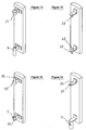
- FIGS 12, 13, 14 and 15 show other equivalent embodiments in which the secondary mast is limited to two fasteners which are attached directly to the antenna.
- Figure 16 is a partial view, in perspective, of another embodiment of the upper attachment means.
- Figure 17 is a detail view of the upper attachment member of the secondary mast.
- Figure 18 shows, in three steps, the use of a temporary guide means.
- Figure 19 is a top view of the guide means.
- the antenna A is fixed on a vertical support mast 1 by two fasteners spaced from each other, respectively upper 2 and lower 6.
- these attachment members are provided on a secondary mast 11 which facilitates the hooking and unhooking maneuvers from a platform B on which is fixed the support mast 1, for example the terrace of a building.
- FIGS. 1 and 2 show schematically the two steps of placing on a support mast 1, an antenna A fixed on a secondary mast 11 which advantageously extends downwards to facilitate maneuvering by an operator who can lift and orient the antenna by means of handles 13,13 'mounted on the lower part of the secondary mast 11 and sufficiently spaced to allow the maneuvering of the mast 11 carrying the antenna A at its upper part.
- the upper attachment member 2 is placed at the upper part of the secondary mast 11, for example towards the middle of the height occupied by the antenna A. It consists, in the embodiment of FIGS. 1 to 6, of an enlarged support piece 21 having, preferably, an outer face 22 of frustoconical shape opening upwards.
- a hooking means 4 which can be constituted, as shown in FIG. 4, of a plate 40 on which are formed a plurality of housings 41 which may each consist of a flange 42 having an inner face having a frustoconical hollow profile, of shape conjugate to that of the support piece 21.
- the plate 40 carries three housings 41 centered on three vertical planes P1, P2, P3 regularly spaced 120 ° ( Figure 4).
- Each flange 42 is provided with a radial slot 43 centered in the corresponding plane P and of a width slightly greater than that of the shaft end 20 on which the frustoconical support piece 21 is mounted and which, in the example shown , constitutes a part of the secondary mast 11 ( Figure 5).
- the secondary mast 11 hooked by the piece 21 to the upper plate 40 is thus suspended vertically along the support mast 1 and is locked in this position by a lower locking means 5 placed in the lower part of the support mast 1 and having two half-flanges 51 clamped to the desired level on the support mast 1 and two half-flanges 52 which are clamped on a lower portion 6 su mast secondary 11 constituting the lower attachment member of the antenna ( Figure 3).
- a kind of snap-fastening of the antenna A has thus been achieved which is attached to the support mast 1 by its upper attachment member 2 while keeping a possibility of rotation about the axis yy 'of the secondary mast 11 for the adjustment in azimuth of the antenna A before blocking the assembly in the selected angular position.
- FIG. 6 shows a variant with an orientable mast, the lower part of which fits into a female base 14 enabling rotation of the mast 1 and its blocking by clamping means 15.
- This function is very useful when the operator does not have access to the antenna from his work station, for example: mast positioned on the bank of a roof, the rotation function makes it possible to bring back the antenna located above the empty on the roof and thus work safely; mast located in a faerie chimney, the rotation makes it possible to bring back the antenna to the right of the door of access ...
- Figure 7 illustrates a second embodiment for allowing the attachment from the ground of at least one secondary mast 11 antenna support A on a vertical support mast.
- the attachment members respectively upper 2 and lower 6 each comprise a pivot 23,61 mounted at the end of an arm 24,62 fixed transversely to the secondary mast 11. These pivots extend towards the low and are aligned so as to be able to engage, after lifting the antenna; in two aligned orifices 44, 54 respectively formed on an upper plate 40 and a lower plate 50 fixed, one at the top and the other at the bottom of the support mast 1.
- the two arms 24,62 After engagement of the pivots 23, 61, the two arms 24,62 respectively support the two trays 40,50 which thus constitute means for hooking and stopping the secondary mast 11 with the antenna A at the desired level.
- the two orifices 44, 54 are aligned along a vertical axis y 'y around which the assembly of the secondary mast 11 and the antenna A can pivot for the azimuth adjustment after snapping of the pivots 23, 61 into the orifices 44, 54 .
- the lower plate 50 carries on the other hand, a series of spaced holes 56 distributed over a circular sector centered on the axis of the orifice 54 and the lower arm 62 is provided with a hole 63 placed at a distance from the pivot 61 equal to the radius of said sector so as to come into coincidence, successively with one of the holes 56 of the series, which allows, after azimuth adjustment, to block the antenna at the desired orientation by introducing into the two aligned holes 63,56, a bolt 64 tightened by a nut.
- the trays 40, 50 each comprise a plurality of orifices 44, 54 centered in radiating planes, for example three planes P1, P2, P3 to allow the introduction of three individually adjustable antennas in azimuth (FIG. 8).
- FIG. 9 illustrates a third embodiment that allows the attachment from the ground of at least one secondary mast 11 for supporting an antenna A on a vertical support mast 1.
- the attachment means (4) located in upper part comprises a latching means 2 and a locking means (5) at the bottom.
- the upper attachment member 2 comprises a rod 25 which is connected to the upper end of the secondary mast 11 by a conical portion 25 '.
- the operator engages this rod 25, by axial sliding, in a housing 45 of shape conjugate to that of the conical portion 25 'and passing through a plate 40 fixed to the upper part of the mast
- the lower end of the secondary mast 11 passes over a lower plate 50 of the support mast 1 and is provided with a conical hole 65 in which the point of a bolt 55 screwed into a threaded bore plateau 50, the assembly constituting the lower attachment member 6 of the secondary mast 11 which can thus pivot with the antenna about the vertical axis passing through the upper rod 25 and the lower hole 65.
- the assembly can be locked in this orientation by screwing the bolt 55 to engage, by axial sliding, the rod 25 in a hole of the same diameter opening at the upper end of the housing 45 in which the conjugate portion 25 'is locked at the end of the mast 11.
- the front end, before orientation and locking, of the upper end of the secondary mast 11 is made by engaging one into the other of a male element and a female element, while retaining a possibility of pivoting for the azimuth adjustment of the antenna.
- the element of the latching device is constituted by a pivot 46 extending upwards and placed at the end of an arm 40 and the secondary mast 11 consists of a tube provided with an opening 26 'placed below a partition 26 in which is formed an axial hole 27.
- the secondary mast 11 By lifting the secondary mast 11 with the antenna, the operator engages the arm 40 'in the opening 26' to place below the wall 26 the pivot 46 which, by letting down the secondary mast 11, engages in the hole 27, the descent movement being stopped by the support of the partition 26 on the arm 40 ', the assembly thus constituting a means of stopping the antenna at the desired level, with the possibility of rotation around the pivot 46 for azimuth adjustment.
- the secondary mast 11 may be locked in the orientation selected for example by a collar 5 of the type shown in Figures 1 to 6.
- the upper attachment means 4 may comprise a plurality of arms 40 'centered in radiating planes P1, P2, P3 for setting up a plurality of individually adjustable antennas.
- the secondary mast 11 is particularly advantageous for attachment and adjustment of the antenna from the ground, but it would also be possible to attach fasteners 2.6 directly to the antenna. of the same type.
- the secondary mast limited to its functional parts is an integral part of the antenna which is snapped directly onto the attachment means 4 of the vertical support mast and is blocked by the locking means 5.
- FIGs 12,13,14,15 thus show attachment members equivalent to those which have been described, respectively, in Figures 1 and 2, 7, 9, 10, the equivalent means bearing the same references.
- FIGS. 1 to 6 may be the subject of a variant shown in FIGS. 16 and 17.
- the support piece 21 formed at the upper part of the secondary mast 11 has only two enlarged portions 21 'with frustoconical faces, which extend in diametrically opposite directions and the flange 42 formed on the upper plate 40 comprises only two frustoconical bearing faces 42 'separated by two recesses 41' diametrically opposite and centered in a radial plane P.
- the operator introduces from below the upper end of the secondary mast 11 into the central orifice of the flange 42, by passing the enlarged portions 21 'in the recesses 41 'to place the support piece 21 above the collar.
- a temporary guiding means as shown in Figure 18 which applies to a device of the type described above comprising an attachment means 4 and a locking means 5 mounted respectively in the upper part and in the lower part of the support mast 1.
- a temporary guide means 7 placed above the locking means 5 and comprising a guide collar 71 fixed to the mast 1 by a clamping member 72, for example two half-flanges in the manner represented , in plan view, in FIG. 19.
- the guide collar 71 is pivotally mounted about an axis 73 on an arm 74 and limits an oblong hole 70 of length slightly greater than the diameter of the secondary mast 11.
- Figure 18 shows, in three steps, the stall of an antenna.
- step (a) the secondary mast 11 carrying the antenna A is fixed along the support mast 1 by the attachment means 4 and the means The guide collar 71 is then closed around the secondary mast 11.
- step (b) the secondary mast 11 has been raised so as to disengage the upper support member 21.
- the locking means 5 has simply been loosened and ensures the maintenance of the lower end of the secondary mast 11 which is also maintained, above, by the guide means 7, being able, however, to tilt to clear the support piece 21, thanks to the degree of freedom given by the longer length of the oblong hole 70.
- Antenna A is therefore not likely to tip on the side or towards the operator, who can make it descend down the mast 1 by sliding in the loose collars of the locking means 5 and the guide means 7.
- the base 14 su mast support 1 can be equipped with a support 16 on which is supported the lower handle 13 'maneuver the secondary mast 11.
- Such a support makes it possible to avoid any deterioration of the sealing lining of the platform.
Landscapes
- Engineering & Computer Science (AREA)
- General Engineering & Computer Science (AREA)
- Computer Networks & Wireless Communication (AREA)
- Mechanical Engineering (AREA)
- Support Of Aerials (AREA)
Applications Claiming Priority (1)
| Application Number | Priority Date | Filing Date | Title |
|---|---|---|---|
| FR0508412A FR2889624B1 (fr) | 2005-08-08 | 2005-08-08 | Mat encliquetable support d'antennes de radio communication |
Publications (1)
| Publication Number | Publication Date |
|---|---|
| EP1753075A1 true EP1753075A1 (de) | 2007-02-14 |
Family
ID=36149061
Family Applications (1)
| Application Number | Title | Priority Date | Filing Date |
|---|---|---|---|
| EP06291273A Withdrawn EP1753075A1 (de) | 2005-08-08 | 2006-08-07 | Mast mit Schnellbefestigung für Funkkommunikationsantennen |
Country Status (2)
| Country | Link |
|---|---|
| EP (1) | EP1753075A1 (de) |
| FR (1) | FR2889624B1 (de) |
Cited By (13)
| Publication number | Priority date | Publication date | Assignee | Title |
|---|---|---|---|---|
| AT503466B1 (de) * | 2006-03-16 | 2009-02-15 | Kremsmueller Industrieanlagenb | Traganordnung für sektorantennen |
| ITVR20090117A1 (it) * | 2009-07-30 | 2011-01-31 | Mastec S R L | Porta antenna |
| GB2474605A (en) * | 2009-10-09 | 2011-04-20 | Fasmetrics Ltd | Antenna mast system and mounting apparatus |
| WO2011127988A1 (en) * | 2010-04-14 | 2011-10-20 | Telefonaktiebolaget L M Ericsson (Publ) | An antenna attachment arrangement, a module comprising such an arrangement and an antenna mast arrangement |
| GB2480168A (en) * | 2009-10-09 | 2011-11-09 | Fasmetrics Ltd | Antenna mast system and mounting apparatus |
| US9728849B2 (en) | 2011-07-15 | 2017-08-08 | Fasmetrics S.A. | Antenna alignment apparatus and method |
| US9893410B2 (en) | 2012-05-18 | 2018-02-13 | Fasmetrics S.A. | Apparatus and method for accurate and precise positioning of cellular antennas |
| CN110274375A (zh) * | 2019-07-18 | 2019-09-24 | 宁波奥克斯电气股份有限公司 | 一种管路固定块、空调器室外机及空调器 |
| CN114300825A (zh) * | 2021-12-29 | 2022-04-08 | 中国电信股份有限公司 | 一种室内通信装置 |
| GB2579977B (en) * | 2017-08-15 | 2022-07-20 | Commscope Design & Integration Uk Ltd | Antenna mounting bracket assembly |
| CN115663451A (zh) * | 2022-11-30 | 2023-01-31 | 武汉船舶通信研究所(中国船舶重工集团公司第七二二研究所) | 一种用于天线上绝缘子的导向式安装方法 |
| CN117937091A (zh) * | 2024-03-11 | 2024-04-26 | 深圳市雅诺讯科技有限公司 | 一种高集成ntn空天地自适应mimo天线 |
| WO2026045726A1 (zh) * | 2024-08-29 | 2026-03-05 | 深圳汉阳科技有限公司 | 一种天线立杆及定位基站 |
Families Citing this family (1)
| Publication number | Priority date | Publication date | Assignee | Title |
|---|---|---|---|---|
| CN109216869B (zh) * | 2018-09-21 | 2024-04-30 | 中电科海洋信息技术研究院有限公司 | 用于固定gps天线的固定装置 |
Citations (5)
| Publication number | Priority date | Publication date | Assignee | Title |
|---|---|---|---|---|
| FR2558203A3 (fr) * | 1982-09-29 | 1985-07-19 | Garami Eugene | Porte-battants reglable |
| FR2733633A1 (fr) * | 1995-04-28 | 1996-10-31 | Telecommunications Internation | Dispositif d'orientation en azimut d'antennes directionnelles |
| US5620272A (en) * | 1995-05-10 | 1997-04-15 | Sheng; Chim-Yuem | Adjustable joint assembly for ladder sections |
| FR2815477A1 (fr) * | 2000-10-16 | 2002-04-19 | Bouygues Telecom Sa | Supports pour la fixation sur un mat d'une ou plusieurs antennes relais de systemes de radio-telecommunication cellulaire et dispositi pour le reglage de l'orientation d'une telle antenne |
| FR2818810A1 (fr) * | 2000-12-22 | 2002-06-28 | Coprebat | Support antenne radio reglable du bas |
-
2005
- 2005-08-08 FR FR0508412A patent/FR2889624B1/fr not_active Expired - Fee Related
-
2006
- 2006-08-07 EP EP06291273A patent/EP1753075A1/de not_active Withdrawn
Patent Citations (5)
| Publication number | Priority date | Publication date | Assignee | Title |
|---|---|---|---|---|
| FR2558203A3 (fr) * | 1982-09-29 | 1985-07-19 | Garami Eugene | Porte-battants reglable |
| FR2733633A1 (fr) * | 1995-04-28 | 1996-10-31 | Telecommunications Internation | Dispositif d'orientation en azimut d'antennes directionnelles |
| US5620272A (en) * | 1995-05-10 | 1997-04-15 | Sheng; Chim-Yuem | Adjustable joint assembly for ladder sections |
| FR2815477A1 (fr) * | 2000-10-16 | 2002-04-19 | Bouygues Telecom Sa | Supports pour la fixation sur un mat d'une ou plusieurs antennes relais de systemes de radio-telecommunication cellulaire et dispositi pour le reglage de l'orientation d'une telle antenne |
| FR2818810A1 (fr) * | 2000-12-22 | 2002-06-28 | Coprebat | Support antenne radio reglable du bas |
Cited By (19)
| Publication number | Priority date | Publication date | Assignee | Title |
|---|---|---|---|---|
| AT503466B1 (de) * | 2006-03-16 | 2009-02-15 | Kremsmueller Industrieanlagenb | Traganordnung für sektorantennen |
| ITVR20090117A1 (it) * | 2009-07-30 | 2011-01-31 | Mastec S R L | Porta antenna |
| EP2486623B1 (de) * | 2009-10-09 | 2020-07-01 | Fasmetrics S.A. | Antennenmastsystem und montagevorrichtung |
| GB2474605A (en) * | 2009-10-09 | 2011-04-20 | Fasmetrics Ltd | Antenna mast system and mounting apparatus |
| GB2474605B (en) * | 2009-10-09 | 2011-09-07 | Fasmetrics Ltd | Antenna mast system and mounting apparatus |
| GB2480168A (en) * | 2009-10-09 | 2011-11-09 | Fasmetrics Ltd | Antenna mast system and mounting apparatus |
| GB2480168B (en) * | 2009-10-09 | 2011-12-28 | Fasmetrics Ltd | Antenna mast system and mounting apparatus |
| WO2011127988A1 (en) * | 2010-04-14 | 2011-10-20 | Telefonaktiebolaget L M Ericsson (Publ) | An antenna attachment arrangement, a module comprising such an arrangement and an antenna mast arrangement |
| US8599096B2 (en) | 2010-04-14 | 2013-12-03 | Telefonaktiebolaget L M Ericsson (Publ) | Antenna attachment arrangement, a module comprising such an arrangement and an antenna mast arrangement |
| US9728849B2 (en) | 2011-07-15 | 2017-08-08 | Fasmetrics S.A. | Antenna alignment apparatus and method |
| US9893410B2 (en) | 2012-05-18 | 2018-02-13 | Fasmetrics S.A. | Apparatus and method for accurate and precise positioning of cellular antennas |
| US10686243B2 (en) | 2012-05-18 | 2020-06-16 | Fasmetrics S.A. | Apparatus and method for accurate and precise positioning of cellular antennas |
| GB2579977B (en) * | 2017-08-15 | 2022-07-20 | Commscope Design & Integration Uk Ltd | Antenna mounting bracket assembly |
| CN110274375A (zh) * | 2019-07-18 | 2019-09-24 | 宁波奥克斯电气股份有限公司 | 一种管路固定块、空调器室外机及空调器 |
| CN114300825A (zh) * | 2021-12-29 | 2022-04-08 | 中国电信股份有限公司 | 一种室内通信装置 |
| CN115663451A (zh) * | 2022-11-30 | 2023-01-31 | 武汉船舶通信研究所(中国船舶重工集团公司第七二二研究所) | 一种用于天线上绝缘子的导向式安装方法 |
| CN115663451B (zh) * | 2022-11-30 | 2024-05-17 | 武汉船舶通信研究所(中国船舶重工集团公司第七二二研究所) | 一种用于天线上绝缘子的导向式安装方法 |
| CN117937091A (zh) * | 2024-03-11 | 2024-04-26 | 深圳市雅诺讯科技有限公司 | 一种高集成ntn空天地自适应mimo天线 |
| WO2026045726A1 (zh) * | 2024-08-29 | 2026-03-05 | 深圳汉阳科技有限公司 | 一种天线立杆及定位基站 |
Also Published As
| Publication number | Publication date |
|---|---|
| FR2889624B1 (fr) | 2009-10-30 |
| FR2889624A1 (fr) | 2007-02-09 |
Similar Documents
| Publication | Publication Date | Title |
|---|---|---|
| EP1753075A1 (de) | Mast mit Schnellbefestigung für Funkkommunikationsantennen | |
| EP3278930B1 (de) | Vorrichtung zum einsetzen oder herausnehmen einer glasscheibe eines kraftfahrzeugs | |
| WO2001082406A1 (fr) | Mats d'antennes relais de systeme de radio-telecommunication cellulaire | |
| EP2469643A1 (de) | Eigenstabiler Mast für Terrasse, und Montageverfahren dieses Masts | |
| EP0132205A1 (de) | Aufstellvorrichtung für Masten | |
| EP0099298B1 (de) | Befestigungsvorrichtung für ein Gebäude und Anwendung bei dem Aufbau von Gerüsten | |
| CA2402256A1 (fr) | Dispositif de diffusion hertzienne et pylone pour un tel dispositif | |
| FR2898180A1 (fr) | Dispositif orientable de suspension d'appareillage | |
| FR2745423A1 (fr) | Support d'antenne | |
| EP1050919A1 (de) | Befestigungs- und Einstellungsvorrichtung für eine Antenne | |
| EP1932983A1 (de) | Halterungseinheit für ein Dachelement, Unterstand, der eine solche Halterungseinheit umfasst und Montageverfahren eines solchen Unterstands | |
| EP3700006B1 (de) | Mehrzweckvorrichtung zur montage einer apparatur auf eine plattform | |
| FR2824956A1 (fr) | Support d'antennes securise | |
| EP2609265B1 (de) | Automatisierter zerlegbarer kippmast mit werkzeuglos montierbaren elementen | |
| FR2685723A1 (fr) | Dispositif de stabilisation pour des panneaux de coffrage. | |
| FR3125504A1 (fr) | Procédé pour le montage ou le démontage d’une pale sur une éolienne en mer et plateforme équipée pour la mise en œuvre d’un tel procédé. | |
| FR2778193A1 (fr) | Dispositif de passerelles transportables de protection, monte sur un appareil de levage | |
| FR2850695A1 (fr) | Mat support d'antenne rabattable | |
| FR2791182A1 (fr) | Embase servant a la mise en place d'une antenne sur une paroi verticale, notamment sur la facade d'un immeuble | |
| FR2891406A1 (fr) | Dispositif support d'un appareillage specialement adapte pour les antennes de radio communication. | |
| FR3092895A1 (fr) | Dispositif de suspension d'un appareillage a partir d'une plateforme | |
| FR2956424A1 (fr) | Plateforme de travail en encorbellement | |
| FR2682977A1 (fr) | Dispositif de stabilisation pour des panneaux de coffrage. | |
| EP1403961B1 (de) | Mast für Funkvorrichtung | |
| FR2780816A1 (fr) | Dispositif support d'antenne pour equipement assurant une liaison radioelectrique entre au moins un telephone portable et un reseau telephonique |
Legal Events
| Date | Code | Title | Description |
|---|---|---|---|
| PUAI | Public reference made under article 153(3) epc to a published international application that has entered the european phase |
Free format text: ORIGINAL CODE: 0009012 |
|
| AK | Designated contracting states |
Kind code of ref document: A1 Designated state(s): AT BE BG CH CY CZ DE DK EE ES FI FR GB GR HU IE IS IT LI LT LU LV MC NL PL PT RO SE SI SK TR |
|
| AX | Request for extension of the european patent |
Extension state: AL BA HR MK YU |
|
| AKX | Designation fees paid | ||
| REG | Reference to a national code |
Ref country code: DE Ref legal event code: 8566 |
|
| STAA | Information on the status of an ep patent application or granted ep patent |
Free format text: STATUS: THE APPLICATION IS DEEMED TO BE WITHDRAWN |
|
| 18D | Application deemed to be withdrawn |
Effective date: 20070815 |