EP1753111A2 - Monolithisch Alternatorspannungsregler mit konfigurierbares Regulierungsmodus - Google Patents
Monolithisch Alternatorspannungsregler mit konfigurierbares Regulierungsmodus Download PDFInfo
- Publication number
- EP1753111A2 EP1753111A2 EP06016533A EP06016533A EP1753111A2 EP 1753111 A2 EP1753111 A2 EP 1753111A2 EP 06016533 A EP06016533 A EP 06016533A EP 06016533 A EP06016533 A EP 06016533A EP 1753111 A2 EP1753111 A2 EP 1753111A2
- Authority
- EP
- European Patent Office
- Prior art keywords
- circuit
- alternator
- integrated circuit
- mode
- stand
- Prior art date
- Legal status (The legal status is an assumption and is not a legal conclusion. Google has not performed a legal analysis and makes no representation as to the accuracy of the status listed.)
- Withdrawn
Links
Images



Classifications
-
- H—ELECTRICITY
- H02—GENERATION; CONVERSION OR DISTRIBUTION OF ELECTRIC POWER
- H02J—ELECTRIC POWER NETWORKS; CIRCUIT ARRANGEMENTS OR SYSTEMS FOR SUPPLYING OR DISTRIBUTING ELECTRIC POWER; SYSTEMS FOR STORING ELECTRIC ENERGY
- H02J7/00—Circuit arrangements for charging or discharging batteries or for supplying loads from batteries
- H02J7/14—Circuit arrangements for charging or discharging batteries or for supplying loads from batteries for charging batteries from dynamo-electric generators driven at varying speed, e.g. on vehicle
- H02J7/16—Regulation of the charging current or voltage by variation of field
- H02J7/24—Regulation of the charging current or voltage by variation of field using discharge tubes or semiconductor devices
Definitions
- the present invention relates to an alternator regulator and more particularly to an alternator regulator that can be configured to operate in configurable regulation modes.
- Automotive alternator regulators incorporate several requirements and features that are customized for specific applications. Because of the high cost and concerns about robustness of a more flexible solution, such as a microprocessor design, the design architecture of the automotive alternator regulators typically utilizes an Application Specific Integrated Circuit (ASIC).
- ASIC Application Specific Integrated Circuit
- the integrated circuit includes a first circuit for performing core regulation functions; a second circuit having a mask selectable operation circuit that allows the integrated circuit to select an operational mode thereof, the mode being selectable from one of a stand-alone mode, a remote controlled mode wherein the first circuit is controlled by an external circuit, and a combination of the stand-alone mode and the remote controlled mode; and a third circuit having an output driver circuit for controlling a field winding of the alternator circuit.
- An alternator regulator capable of operation in configurable modes is also disclosed.
- Figure 1 is a diagram of the architecture of an ASIC Alternator Regulator Charging System in accordance with one embodiment of the present invention
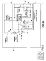
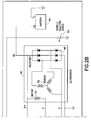
- Figure 2 is a system level integration diagram of a stand-alone Alternator Regulator Charging System design in accordance with one embodiment of the present invention
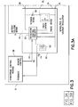
- Figure 3 is a system level integration diagram of a remote controlled Alternator Regulator Charging System design in accordance with one embodiment of the present invention.
- Figure 4 shows a combination stand-alone and remote controlled system.
- a feature set for an Application Specific Integrated Circuit is determined.
- the invention provides a method of incorporation of the feature set into a monolithic ASIC that could be used for stand-alone, remotely controlled, and combinational designs for automotive charging system applications.
- Core ASIC architecture is determined such that specific system interface pins are shared and provide the necessary flexibility, while limiting the cost of the IC by eliminating excess Input/Output connections.
- FIG. 1 shows a monolithic ASIC 10 designed and used for an Alternator Regulator Charging System in accordance with the present invention.
- the ASIC 10 includes regulation control circuitry and a plurality of pins for providing and receiving input and output signals.
- monolithic ASIC 10 comprises a regulation control circuit 20 for performing monolithic ASIC core regulation functions.
- the circuit 20 receives battery voltage sense signal from pin 22 and alternator winding phase voltage sense signal from pin 24.
- the monolithic ASIC 10 further comprises a circuit 12 for performing a mask selectable operation.
- circuit 12 When the monolithic ASIC 10 is used in a stand-alone Alternator Regulator Charging System, circuit 12 is provided with an ignition/activation signal at pin 16 from the automotive ignition switch. However, when the monolithic ASIC 10 is used in a remote-control Alternator Regulator Charging System, circuit 12 will provide a feedback output signal to pin 14, and receives remote control signals at pin 18.
- the remote control interface may comprise a two line PWM interface (chassis ground being the second line) that provides asynchronous communication between the PCM and the ASIC. Other features include 0mV/°C temperature compensation, and optionally RC input command for Z-curve mode.
- line 16 provides ignition line power-up to the ASIC.
- other features include -10mV/° C temperature compensation, z curve temperature compensation and lamp driver capability for charging fault indication.
- the monolithic ASIC 10 comprises a circuit 26 that includes a flyback diode for the field winding current when the regulator output driver switch is turned off. The cathode of the flyback diode is connected to the alternator voltage sense at pin 28.
- the monolithic ASIC 10 comprises an output driver circuit 30 that includes the regulator output field driver switch. The drain and source of the switch, if a FET, are connected between the anode of the diode of circuit 26 and the ground at pin 34. The gate of the field driver switch is controlled by the core circuit 20. The field driver switch controls the alternator field winding via pin 32.
- FIG. 2 shows a stand-alone Alternator Regulator Charging System 8.
- the stand-alone Alternator Regulator Charging System 8 includes the monolithic ASIC voltage regulator 10, an alternator circuit 40, a battery 44, an ignition switch 50, a charging fault indicator 52 such as a lamp, and vehicle electric loads 54.
- the alternator circuit 40 includes alternator field rotor 41, a three phase stator 42, and a three phase full wave diode rectifier bridge 48.
- the alternator circuit 40 is coupled to a battery 44 via the cathode terminals of the six diode rectifier 48 and to the ground via the anode terminals. It is further connected to the monolithic ASIC 10, wherein the rotor 41 is parallel connected to the flyback diode 56 at pins 28 and 32 and a stator 42 winding is connected to pin 24 to provide a phase voltage sense.
- the monolithic ASIC 10 is further shown to include a lamp driver switch 46 for driving the charging fault indicator 52.
- Switch 56 can optionally provide a feedback signal on the state of the charging system to the PCM via FB pin 14, even in the stand-alone system.
- Figure 3 shows a remote-controlled Alternator Regulator Charging System 6.
- the remote-controlled Alternator Regulator Charging System 6 includes the monolithic ASIC voltage regulator 10, an alternator circuit 40, a battery 44, and vehicle electric loads 54.
- the powertrain control module 58 which receives feedback from pin 14, the feedback being provided by the circuit 20, and provides remote control signals via PWM to pin 18 to control the regulator.
- the alternator circuit 40 includes a field rotor 41, a three phase stator 42, and a six diode rectifier bridge 48.
- the alternator circuit 40 is coupled to a battery 44 via the cathode terminals of the six diode rectifier 48 and to the ground via the anode terminals. It is further connected to the monolithic ASIC 10, wherein the rotor winding 41 is parallel connected to the flyback diode at pins 28 and 32 and a stator 42 winding is connected to pin 24 to provide a phase voltage sense.
- the remote-controlled Alternator Regulator Charging System 6 does not include a charging indicator, so the lamp driver 46 of Figure 2 is not used.
- the powertrain control module 58 receives the feedback signal 14 regarding charging system operation and generates remote control signals 18 to control regulation.
- Figure 4 shows a combinational Alternator Regulator Charging System 6, which can be used in both a stand-alone mode and in a remote controlled mode.
- the remote-controlled Alternator Regulator Charging System 6 includes the monolithic ASIC voltage regulator 10, an alternator circuit 40, a battery 44, and vehicle electric loads 54.
- the powertrain control module 58 which receives feedback from pin 14, the feedback being provided by the circuit 20, and provides remote control signals via PWM to pin 18 to control the regulator.
- the alternator circuit 40 includes a field rotor 41, a three phase stator 42, and a six diode rectifier bridge 48.
- the alternator circuit 40 is coupled to a battery 44 via the cathode terminals of the six diode rectifier 48 and to the ground via the anode terminals. It is further connected to the monolithic ASIC 10, wherein the rotor winding 41 is parallel connected to the flyback diode at pins 28 and 32 and a stator 42 winding is connected to pin 24 to provide a phase voltage sense.
- the combination Alternator Regulator Charging System 6 includes an ignition switch 50, a charging fault indicator 52, and a lamp driver 46. Also included is a powertrain control module 58 that receives, through switch 56, feedback signals 14 regarding the charging system's operation and generates remote control signals 18 to control regulation.
- Table 1 illustrates an example of three feature set implementations achievable in a single monolithic ASIC.
- An integrated circuit for controlling an alternator circuit in an alternator regulator charging system includes a first circuit for performing core regulation functions; a second circuit having a mask selectable operation circuit that allows the integrated circuit to select an operational mode thereof, the mode being selectable from one of a stand-alone mode, a remote controlled mode wherein the first circuit is controlled by an external circuit, and a combination of the stand-alone mode and the remote controlled mode; and a third circuit having an output driver circuit for controlling a field winding of the alternator circuit.
Landscapes
- Engineering & Computer Science (AREA)
- Power Engineering (AREA)
- Control Of Eletrric Generators (AREA)
- Control Of Charge By Means Of Generators (AREA)
- Charge And Discharge Circuits For Batteries Or The Like (AREA)
Applications Claiming Priority (2)
| Application Number | Priority Date | Filing Date | Title |
|---|---|---|---|
| US70649805P | 2005-08-08 | 2005-08-08 | |
| US11/462,060 US7521903B2 (en) | 2005-08-08 | 2006-08-03 | Monolithic alternator regulator with configurable regulation modes |
Publications (2)
| Publication Number | Publication Date |
|---|---|
| EP1753111A2 true EP1753111A2 (de) | 2007-02-14 |
| EP1753111A3 EP1753111A3 (de) | 2010-06-09 |
Family
ID=37101889
Family Applications (1)
| Application Number | Title | Priority Date | Filing Date |
|---|---|---|---|
| EP06016533A Withdrawn EP1753111A3 (de) | 2005-08-08 | 2006-08-08 | Monolithisch Alternatorspannungsregler mit konfigurierbares Regulierungsmodus |
Country Status (3)
| Country | Link |
|---|---|
| US (1) | US7521903B2 (de) |
| EP (1) | EP1753111A3 (de) |
| JP (1) | JP2007053897A (de) |
Cited By (1)
| Publication number | Priority date | Publication date | Assignee | Title |
|---|---|---|---|---|
| DE102007060222B4 (de) | 2007-12-14 | 2024-08-01 | Seg Automotive Germany Gmbh | Generatorvorrichtung mit Stromableitelementen |
Families Citing this family (8)
| Publication number | Priority date | Publication date | Assignee | Title |
|---|---|---|---|---|
| US20090283389A1 (en) * | 2008-05-16 | 2009-11-19 | Tyco Electronics Brasil Ltda | Battery saving circuit |
| FR2949914B1 (fr) * | 2009-09-07 | 2014-11-21 | Valeo Equip Electr Moteur | Alternateur a redressement synchrone pour vehicule automobile, equipe de moyens electroniques de gestion de defauts |
| US10268805B2 (en) * | 2010-01-26 | 2019-04-23 | At&T Intellectual Property I, L.P. | System and method for providing multimedia digital rights transfer |
| US8773080B2 (en) * | 2010-12-16 | 2014-07-08 | Kohler Co. | Resonant commutation system for exciting a three-phase alternator |
| US8836292B1 (en) * | 2011-04-15 | 2014-09-16 | Kevin Mark Klughart | Electric power generation system and method |
| WO2013142493A1 (en) | 2012-03-19 | 2013-09-26 | Mayo Foundation For Medical Education And Research | Analyzing and answering questions |
| WO2013166267A1 (en) | 2012-05-02 | 2013-11-07 | Remy Technologies, Llc | Alternator with lockout mode |
| FR3030152B1 (fr) * | 2014-12-15 | 2018-10-12 | Valeo Equipements Electriques Moteur | Procede de controle d'un dispositif de regulation d'un alternateur de vehicule automobile, dispositif de regulation et alternateur correspondants |
Family Cites Families (16)
| Publication number | Priority date | Publication date | Assignee | Title |
|---|---|---|---|---|
| DE2610137A1 (de) * | 1976-03-11 | 1977-09-29 | Bosch Gmbh Robert | Generator mit freilaufdiode und spannungsregler |
| JP2793303B2 (ja) * | 1989-12-16 | 1998-09-03 | ダイハツ工業株式会社 | オルタネータの制御方法 |
| JP3256260B2 (ja) * | 1992-03-10 | 2002-02-12 | ダイハツ工業株式会社 | アイドル回転数制御のためのオルタネータの発電仕事量検出方法 |
| US5734255A (en) * | 1996-03-13 | 1998-03-31 | Alaska Power Systems Inc. | Control system and circuits for distributed electrical power generating stations |
| US6137247A (en) * | 1997-12-08 | 2000-10-24 | Denso Corporation | Electric power generation control for vehicles using a plurality of control signals |
| JP2000092754A (ja) * | 1998-09-14 | 2000-03-31 | Toshiba Corp | 電気機器の電源回路 |
| US6215277B1 (en) * | 2000-02-17 | 2001-04-10 | Ford Global Tech. Inc | Electrical charging system |
| KR100376131B1 (ko) * | 2000-09-22 | 2003-03-15 | 삼성전자주식회사 | 대기전원 절전형 전원장치 및 그 제어방법 |
| JP4314751B2 (ja) * | 2001-04-16 | 2009-08-19 | 株式会社デンソー | 充電システムおよび車両用発電制御装置 |
| JP2003033092A (ja) | 2001-07-18 | 2003-01-31 | Mitsubishi Electric Corp | 車両用発電機の制御装置 |
| US6670792B1 (en) * | 2001-09-07 | 2003-12-30 | International Rectifier Corporation | Alternator regulation circuit having parallel field coil current re-circulation |
| US6573689B1 (en) * | 2001-09-28 | 2003-06-03 | International Rectifier Corporation | Programmable alternator regulation circuitry |
| JP2003224935A (ja) * | 2002-01-29 | 2003-08-08 | Fuji Heavy Ind Ltd | 車両用発電機の発電制御装置 |
| EP1401081A3 (de) * | 2002-09-17 | 2008-02-13 | International Rectifier Corporation | Intelligentes Spannungsregelsystem in einem Kraftfahrzeug |
| WO2005050332A2 (en) * | 2003-11-17 | 2005-06-02 | Ballard Commercial Industries, Inc. | Improved regulator system for alternator |
| JP4232693B2 (ja) * | 2004-06-08 | 2009-03-04 | 株式会社デンソー | 車両用発電制御システム |
-
2006
- 2006-08-03 US US11/462,060 patent/US7521903B2/en not_active Expired - Fee Related
- 2006-08-08 EP EP06016533A patent/EP1753111A3/de not_active Withdrawn
- 2006-08-08 JP JP2006215271A patent/JP2007053897A/ja not_active Ceased
Cited By (1)
| Publication number | Priority date | Publication date | Assignee | Title |
|---|---|---|---|---|
| DE102007060222B4 (de) | 2007-12-14 | 2024-08-01 | Seg Automotive Germany Gmbh | Generatorvorrichtung mit Stromableitelementen |
Also Published As
| Publication number | Publication date |
|---|---|
| JP2007053897A (ja) | 2007-03-01 |
| US20070029978A1 (en) | 2007-02-08 |
| EP1753111A3 (de) | 2010-06-09 |
| US7521903B2 (en) | 2009-04-21 |
Similar Documents
| Publication | Publication Date | Title |
|---|---|---|
| US5889392A (en) | Switch-mode regulators and methods providing transient response speed-up | |
| EP2083497B1 (de) | Elektronisches Steuersystem und Netzteil des Systems | |
| US7129681B2 (en) | Power supply apparatus having parallel connected switching and series regulators and method of operation | |
| US7586296B2 (en) | Power supply apparatus | |
| US20050110469A1 (en) | Power supply circuit | |
| EP1411406B1 (de) | Spannungsversorgung mit mehreren Versorgungspannungen | |
| CN101164220B (zh) | 电源控制方法及其结构 | |
| US7274577B2 (en) | Electronic instrument having booster circuit | |
| EP1753111A2 (de) | Monolithisch Alternatorspannungsregler mit konfigurierbares Regulierungsmodus | |
| JP2008511277A (ja) | 過電圧保護を行う電圧制御器 | |
| EP1879284B1 (de) | DC-DC-Wandler und Netzteilvorrichtung | |
| US6028373A (en) | Power supply distributed load startup system | |
| CN108649663A (zh) | 限压供电电路及电子设备 | |
| EP0911941A2 (de) | Stromversorgungseinheit für Fahrzeuge | |
| EP1209792A2 (de) | Spannungssteuerung für Kraftfahrzeugwechselstromgenerator | |
| EP1215797A2 (de) | Automatischestromabgriffgesteuerte Ausgangsschaltung mit Speicherspannungsbelestung oder gegenelektromotorische Kraft aufweissender Belastung | |
| EP1848101A1 (de) | Stromversorgungsschaltung und tragbare vorrichtung | |
| CN101238637B (zh) | 控制外部半桥功率输出级的电子控制单元和具有电子控制单元的电动驱动装置 | |
| JP2007053897A5 (de) | ||
| US20200161983A1 (en) | Power converter and power converter control method | |
| US20130021020A1 (en) | Power source monitoring device, lens barrel, camera, and power source monitoring method | |
| US12015342B2 (en) | DC-DC converter and method for operating a DC-DC converter | |
| KR100682034B1 (ko) | 충전 겸용 자동전압조정기 | |
| CN223514791U (zh) | 一种可欠压保护下强制启动的Boost升压电路 | |
| JP3123869B2 (ja) | 直流分巻電動機の制御装置 |
Legal Events
| Date | Code | Title | Description |
|---|---|---|---|
| PUAI | Public reference made under article 153(3) epc to a published international application that has entered the european phase |
Free format text: ORIGINAL CODE: 0009012 |
|
| 17P | Request for examination filed |
Effective date: 20060808 |
|
| AK | Designated contracting states |
Kind code of ref document: A2 Designated state(s): AT BE BG CH CY CZ DE DK EE ES FI FR GB GR HU IE IS IT LI LT LU LV MC NL PL PT RO SE SI SK TR |
|
| AX | Request for extension of the european patent |
Extension state: AL BA HR MK YU |
|
| RIN1 | Information on inventor provided before grant (corrected) |
Inventor name: MERSMANN, ANDREAS Inventor name: GRABOWSKI, FRANZ Inventor name: SOMMERFELD, PETER Inventor name: RENEHAN, JOHN |
|
| RAP1 | Party data changed (applicant data changed or rights of an application transferred) |
Owner name: SILICONIX TECHNOLOGY C.V. |
|
| PUAL | Search report despatched |
Free format text: ORIGINAL CODE: 0009013 |
|
| STAA | Information on the status of an ep patent application or granted ep patent |
Free format text: STATUS: THE APPLICATION HAS BEEN WITHDRAWN |
|
| AK | Designated contracting states |
Kind code of ref document: A3 Designated state(s): AT BE BG CH CY CZ DE DK EE ES FI FR GB GR HU IE IS IT LI LT LU LV MC NL PL PT RO SE SI SK TR |
|
| AX | Request for extension of the european patent |
Extension state: AL BA HR MK RS |
|
| 18W | Application withdrawn |
Effective date: 20100528 |