EP1753272A2 - Circuit convertisseur comprenant une inductance au lieu d' un transformateur, pour l' alimentation pulsée d' une lampe à barrière diélectrique. - Google Patents
Circuit convertisseur comprenant une inductance au lieu d' un transformateur, pour l' alimentation pulsée d' une lampe à barrière diélectrique. Download PDFInfo
- Publication number
- EP1753272A2 EP1753272A2 EP06014622A EP06014622A EP1753272A2 EP 1753272 A2 EP1753272 A2 EP 1753272A2 EP 06014622 A EP06014622 A EP 06014622A EP 06014622 A EP06014622 A EP 06014622A EP 1753272 A2 EP1753272 A2 EP 1753272A2
- Authority
- EP
- European Patent Office
- Prior art keywords
- circuit arrangement
- discharge lamp
- switch
- arrangement according
- circuit
- Prior art date
- Legal status (The legal status is an assumption and is not a legal conclusion. Google has not performed a legal analysis and makes no representation as to the accuracy of the status listed.)
- Withdrawn
Links
- 230000004888 barrier function Effects 0.000 title claims description 34
- 238000000034 method Methods 0.000 claims abstract description 5
- 239000003990 capacitor Substances 0.000 claims description 11
- 230000001360 synchronised effect Effects 0.000 claims 2
- 238000010586 diagram Methods 0.000 description 6
- 230000000903 blocking effect Effects 0.000 description 3
- 230000005669 field effect Effects 0.000 description 3
- 230000010355 oscillation Effects 0.000 description 3
- HBMJWWWQQXIZIP-UHFFFAOYSA-N silicon carbide Chemical compound [Si+]#[C-] HBMJWWWQQXIZIP-UHFFFAOYSA-N 0.000 description 3
- 229910010271 silicon carbide Inorganic materials 0.000 description 3
- 238000006073 displacement reaction Methods 0.000 description 2
- 238000005516 engineering process Methods 0.000 description 2
- 230000001965 increasing effect Effects 0.000 description 2
- 230000001939 inductive effect Effects 0.000 description 2
- 239000004065 semiconductor Substances 0.000 description 2
- 238000010276 construction Methods 0.000 description 1
- 230000001419 dependent effect Effects 0.000 description 1
- 230000000694 effects Effects 0.000 description 1
- 238000012432 intermediate storage Methods 0.000 description 1
- 229910044991 metal oxide Inorganic materials 0.000 description 1
- 150000004706 metal oxides Chemical class 0.000 description 1
- 238000001208 nuclear magnetic resonance pulse sequence Methods 0.000 description 1
- 238000011017 operating method Methods 0.000 description 1
- 238000011084 recovery Methods 0.000 description 1
- 230000000630 rising effect Effects 0.000 description 1
- 238000001228 spectrum Methods 0.000 description 1
Images



Classifications
-
- H—ELECTRICITY
- H05—ELECTRIC TECHNIQUES NOT OTHERWISE PROVIDED FOR
- H05B—ELECTRIC HEATING; ELECTRIC LIGHT SOURCES NOT OTHERWISE PROVIDED FOR; CIRCUIT ARRANGEMENTS FOR ELECTRIC LIGHT SOURCES, IN GENERAL
- H05B41/00—Circuit arrangements or apparatus for igniting or operating discharge lamps
- H05B41/14—Circuit arrangements
- H05B41/26—Circuit arrangements in which the lamp is fed by power derived from DC by means of a converter, e.g. by high-voltage DC
- H05B41/28—Circuit arrangements in which the lamp is fed by power derived from DC by means of a converter, e.g. by high-voltage DC using static converters
- H05B41/2806—Circuit arrangements in which the lamp is fed by power derived from DC by means of a converter, e.g. by high-voltage DC using static converters with semiconductor devices and specially adapted for lamps without electrodes in the vessel, e.g. surface discharge lamps, electrodeless discharge lamps
-
- H—ELECTRICITY
- H05—ELECTRIC TECHNIQUES NOT OTHERWISE PROVIDED FOR
- H05B—ELECTRIC HEATING; ELECTRIC LIGHT SOURCES NOT OTHERWISE PROVIDED FOR; CIRCUIT ARRANGEMENTS FOR ELECTRIC LIGHT SOURCES, IN GENERAL
- H05B41/00—Circuit arrangements or apparatus for igniting or operating discharge lamps
- H05B41/14—Circuit arrangements
- H05B41/30—Circuit arrangements in which the lamp is fed by pulses, e.g. flash lamp
-
- H—ELECTRICITY
- H05—ELECTRIC TECHNIQUES NOT OTHERWISE PROVIDED FOR
- H05B—ELECTRIC HEATING; ELECTRIC LIGHT SOURCES NOT OTHERWISE PROVIDED FOR; CIRCUIT ARRANGEMENTS FOR ELECTRIC LIGHT SOURCES, IN GENERAL
- H05B41/00—Circuit arrangements or apparatus for igniting or operating discharge lamps
- H05B41/14—Circuit arrangements
-
- H—ELECTRICITY
- H05—ELECTRIC TECHNIQUES NOT OTHERWISE PROVIDED FOR
- H05B—ELECTRIC HEATING; ELECTRIC LIGHT SOURCES NOT OTHERWISE PROVIDED FOR; CIRCUIT ARRANGEMENTS FOR ELECTRIC LIGHT SOURCES, IN GENERAL
- H05B41/00—Circuit arrangements or apparatus for igniting or operating discharge lamps
- H05B41/14—Circuit arrangements
- H05B41/26—Circuit arrangements in which the lamp is fed by power derived from DC by means of a converter, e.g. by high-voltage DC
-
- Y—GENERAL TAGGING OF NEW TECHNOLOGICAL DEVELOPMENTS; GENERAL TAGGING OF CROSS-SECTIONAL TECHNOLOGIES SPANNING OVER SEVERAL SECTIONS OF THE IPC; TECHNICAL SUBJECTS COVERED BY FORMER USPC CROSS-REFERENCE ART COLLECTIONS [XRACs] AND DIGESTS
- Y02—TECHNOLOGIES OR APPLICATIONS FOR MITIGATION OR ADAPTATION AGAINST CLIMATE CHANGE
- Y02B—CLIMATE CHANGE MITIGATION TECHNOLOGIES RELATED TO BUILDINGS, e.g. HOUSING, HOUSE APPLIANCES OR RELATED END-USER APPLICATIONS
- Y02B20/00—Energy efficient lighting technologies, e.g. halogen lamps or gas discharge lamps
Definitions
- the invention relates to a circuit arrangement with a transformerless converter with at least one choke for the pulsed operation of a dielectric barrier discharge lamp.
- the invention aims at a lighting system with this converter circuit and a dielectric barrier discharge lamp, as well as a corresponding operating method.
- dielectric barrier discharge lamp is to be understood here as generalized, i. it is not limited to the lamps radiating in the electromagnetic spectrum visible to the human eye. Rather, here also emitters are based on the dielectric barrier discharge, which additionally or even predominantly outside of this range, especially in the ultraviolet and vacuum ultraviolet range, emit.
- dielectric barrier discharge lamps have a predominantly capacitive characteristic due to the dielectric barrier. Therefore, as a simple equivalent circuit, a parallel circuit of a first capacitance and a series circuit of a second capacitance and an ohmic resistance is usually adopted. While the dielectric barrier discharge lamp is still ignited, the ohmic resistance is practically infinite, that is, it affects only the first first capacity. However, as soon as the lamp ignites, the ohmic resistance assumes a finite value and therefore cooperates with the serial second capacitor. Due to the capacitive component dielectric barrier discharge lamp can only with a time-varying voltage, for example, a sine wave voltage, particularly preferably pulsed in the sense of US 5 604 410 operate.
- a time-varying voltage for example, a sine wave voltage, particularly preferably pulsed in the sense of US 5 604 410 operate.
- the choke converter according to the invention serves to dielectric barrier discharge lamps in the sense of US 5 604 410 pulsed to operate.
- Dielectric barrier barrier discharge lamps also referred to as dielectrically impeded or occasionally silent discharge lamps
- dielectrically impeded or occasionally silent discharge lamps are known per se, for example from US Pat US Pat. No. 5,994,849 or the US Pat. No. 6,097 [155] , They must be operated by an electronic ballast that can iteratively apply high voltage pulses to the discharge lamp.
- the invention is also directed to ballasts for other lamp types that can be operated with iteratively generated voltage pulses, and in which a capacitive characteristic prevails as with dielectrically impeded discharges.
- the term "dielectric barrier discharge lamp” is also to be understood as generalized to such lamps and in particular also includes all discharge lamps in which at least one electrode is arranged outside the discharge vessel.
- EP 0 927 506 B1 is a class E-converter, also called flyback converter, known for the pulsed operation of dielectric barrier discharge lamps.
- the disadvantage is that the required core volume for the transformer or the input choke increases with the lamp power.
- the range within which a connected lamp can be dimmed is relatively low.
- the object of the present invention is to provide an alternative circuit arrangement for the pulsed operation of dielectric barrier discharge lamps.
- the basic idea of the invention is to dispense with the transformer of the previous converter concepts for the pulsed operation of dielectric barrier discharge lamps and, instead, to feed the dielectric barrier discharge lamp directly with at least one inductance.
- the lamp is connected by active components for an adjustable time with a supply voltage and then separated bidirectionally from this supply voltage.
- the circuit arrangement according to the invention allows, for an adjustable time, a voltage higher than the supply voltage may be to be applied to the dielectric barrier discharge lamp.
- the mentioned inductance is realized according to the invention usually by a choke, which is why the sake of simplicity in the following the term mentioned "throttle converter" is used.
- the said inductance can also be realized by the inductance of the lamp lead, provided that the line inductance is large enough. Usually, however, you will need at least one additional throttle.
- the circuit arrangement according to the invention can roughly be divided into two classes.
- the first variant uses two serial switch branches fed by an electrical supply source for pulse generation, which are alternately switched in the manner of a half-bridge or are driven and therefore for the sake of simplicity referred to below as a half-bridge inductor.
- Each switch branch contains one or more serially connected switches, for example controllable semiconductor switches such as transistors, in particular FET (Field Effect Transistors), IGBT (Insulated Gate Bipolar Transitor) and the like.
- FET Field Effect Transistors
- IGBT Insulated Gate Bipolar Transitor
- the discharge lamp is briefly connected to the electrical supply via a choke (state of the first switch branch: “closed”).
- a current pulse flows through the choke and lamp (as long as the lamp is ignited as a pure displacement current).
- the lamp is again disconnected from the electrical supply in the current zero crossing (state of the first switch branch: “open”).
- an adjustable pause time is closed with the help of the second switch branch separate from the electrical supply source circuit of lamp and throttle and it flows a current pulse of reverse polarity through the choke and lamp.
- this circuit is again interrupted in the current zero crossing (state of the second switch branch: "open", in real switches, eg MOSFET with integrated flyback diode, "reverse blocking” by means of a serial flow valve, eg diode). Then - optionally after an adjustable pause time - the lamp is connected again via the throttle with the electrical supply, etc ..
- the second variant uses two times two serial switch branches for pulse generation, wherein a diagonal switch branch pair is always driven alternately with the other diagonal switch branch pair in the manner of a full bridge and is therefore referred to below as a full-bridge throttle converter for the sake of simplicity.
- the lamp is thus alternately through a diagonal switch branch pair and over at least one throttle in alternating polarity connected to the electrical supply source.
- the thus generated current pulses of alternating polarity can - as in the case of the half-bridge variant - optionally be separated from one another by an adjustable pause time.
- the voltage load of the individual switch is correspondingly lower, but in general you just need two switches more than in the half-bridge version.
- Another advantage of the full-bridge inductor compared to the half-bridge inductor is the lower interference of the dielectric barrier discharge lamp, since with a corresponding component design only lower interference currents flow.
- switches in the switch branches are implemented by transistors with integrated freewheeling diode, for example MOSFETs
- a respective current valve which allows the flow of current in only one direction, for example a diode, is connected in series in each switch branch. In this way, a blocking effect is ensured in both directions in the switch state "open" in this case.
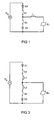
- FIG. 1 shows the block diagram of a first variant of the half-bridge inductor according to the invention.
- This has two serial switch branches, each of which comprises a current valve D1, D2, for example a diode, and a switch S1, S2, for example a transistor, in particular a field-effect transistor (FET) or MOSFET.
- the middle point of the series connection of the two switch branches is connected to a lamp branch which comprises a choke L and a dielectric barrier discharge lamp EL connected in series therewith.
- the lamp branch is connected in parallel with one of the two switch branches.
- the terminals of the series circuit of the two switch branches are connected to an electrical supply source U 0 .
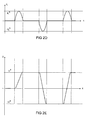
- Fig. 2a shows the drive signals of the two switches S1 and S2.
- Fig. 2b only during the "on-time”, that is, when exactly one of the two switches S1, S2 is closed, a pulse-shaped current I L flowing through the inductor L.
- the "pause times” ie when none of the two switches S1, S2 is closed, no current flows through the inductor L. Accordingly, the voltage U at the lamp terminals increases when the circuit is switched on for the first time, ie when the dielectric barrier discharge lamp EL is still open is not ignited and acts as an electrical capacitor, on.
- the amplitude of the current pulses I L increases with each pulse, that of the voltage with each period.
- This resonant behavior continues until the ignition of the dielectric barrier discharge lamp EL.
- FIG. 3 shows a sub-variant of the half-bridge inductor described in FIG. Their function differs from the function previously described in connection with FIGS. 2a-2e only in that two different inductances L1, L2 are now determining for the alternating current pulses and consequently for the rising and falling edges of the lamp voltage U.
- the inductor L is split in Fig. 2 in the two inductors L1 and L2 and also integrated into the two switch branches of the half-bridge inductor, ie in each case to the serial switch and diode.
- the second choke ultimately yields a further degree of freedom for influencing the voltage edges.
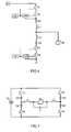
- FIG. 4 shows a concrete exemplary embodiment of the basic circuit of the second variant of the half-bridge inductor according to the invention shown in FIG. 3 with two inductors L1 and L2.
- This circuit is for the operation of a flat dielectric barrier discharge lamp of the type PLANON® (OSRAM GmbH, see, for example, web link on the Internet: http://www.osram.de/ueber_uns/umwelt/ effort/planon.html#) with With a system power of approximately 213 W, luminance densities of 6310 Cd / m 2 and more can be achieved with a luminous efficacy of, for example, 8.3 Cd / W and more Luminous efficiency is approximately 30% higher than with a conventional class E converter circuit
- Each of the two switch circuits comprises as switches four MOSFET (Metal Oxide Semiconductor Field Effect Transistor) T1 to T4 or T5 to T8 type 17N80 COOLMOS (Infineon ), so as not to burden the individual transistors with the high input voltage
- the two diodes D1, D2 are also designed in SiC technology for a voltage of 1200 V and a current of 5 A.
- the two inductors L1, L2 have the same inductance of 104 ⁇ H each here.
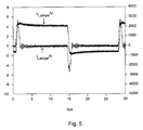
- FIG. 5 shows the associated timing diagram for the lamp current i EL in amperes (A) and the lamp voltage u EL in volts (V); the unit of the Y-axis is microseconds ( ⁇ s). Accordingly, the current pulses have a duration of approximately 1 ⁇ s and a repetition frequency of 36.36 kHz.
- the duty cycle is 50%.
- the efficiency of the circuit is more than 85%. In an overload operation the circuit of Fig. 4 with 752 W, a luminance of more than 20 000 Cd / m 2 is achieved.
- the current pulses had a duration of 0.6 ⁇ s with a pulse repetition frequency of 67.8 kHz.
- FIG. 6 shows the corresponding timing diagram for unequal inductance values for the two inductors L1 and L2, namely 104 ⁇ H and 14 ⁇ H, respectively.
- FIG. 7 shows a first basic circuit of a full-bridge throttle converter according to the invention with a symmetrical topology.
- the resulting symmetrical lamp voltage is symmetrical in construction of the dielectric barrier discharge lamp, i.
- EMC Electromagnetic Compatibility
- the dielectric barrier discharge lamp EL is connected via two inductors L, L 'between the centers of each two series circuits with two switch branches in the manner of a full bridge.
- Each of the four switch branches consists of a series connection of a transistor T1 to T4 and a diode D1 to D4.
- a capacitor C is also connected.
- FIGS. 8a-8c show the circuit diagram of the circuit from FIG. 7.
- the positive or negative current pulses I L are generated whose amplitudes I L + and I L- are the same in this case.
- a rectangular voltage signal U symmetrical with respect to the zero line results at the terminals of the dielectric barrier discharge lamp EL.
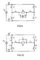
- FIG. 9 shows a sub-variant of the full-bridge throttle converter shown in FIG.
- the drawn in Fig. 7 diodes D1 to D4 are pulled out of the switch branches and connected as ever a common diode D5 and D6 in the common leads for the full bridge switch branches.
- the capacitor C is replaced by a series circuit of two capacitors C1 and C2, the center point for the symmetrization of the lamp voltage with constant potential, such as ground, is connected.
- the resulting symmetrical lamp voltage is advantageous in the case of a symmetrical design of the dielectric barrier discharge lamp from the EMC point of view.
- FIG. 10 shows a further sub-variant of the full-bridge throttle converter according to the invention. It differs from the variant shown in Fig. 9 only in that in each switch branch additionally each a choke L1 - L4 is connected. This makes it possible to choose the height of the positive and negative current pulses, and consequently the edges of the square-wave voltage for the lamp differently, by choosing the inductances of the inductors L1 and L4 not equal to those of the inductors L2 and L3.
Landscapes
- Circuit Arrangements For Discharge Lamps (AREA)
- Inverter Devices (AREA)
- Dc-Dc Converters (AREA)
Applications Claiming Priority (1)
| Application Number | Priority Date | Filing Date | Title |
|---|---|---|---|
| DE102005034505A DE102005034505A1 (de) | 2005-07-20 | 2005-07-20 | Schaltungsanorndung mit transformatorlosem Wandler mit Drossel für den gepulsten Betrieb von dielektrischen Barriere-Entladungslampen |
Publications (2)
| Publication Number | Publication Date |
|---|---|
| EP1753272A2 true EP1753272A2 (fr) | 2007-02-14 |
| EP1753272A3 EP1753272A3 (fr) | 2010-01-13 |
Family
ID=37198461
Family Applications (1)
| Application Number | Title | Priority Date | Filing Date |
|---|---|---|---|
| EP06014622A Withdrawn EP1753272A3 (fr) | 2005-07-20 | 2006-07-13 | Circuit convertisseur comprenant une inductance au lieu d' un transformateur, pour l' alimentation pulsée d' une lampe à barrière diélectrique. |
Country Status (7)
| Country | Link |
|---|---|
| US (1) | US7355351B2 (fr) |
| EP (1) | EP1753272A3 (fr) |
| JP (1) | JP2007027133A (fr) |
| KR (1) | KR100840027B1 (fr) |
| CN (1) | CN1968562A (fr) |
| DE (1) | DE102005034505A1 (fr) |
| TW (1) | TWI361638B (fr) |
Cited By (2)
| Publication number | Priority date | Publication date | Assignee | Title |
|---|---|---|---|---|
| DE102007054330A1 (de) | 2007-11-14 | 2009-05-20 | Osram Gesellschaft mit beschränkter Haftung | Vorschaltgerät mit DBD-Lampe |
| FR2939006A1 (fr) * | 2008-11-26 | 2010-05-28 | Saint Gobain | Ballast pulse pour lampes planes |
Families Citing this family (7)
| Publication number | Priority date | Publication date | Assignee | Title |
|---|---|---|---|---|
| US7402962B1 (en) * | 2007-01-26 | 2008-07-22 | Pacifictech Microelectronics, Inc. | System and methods of driving an electroluminescent lamp |
| KR101433658B1 (ko) * | 2007-03-13 | 2014-08-26 | 삼성전자주식회사 | 광원 구동 장치, 광원 구동 방법 및 이들을 이용한 표시장치 |
| JP5605249B2 (ja) * | 2011-02-03 | 2014-10-15 | 株式会社村田製作所 | 放電ランプ点灯装置 |
| CN102306642A (zh) * | 2011-09-22 | 2012-01-04 | 华东师范大学 | 一种电感值可调的片上集成电感 |
| CN102695345B (zh) * | 2012-06-01 | 2014-03-26 | 雷锡社 | 能效型智能镇流器 |
| GB2522699A (en) * | 2014-02-04 | 2015-08-05 | Clean Power Patents Ltd | Lighting Unit and Driver circuit |
| CN114666935B (zh) * | 2022-03-03 | 2025-01-17 | 平顶山学院 | 一种介质阻挡放电灯的双极性脉冲电流型驱动电路及设备 |
Citations (4)
| Publication number | Priority date | Publication date | Assignee | Title |
|---|---|---|---|---|
| US5604410A (en) | 1993-04-05 | 1997-02-18 | Patent-Treuhand-Gesellschaft Fur Elektrische Gluhlampen Mbh | Method to operate an incoherently emitting radiation source having at least one dielectrically impeded electrode |
| US5994849A (en) | 1995-07-18 | 1999-11-30 | Patent-Treuhand-Gesellschaft Fuer Electrische Gluehlampen Mbh | Method for operating a lighting system and suitable lighting system therefor |
| US6097155A (en) | 1997-04-30 | 2000-08-01 | Patent-Treuhand-Gesellschaft Fuer Elektrische Gluehlampen Mbh | Fluorescent lamp |
| EP0927506B1 (fr) | 1997-07-22 | 2001-10-31 | Patent-Treuhand-Gesellschaft für elektrische Glühlampen mbH | Systeme d'eclairage comprenant une lampe a decharge a barriere dielectrique et un circuit pour produire des sequences d'impulsions |
Family Cites Families (24)
| Publication number | Priority date | Publication date | Assignee | Title |
|---|---|---|---|---|
| US3996495A (en) | 1975-07-25 | 1976-12-07 | North American Philips Corporation | High efficiency ballast system for electric discharge lamps |
| AU555174B2 (en) * | 1981-09-18 | 1986-09-18 | Oy Helvar | Electronic ballast for a discharge lamp |
| US4405889A (en) | 1981-10-29 | 1983-09-20 | Gte Products Corporation | Power supply for repetitive discharge apparatus |
| US4996462A (en) * | 1988-07-27 | 1991-02-26 | Siemens Aktiengesellschaft | Electronic ballast for fluoroscent lamps |
| JPH0521179A (ja) * | 1991-07-15 | 1993-01-29 | Matsushita Electric Works Ltd | 放電灯点灯装置 |
| CA2104737C (fr) * | 1992-08-26 | 1997-01-28 | Minoru Maehara | Onduleur |
| US5959410A (en) * | 1997-01-29 | 1999-09-28 | Matsushita Electric Works R&D Laboratory, Inc. | Charge pump power factor correction circuit for power supply for gas discharge lamp |
| JP3829507B2 (ja) * | 1997-12-12 | 2006-10-04 | 松下電工株式会社 | 電子バラストおよびhidランプ制御回路 |
| JP2000003798A (ja) * | 1998-04-16 | 2000-01-07 | Toshiba Lighting & Technology Corp | 放電ランプ点灯装置および照明装置 |
| JP3271059B2 (ja) * | 1998-05-25 | 2002-04-02 | 株式会社日立製作所 | 電気車用3相インバータ装置 |
| CN1239052C (zh) * | 1999-05-14 | 2006-01-25 | 皇家菲利浦电子有限公司 | 电路设置 |
| DE19963289A1 (de) * | 1999-12-27 | 2001-06-28 | Tridonic Bauelemente | Schaltungsanordnung zum Betreiben einer Gasentladungslampe |
| US6437515B1 (en) * | 2000-01-18 | 2002-08-20 | Matsushita Electric Works, Ltd. | Discharge lamp lighting device of high startability with high pulse voltage |
| DE10005975A1 (de) * | 2000-02-09 | 2001-08-16 | Patent Treuhand Ges Fuer Elektrische Gluehlampen Mbh | Betriebsverfahren für eine Entladungslampe mit mindestens einer dielektrisch behinderten Elektrode |
| JP3947895B2 (ja) * | 2000-02-24 | 2007-07-25 | 株式会社日立製作所 | 照明装置用点灯装置 |
| US6380694B1 (en) * | 2000-09-22 | 2002-04-30 | Matsushita Electric Works R & D Laboratory | Variable structure circuit topology for HID lamp electronic ballasts |
| JP4190734B2 (ja) * | 2001-01-15 | 2008-12-03 | ウシオ電機株式会社 | 誘電体バリア放電ランプ光源装置 |
| JP2003142287A (ja) * | 2001-10-31 | 2003-05-16 | Hitachi Ltd | 平面放電ランプ用点灯回路 |
| DE10200004A1 (de) * | 2002-01-02 | 2003-07-17 | Philips Intellectual Property | Elektronische Schaltung und Verfahren zum Betreiben einer Hochdrucklampe |
| AU2002358230A1 (en) * | 2002-01-08 | 2003-07-24 | Koninklijke Philips Electronics N.V. | Circuit for a gas-discharge lamp |
| FR2858110B1 (fr) * | 2003-07-23 | 2006-01-27 | Saint Gobain | Dispositif d'alimentation electrique destine a alimenter au moins deux electrodes |
| DE10336858A1 (de) * | 2003-08-11 | 2005-03-24 | Patent-Treuhand-Gesellschaft für elektrische Glühlampen mbH | Elektronisches Vorschaltgerät für eine mit iterativen Spannungspulsen zu betreibende Lampe |
| DE10349548A1 (de) * | 2003-10-22 | 2005-05-25 | Patent-Treuhand-Gesellschaft für elektrische Glühlampen mbH | Betriebsschaltung für dielektrisch behinderte Entladungslampe mit Überspannungsschutzschaltung |
| JP2006244872A (ja) | 2005-03-03 | 2006-09-14 | Lecip Corp | 誘電体バリア放電灯制御装置 |
-
2005
- 2005-07-20 DE DE102005034505A patent/DE102005034505A1/de not_active Withdrawn
-
2006
- 2006-07-12 US US11/485,231 patent/US7355351B2/en not_active Expired - Fee Related
- 2006-07-13 EP EP06014622A patent/EP1753272A3/fr not_active Withdrawn
- 2006-07-18 TW TW095126139A patent/TWI361638B/zh not_active IP Right Cessation
- 2006-07-19 KR KR1020060067353A patent/KR100840027B1/ko not_active Expired - Fee Related
- 2006-07-20 JP JP2006198684A patent/JP2007027133A/ja active Pending
- 2006-07-20 CN CNA200610163915XA patent/CN1968562A/zh active Pending
Patent Citations (4)
| Publication number | Priority date | Publication date | Assignee | Title |
|---|---|---|---|---|
| US5604410A (en) | 1993-04-05 | 1997-02-18 | Patent-Treuhand-Gesellschaft Fur Elektrische Gluhlampen Mbh | Method to operate an incoherently emitting radiation source having at least one dielectrically impeded electrode |
| US5994849A (en) | 1995-07-18 | 1999-11-30 | Patent-Treuhand-Gesellschaft Fuer Electrische Gluehlampen Mbh | Method for operating a lighting system and suitable lighting system therefor |
| US6097155A (en) | 1997-04-30 | 2000-08-01 | Patent-Treuhand-Gesellschaft Fuer Elektrische Gluehlampen Mbh | Fluorescent lamp |
| EP0927506B1 (fr) | 1997-07-22 | 2001-10-31 | Patent-Treuhand-Gesellschaft für elektrische Glühlampen mbH | Systeme d'eclairage comprenant une lampe a decharge a barriere dielectrique et un circuit pour produire des sequences d'impulsions |
Cited By (4)
| Publication number | Priority date | Publication date | Assignee | Title |
|---|---|---|---|---|
| DE102007054330A1 (de) | 2007-11-14 | 2009-05-20 | Osram Gesellschaft mit beschränkter Haftung | Vorschaltgerät mit DBD-Lampe |
| WO2009062835A1 (fr) * | 2007-11-14 | 2009-05-22 | Osram Gesellschaft mit beschränkter Haftung | Ballast avec lampe dbd |
| FR2939006A1 (fr) * | 2008-11-26 | 2010-05-28 | Saint Gobain | Ballast pulse pour lampes planes |
| WO2010061131A3 (fr) * | 2008-11-26 | 2010-11-25 | Saint-Gobain Glass France | Ballast pulse pour lampes planes |
Also Published As
| Publication number | Publication date |
|---|---|
| DE102005034505A1 (de) | 2007-02-01 |
| US20070018590A1 (en) | 2007-01-25 |
| US7355351B2 (en) | 2008-04-08 |
| EP1753272A3 (fr) | 2010-01-13 |
| TWI361638B (en) | 2012-04-01 |
| KR100840027B1 (ko) | 2008-06-19 |
| CN1968562A (zh) | 2007-05-23 |
| JP2007027133A (ja) | 2007-02-01 |
| KR20070011157A (ko) | 2007-01-24 |
| TW200721913A (en) | 2007-06-01 |
Similar Documents
| Publication | Publication Date | Title |
|---|---|---|
| EP0927506B1 (fr) | Systeme d'eclairage comprenant une lampe a decharge a barriere dielectrique et un circuit pour produire des sequences d'impulsions | |
| DE19750168B4 (de) | Drei Spannungsversorgungen für Treiberschaltungen von Leistungs-Halbleiterschaltern | |
| DE68911005T2 (de) | Vollbrückenschaltanordnung. | |
| EP1520331B1 (fr) | Procede et ensemble circuit pour limiter une surtension | |
| EP0781077A2 (fr) | Circuit pour alimenter une lampe | |
| EP0781078A2 (fr) | Circuit pour alimenter des lampes à barrière diélectrique par impulsions | |
| EP2089961A1 (fr) | Convertisseur cc/cc autohétérodyne et procédé à cet effet | |
| DE202007005779U1 (de) | MF-Plasmaleistungsgenerator | |
| EP3512085A1 (fr) | Convertisseur cc/cc avec circuits résonnants et pentes commutations ultra-abrupts | |
| DE102020201810B4 (de) | Stromrichter-Schaltung | |
| EP1500196B1 (fr) | Circuit en demi-pont | |
| DE3813672C2 (de) | Wechselrichter für eine induktive Last | |
| EP1753272A2 (fr) | Circuit convertisseur comprenant une inductance au lieu d' un transformateur, pour l' alimentation pulsée d' une lampe à barrière diélectrique. | |
| EP3667917A1 (fr) | Circuit de commande pour un circuit oscillateur destiné au fonctionnement des oscillateurs à alimentation parallèle | |
| EP1710898B1 (fr) | Convertisseur de tension commutable | |
| EP2168229A1 (fr) | Ensemble circuit pourvu d'un transformateur de tension et procédé correspondant | |
| EP3317967B1 (fr) | Circuit de commutation destiné à la commande d'un transistor | |
| EP1071210B1 (fr) | Montage de circuit | |
| EP1507445B1 (fr) | Ballast electronique pour faire fonctionner une lamp avec des impulsions de tension itérative | |
| EP0893884A2 (fr) | Procédé et dispositif servant à commander un thyristor blocable | |
| EP1282342B1 (fr) | Cicuit auto-oscillant | |
| EP0824848B1 (fr) | Systeme de regulation de puissance d'une lampe a decharge a haute pression a courant alternatif, notamment pour des vehicules a moteur | |
| EP0992113B1 (fr) | Commande a demi-pont sans pics de courant de polarisation au collecteur | |
| EP1738618B1 (fr) | Circuit d'attaque pour convertisseur | |
| EP3120447A1 (fr) | Circuit électrique comprenant un demi-pont |
Legal Events
| Date | Code | Title | Description |
|---|---|---|---|
| PUAI | Public reference made under article 153(3) epc to a published international application that has entered the european phase |
Free format text: ORIGINAL CODE: 0009012 |
|
| AK | Designated contracting states |
Kind code of ref document: A2 Designated state(s): AT BE BG CH CY CZ DE DK EE ES FI FR GB GR HU IE IS IT LI LT LU LV MC NL PL PT RO SE SI SK TR |
|
| AX | Request for extension of the european patent |
Extension state: AL BA HR MK YU |
|
| PUAL | Search report despatched |
Free format text: ORIGINAL CODE: 0009013 |
|
| AK | Designated contracting states |
Kind code of ref document: A3 Designated state(s): AT BE BG CH CY CZ DE DK EE ES FI FR GB GR HU IE IS IT LI LT LU LV MC NL PL PT RO SE SI SK TR |
|
| AX | Request for extension of the european patent |
Extension state: AL BA HR MK RS |
|
| 17P | Request for examination filed |
Effective date: 20100208 |
|
| 17Q | First examination report despatched |
Effective date: 20100308 |
|
| RAP1 | Party data changed (applicant data changed or rights of an application transferred) |
Owner name: OSRAM GESELLSCHAFT MIT BESCHRAENKTER HAFTUNG |
|
| AKX | Designation fees paid |
Designated state(s): AT BE BG CH CY CZ DE DK EE ES FI FR GB GR HU IE IS IT LI LT LU LV MC NL PL PT RO SE SI SK TR |
|
| RAP1 | Party data changed (applicant data changed or rights of an application transferred) |
Owner name: OSRAM AG |
|
| RAP1 | Party data changed (applicant data changed or rights of an application transferred) |
Owner name: OSRAM GMBH |
|
| RAP1 | Party data changed (applicant data changed or rights of an application transferred) |
Owner name: OSRAM GMBH |
|
| STAA | Information on the status of an ep patent application or granted ep patent |
Free format text: STATUS: THE APPLICATION IS DEEMED TO BE WITHDRAWN |
|
| 18D | Application deemed to be withdrawn |
Effective date: 20150203 |