EP1753285B1 - Wand- bzw. deckenkonstruktion aus schläuchen - Google Patents
Wand- bzw. deckenkonstruktion aus schläuchen Download PDFInfo
- Publication number
- EP1753285B1 EP1753285B1 EP05741837A EP05741837A EP1753285B1 EP 1753285 B1 EP1753285 B1 EP 1753285B1 EP 05741837 A EP05741837 A EP 05741837A EP 05741837 A EP05741837 A EP 05741837A EP 1753285 B1 EP1753285 B1 EP 1753285B1
- Authority
- EP
- European Patent Office
- Prior art keywords
- wall
- roof construction
- tubes
- tube
- section
- Prior art date
- Legal status (The legal status is an assumption and is not a legal conclusion. Google has not performed a legal analysis and makes no representation as to the accuracy of the status listed.)
- Expired - Lifetime
Links
- 238000010276 construction Methods 0.000 title claims abstract description 19
- 230000003068 static effect Effects 0.000 claims description 4
- 238000003825 pressing Methods 0.000 claims description 2
- 239000000463 material Substances 0.000 description 4
- XLYOFNOQVPJJNP-UHFFFAOYSA-N water Substances O XLYOFNOQVPJJNP-UHFFFAOYSA-N 0.000 description 4
- 238000005452 bending Methods 0.000 description 3
- 230000006978 adaptation Effects 0.000 description 2
- 239000011248 coating agent Substances 0.000 description 2
- 238000000576 coating method Methods 0.000 description 2
- 238000001816 cooling Methods 0.000 description 2
- 230000000694 effects Effects 0.000 description 2
- 229920000840 ethylene tetrafluoroethylene copolymer Polymers 0.000 description 2
- 238000010438 heat treatment Methods 0.000 description 2
- 238000004519 manufacturing process Methods 0.000 description 2
- 230000007704 transition Effects 0.000 description 2
- 238000009435 building construction Methods 0.000 description 1
- 238000005253 cladding Methods 0.000 description 1
- 238000011109 contamination Methods 0.000 description 1
- 239000013013 elastic material Substances 0.000 description 1
- QHSJIZLJUFMIFP-UHFFFAOYSA-N ethene;1,1,2,2-tetrafluoroethene Chemical group C=C.FC(F)=C(F)F QHSJIZLJUFMIFP-UHFFFAOYSA-N 0.000 description 1
- 230000002349 favourable effect Effects 0.000 description 1
- 238000005429 filling process Methods 0.000 description 1
- 238000010413 gardening Methods 0.000 description 1
- JEIPFZHSYJVQDO-UHFFFAOYSA-N iron(III) oxide Inorganic materials O=[Fe]O[Fe]=O JEIPFZHSYJVQDO-UHFFFAOYSA-N 0.000 description 1
- 230000002262 irrigation Effects 0.000 description 1
- 238000003973 irrigation Methods 0.000 description 1
- 238000012423 maintenance Methods 0.000 description 1
- 238000007726 management method Methods 0.000 description 1
- 230000001404 mediated effect Effects 0.000 description 1
- 230000002040 relaxant effect Effects 0.000 description 1
- 238000003860 storage Methods 0.000 description 1
- 230000037072 sun protection Effects 0.000 description 1
- 230000009182 swimming Effects 0.000 description 1
Images



Classifications
-
- A—HUMAN NECESSITIES
- A01—AGRICULTURE; FORESTRY; ANIMAL HUSBANDRY; HUNTING; TRAPPING; FISHING
- A01G—HORTICULTURE; CULTIVATION OF VEGETABLES, FLOWERS, RICE, FRUIT, VINES, HOPS OR SEAWEED; FORESTRY; WATERING
- A01G9/00—Cultivation in receptacles, forcing-frames or greenhouses; Edging for beds, lawn or the like
- A01G9/24—Devices or systems for heating, ventilating, regulating temperature, illuminating, or watering, in greenhouses, forcing-frames, or the like
- A01G9/241—Arrangement of opening or closing systems for windows and ventilation panels
- A01G9/242—Arrangement of opening or closing systems for windows and ventilation panels for greenhouses with flexible coverings
-
- A—HUMAN NECESSITIES
- A01—AGRICULTURE; FORESTRY; ANIMAL HUSBANDRY; HUNTING; TRAPPING; FISHING
- A01G—HORTICULTURE; CULTIVATION OF VEGETABLES, FLOWERS, RICE, FRUIT, VINES, HOPS OR SEAWEED; FORESTRY; WATERING
- A01G9/00—Cultivation in receptacles, forcing-frames or greenhouses; Edging for beds, lawn or the like
- A01G9/22—Shades or blinds for greenhouses, or the like
- A01G9/225—Inflatable structures
-
- Y—GENERAL TAGGING OF NEW TECHNOLOGICAL DEVELOPMENTS; GENERAL TAGGING OF CROSS-SECTIONAL TECHNOLOGIES SPANNING OVER SEVERAL SECTIONS OF THE IPC; TECHNICAL SUBJECTS COVERED BY FORMER USPC CROSS-REFERENCE ART COLLECTIONS [XRACs] AND DIGESTS
- Y02—TECHNOLOGIES OR APPLICATIONS FOR MITIGATION OR ADAPTATION AGAINST CLIMATE CHANGE
- Y02A—TECHNOLOGIES FOR ADAPTATION TO CLIMATE CHANGE
- Y02A40/00—Adaptation technologies in agriculture, forestry, livestock or agroalimentary production
- Y02A40/10—Adaptation technologies in agriculture, forestry, livestock or agroalimentary production in agriculture
- Y02A40/25—Greenhouse technology, e.g. cooling systems therefor
Definitions
- the invention relates to a wall or ceiling construction of juxtaposed hoses having fixedly mounted at one point of their circumference mounted supports, the hoses in the inflated state have round cross-section and form a closed boundary surface and have a flat cross section in the deflated state, so that gaps between the tubes, in particular for the passage of light arise.
- US 4,301,626 and US 4,290,242 are false ceilings for greenhouses known, which consist of juxtaposed hoses that protect the plants from sunlight in the inflated state.
- the hoses are made of limp material, so that they hang like a flag during evacuation and form a translucent rust.
- the invention is based on the consideration that such constructions would have a much wider range of application if they were designed so that they can be used as outer shell of buildings. Depending on the purpose of use, opening and closing the construction would then allow or prevent the sun, rain and snow from entering the interior.
- each hose has a further holder on a location of its circumference which is fixedly mounted on the holders, to which a force directed away from the stationary holder can be applied.
- the cross-section and especially the orientation of the hoses during the emptying and filling process is controlled by the preferably applied by means of a rope radial force.
- the hoses have a defined configuration and position not only in the closed, but also in the open state.
- a particularly interesting field of application is the use of the invention for winter sports resorts in the high mountains.
- the roof is opened (air is sucked out of the hoses).
- the snow can fall on the otherwise covered ski slope.
- Accumulating snow load on the roof / wall skin or on the primary static carrying system is avoided.
- This allows a greatly reduced Carrying structure with increased architectural aesthetics in sensitive landscape environment and a serious reduction of planning, manufacturing, material, transport and assembly costs.
- the transport effort and assembly work in rough alpine terrain are significantly simplified.
- the assembly takes place with high dimensional tolerance and adaptability. Maintenance work can be carried out with little technical means and simple training.
- the naturally fallen amount of snow is available unrestricted inside.
- no artificial snow must be produced in principle.
- the construction costs and the burden on the environment are greatly reduced.
- the roof In cold, fair weather in winter, the roof can be opened. The wintery outside atmosphere penetrates into the interior of the ski slope roofing. During summer, the roof remains closed, thus providing both weather protection and temperature envelope.
- the air cushion principle of the hoses has a heat-insulating effect and stabilizes the desired room temperature. Reflective coating on the inside of the room and white coating on the outside further enhance the temperature-insulating effect of the roof cladding. A further increase in temperature control is achieved by cooling the air injected into the hoses.
- the lightweight design of the construction favors their adaptation to existing facilities and the economically and architecturally favorable management of any construction tasks of this kind.
- a plurality of hoses 1 are arranged side by side so that they form a closed roof surface for a hall in the dotted state illustrated dotted.
- the entire air supply can be switched to recirculation mode.
- the pneumatic construction can be actively used to control the temperature of the covered space via an integrated cooling and heating system. In order to avoid contamination, especially with transparent hoses, the circulating air can be cleaned in a filter system.
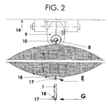
- Fig. 2 The connection between the hoses 1 and the carrier profiles 14 of the primary support system 23 is in particular made Fig. 2 in which in turn the hoses are shown in the filled (dotted) and in the deflated state.
- a pendulum suspended connection element 9 which forms a clamp for the hose back.
- a piping in the form of the crowned flange This forms the stationary support of the hose 1 to the support system 23.
- This bracket is mediated by profiles 10, which surround the flanges on the hose back. These profiles 10 are made of highly elastic material and continuously adjustable in the connecting elements.
- Fig. 2 clearly visible possibility to set by a cable 17 the position and configuration of the tube 1 with inflated and empty tube 1 precisely.
- inflated tube 1 dotted
- the rope is in a relaxed state (E) in the form of a sleeve movable holder 18. If the rope in the tensioned state (G) transferred, so the hose 1 assumes strip shape and points to the adjacent hoses a long distance.
- ETFE films ethylene tetrafluoroethylene
- PVC PES films are preferably used as a material for the hoses.
- any material is suitable, which can join the typical for the invention change between the emptied and the inflated shape of the hose several times.
- Fig. 3 shows an in Fig. 1 indicated arrangement of the clamping unit 20 in the ceiling region of the hall and in sections transverse to the extension of the tubes, parallel to the direction of the tubes and in plan view of the empty tube 1.
- Das Cable 17 is supplied from both sides via cable sheaths 19 to the tensioning unit. The two ends of the cable 17 are wound in opposite directions to prevent rotation of the empty tube.
- the hoses 1 in the filled state form a facade or wall.
- the transition from the circular to the flat cross section of the hoses 1 is associated with a transition of the cables 17 from the relaxed (E) to the tensioned (G) state.
- the ropes 17 are guided as in the first embodiment in sleeves on the inside of the hoses 1, which form the movable support of the cables 17. Now moves the clamping unit 20 in Fig. 6 to the left shortened the rope 17 and pulls the empty tube 1 in the right position. Thus, the initially closed wall is resolved into a series of slats.
Landscapes
- Life Sciences & Earth Sciences (AREA)
- Environmental Sciences (AREA)
- Building Environments (AREA)
- Tents Or Canopies (AREA)
- Sink And Installation For Waste Water (AREA)
- On-Site Construction Work That Accompanies The Preparation And Application Of Concrete (AREA)
- Joining Of Building Structures In Genera (AREA)
- Supports For Pipes And Cables (AREA)
Description
- Die Erfindung bezieht sich auf eine Wand- bzw. Deckenkonstruktion aus nebeneinander angeordneten Schläuchen, die an einer Stelle ihres Umfangs ortsfest gelagerte Halterungen aufweisen, wobei die Schläuche in aufgeblasenem Zustand runden Querschnitt aufweisen und eine geschlossene Begrenzungsfläche bilden und in entleertem Zustand einen flachen Querschnitt aufweisen, sodass zwischen den Schläuchen Zwischenräume insbesondere für den Lichtdurchtritt entstehen.
- Aus
US 4,301,626 undUS 4,290, 242 sind Zwischendecken für Gewächshäuser bekannt, welche aus nebeneinander angeordneten Schläuchen bestehen, die im aufgeblasenen Zustand die Pflanzen vor Sonnenbestrahlung schützen. Die Schläuche bestehen aus biegeschlaffem Material, sodass sie bei Evakuierung fahnenartig herabhängen und einen lichtdurchlässigen Rost bilden. - Aus
US 6,000,170 undUS 6,442,903 sind Wand- bzw. Deckenkonstruktionen gemäß dem Oberbegriff des Anspruch 1 bekannt. Diese Dokumente beschäftigen sich aber nicht mit der Problematik, eine witterungsdichte Wand- bzw. Deckenkonstruktion zu bilden. - Der Erfindung liegt die Überlegung zugrunde, dass derartige Konstruktionen einen wesentlich vergrößerten Anwendungsbereich hätten, wenn sie so ausgebildet würden, dass sie als Außenhülle von Gebäuden verwendbar sind. Je nach Verwendungszweck würde dann durch das Öffnen und Schließen der Konstruktion der Einfall von Sonne, Regen und Schnee ins Innere ermöglicht oder verhindert werden.
- Zur Lösung der gestellten Aufgabe ist vorgesehen, dass jeder Schlauch an einer den ortsfest gelagerten Halterungen gegenüberliegenden Stelle seines Umfangs eine weitere Halterung aufweist, auf welche eine von der ortsfesten Halterung weg gerichtete Kraft aufbringbar ist. Durch diese Maßnahme wird der Querschnitt und vor allem die Orientierung der Schläuche während des Entleerungs- und Füllvorgangs durch die vorzugsweise mittels eines Seils aufgebrachte radiale Kraft kontrolliert. Die Schläuche weisen nicht nur im geschlossenen, sondern auch im geöffneten Zustand eine definierte Konfiguration und Lage auf.
- Durch die Trennbarkeit der Schläuche entsteht aber das Problem, sie bei geschlossener Dachhaut hinreichend fest aneinanderzudrücken, um Witterungseinflüsse abzuhalten. Diese Aufgabe wird erfindungsgemäß durch in das primäre statische Tragsystem integrierte biege- und verwindungssteife Begrenzungsprofile gelöst, welche die am Rande liegenden Schläuche am Ausweichen hindern.
- Ein besonders interessantes Anwendungsgebiet ist die Nutzung der Erfindung für Wintersportstätten im Hochgebirge. Bei Schneefall wird das Dach geöffnet (Luft wird aus den Schläuchen abgesaugt). Der Schnee kann auf die ansonsten überdachte Schipiste fallen. Anfallende Schneelast auf der Dach/Wandhaut bzw. auf dem primären statischen Tragesystem wird vermieden. Dies ermöglicht eine stark reduzierte Tragekonstruktion mit erhöhter architektonischer Ästhetik in sensibler landschaftlicher Umgebung und eine gravierende Reduzierung der Planungs-, Fertigungs-, Material-, Transport- und Montagekosten. Der Transportaufwand und die Montagearbeit in unwegsamem alpinem Gelände werden entscheidend vereinfacht. Die Montage erfolgt mit hoher Maßtoleranz und Anpassungsfähigkeit. Wartungsarbeiten sind mit geringen technischen Mitteln und einfacher Schulung durchführbar. Die natürlich gefallene Schneemenge steht im Inneren uneingeschränkt zur Verfügung. Dadurch muss im Winter im Prinzip kein Kunstschnee produziert werden. Damit werden der Energieaufwand und der Wasserbedarf für Kunstschnee-Erzeugung stark reduziert. Dies ergibt ein geringeres Volumen an künstlicher Wasserspeicherung. Die Baukosten und die Belastung der Umwelt werden stark vermindert.
- Bei kaltem Schönwetter im Winter kann das Dach geöffnet werden. Die winterliche Außenatmosphäre dringt in das Innere der Schipistenüberdachung. Während der Sommerzeit bleibt das Dach geschlossen und bietet so zugleich Wetterschutz und Temperaturhülle.
- Das Luftkissenprinzip der Schläuche wirkt wärmedämmend und stabilisiert die gewünschte Raumtemperatur. Durch reflektierende Beschichtung zur Rauminnenseite und weißer Beschichtung zur Außenseite wird die temperaturisolierende Wirkung der Dachhaut zusätzlich verstärkt, Eine weitere Steigerung der Temperaturregelung wird durch Kühlung der in die Schläuche eingeblasenen Luft erreicht.
- Ein weiteres interessanten Anwendungsgebiet liegt im Bereich von leicht öffen- und schließbaren Überdachungen für Fußballstadien - insbesondere über dem Spiel- bzw. Rasenbereich. Bei Spiel / Regen / Schnee wird das Dach geschlossen. Die während der Spielzeit fallende Schneemenge kann durch Erwärmung der eingeblasenen Luft permanent abgetaut werden. Ansonsten bleibt das Dach geöffnet, wodurch die notwendige Rasenbewässerung und auch das natürliche Raumklima bei Schönwetter gesichert ist.
- Die Leichtbauweise der Konstruktion begünstigt ihre Adaptierung auch auf bereits vorhandenen Anlagen bzw. die wirtschaftlich und architektonisch günstige Bewältigung allfälliger Bauaufgaben dieser Art.
- Eine Adaptierung der Anlage für andere Sportarten (Schwimmen, Tennis), bei denen Wind und Regen abgehalten werden sollen, ist naheliegend. Auch die Verwendung der Erfindung für Gartenkulturen bietet sich an, um Regen und Sonne in kontrollierter Weise zuführen zu können. Im allgemeinen Hochbau ergibt sich durch die geschützte Maßnahme ein stufenlos einstellbarer Sonnenschutz.
- Konstruktive Einzelheiten der Erfindung werden anschließend anhand der Zeichnung erläutert. In dieser ist
- Fig. 1
- ein Querschnitt durch eine erfindungsgemäß gebaute Sporthalle,
- Fig. 2
- ein Detail aus
Fig. 1 , - Fig. 3
- ein weiteres Detail aus
Fig. 1 - Fig. 4
- zeigt ein zweites Ausführungsbeispiel in Seitenansicht und Horizontalschnitt,
- Fig. 5
- im Vertikalschnitt;
- Fig. 6
- ist ein vergrößerter Ausschnitt aus
Fig. 5 . - Beim Ausführungsbeispiel nach
Fig. 1 bis 3 ist an einem primären Tragsystem 23 eine Vielzahl von Schläuchen 1 nebeneinander angeordnet, sodass diese im gepunktet dargestellten aufgeblasenen Zustand ein geschlossene Dachfläche für eine Halle bilden. Das Aufblasen und Entleeren der Schläuche 1 erfolgt über Rohre 7, in welchen Überdruck bzw. Unterdruck herrscht und in welche die Schläuche 1 einzeln angeschlossen werden können. Die gesamte Luftversorgung kann auf Umluftbetrieb umgeschaltet werden. Damit kann über ein integriertes Kühl- und Heizsystem bei Bedarf die pneumatische Konstruktion aktiv für die Temperatursteuerung des überdachten Raumes eingesetzt werden. Um insbesondere bei transparenten Schläuchen ein Verschmutzen zu vermeiden, kann die umlaufende Luft in einer Filteranlage gereinigt werden. - Was die Form der erfindungsgemäßen Dach- bzw. Wandkonstruktion angeht, so ist von vorneherein jede Konstruktion durchführbar, welche bei fest miteinander verbundenen Schläuchen bekannt ist. Da die erfindungsgemäß vorgesehenen Schläuche ohnedies einzeln montiert und befüllt werden, ist es übrigens kein Problem, verschieden lange Schläuche aneinanderzureihen und sich dadurch der Geländeform anzupassen. Natürlich entsteht durch die Trennbarkeit der Schläuche das Problem, sie bei geschlossener Dachhaut hinreichend fest aneinanderzudrücken, um Witterungseinflüsse vom Inneren der Halle abzuhalten. In diesem Sinne sind in das primäre statische Tragsystem 23 biege- und verwindungssteife Begrenzungsprofile zu integrieren, welche die am Rande liegenden Schläuche am Ausweichen hindern.
- Durch das erfindungsgemäße Öffnen und Schließen der Dachhaut besteht an sich die Möglichkeit, dass zwischen benachbarten Schläuchen Wasser eingeschlossen wird. Um dieses Wasser abzuleiten, können im Berührungsbereich benachbarter Schläuche Kanneluren vorgesehen werden, welche eine Drainierung von Niederschlagswasser bewirken.
- Die Verbindung zwischen den Schläuchen 1 und den Trägerprofilen 14 des primären Tragsystems 23 geht insbesondere aus
Fig. 2 hervor, in welcher wiederum die Schläuche im gefüllten (gepunktet) sowie im entleerten Zustand dargestellt sind. - Zur Verbindung mit dem Trägerprofil 14 dient ein pendelnd aufgehängtes Verbindungselement 9, welche eine Klemme für den Schlauchrücken bildet. Entlang des Schlauchrückens verläuft ein Keder in Form des ballig ausgebildeten Flansches. Dieser bildet die ortsfeste Halterung des Schlauches 1 an dem Tragsystem 23. Vermittelt wird diese Halterung durch Profile 10, welche die Flansche am Schlauchrücken umgeben. Diese Profile 10 sind aus hochelastischem Material gefertigt und in den Verbindungselementen stufenlos verstellbar.
- Wesentlich für die Erfindung ist die wiederum aus
Fig. 2 gut ersichtliche Möglichkeit, durch ein Seil 17 die Lage und Konfiguration des Schlauches 1 bei aufgeblasenem und leerem Schlauch 1 präzise festzusetzen. Bei aufgeblasenem Schlauch 1 (gepunktet) liegt das Seil in entspanntem Zustand (E) in der als Hülse ausgebildeten beweglichen Halterung 18. Wird das Seil in den gespannten Zustand (G) übergeführt, so nimmt der Schlauch 1 Leistenform an und weist auf die benachbarten Schläuche einen weiten Abstand auf. - Als Material für die Schläuche kommen ETFE Folien (Ethylentetrafluorethylen) bzw. PVC - PES - Folien bevorzugt zur Anwendung. An sich ist jeder Material geeignet, welches mehrfach den für die Erfindung typischen Wechsel zwischen der geleerten und der aufgeblasenen Form des Schlauches mitmachen kann.
- Die Aggregate zum Spannen und Entspannen der Seile 17 können an verschiedenen Stellen angeordnet und unterschiedlich ausgebildet sein.
Fig. 3 zeigt eine inFig. 1 angedeutete Anordnung des Spannaggregates 20 im Deckenbereich der Halle und zwar in Schnitten quer zur Erstreckung der Schläuche, parallel zur Richtung der Schläuche und in Draufsicht auf den leeren Schlauch 1. Die Befestigung des Spannaggregates 20 erfolgt über Flansche 28 an der Unterseite der Schläuche 1. Das Seil 17 wird von beiden Seiten über Seilhüllen 19 dem Spannaggregat zugeführt. Die beiden Enden des Seiles 17 werden gegenläufig aufgewickelt um eine Verdrehung des entleerten Schlauches zu verhindern. - Beim zweiten Ausführungsbeispiel bilden die Schläuche 1 im gefüllten Zustand eine Fassade oder Wand. Abweichend vom ersten Ausführungsbeispiel sind hier die Profile 10, welche die ortsfeste Halterung der Schläuche 1 bilden, biegefest und an ihren Enden fixiert. Wiederum ist jedoch, wie es dem Wesen der Erfindung entspricht, der Übergang vom kreisförmigen zum flachen Querschnitt der Schläuche 1 mit einem Übergang der Seile 17 vom entspannten (E) in den gespannten (G) Zustand verknüpft.
- Die Seile 17 sind wie beim ersten Ausführungsbeispiel in Hülsen an der Innenseite der Schläuche 1 geführt, welche die bewegliche Halterung der Seile 17 bilden. Fährt nun das Spannaggregat 20 in
Fig. 6 nach linkst verkürzt sich das Seil 17 und zieht den entleerten Schlauch 1 in die rechte Position. Damit wird die zunächst geschlossene Wand in eine Serie von Lamellen aufgelöst.
Claims (6)
- Wand- bzw. Deckenkonstruktion aus nebeneinander angeordneten Schläuchen (1), die an einer Stelle ihres Umfangs ortsfest gelagerte Halterungen aufweisen, wobei die Schläuche (1) in aufgeblasenem Zustand runden Querschnitt aufweisen und eine geschlossene Begrenzungsfläche bilden und in entleertem Zustand einen flachen Querschnitt aufweisen, sodass zwischen den Schläuchen (1) Zwischenräume insbesondere für den Lichtdurchtritt entstehen, wobei jeder Schlauch (1) an einer den ortsfest gelagerten Halterungen (8, 10) gegenüberliegenden Stelle seines Umfangs eine weitere Halterung (18) aufweist, auf welche eine von der ortsfesten Halterung (8, 10) weg gerichtete Kraft aufbringbar ist, gekennzeichnet durch ein Tragsystem (23), das biege und verwindungssteife Begrenzungsprofile aufweist, wobei die biege- und verwindungssteifen Begrenzungsprofile die Schläuche (1) im aufgeblasenen Zustand hinreichend fest aneinanderdrücken, sodass Witterungseinflüsse abgehalten werden.
- Wand- bzw. Deckenkonstruktion nach Anspruch 1, dadurch gekennzeichnet, dass zur Aufbringung der Kraft auf den Schlauch (1) ein mit einem Spannaggregat (20) verbundenes Seil (17) vorgesehen ist.
- Wand- bzw. Deckenkonstruktion nach Anspruch 2, dadurch gekennzeichnet, dass das Seil (17) in einer längs des Schlauches (1) verlaufenden Hülse (18) geführt wird.
- Wand- bzw. Deckenkonstruktion nach einem der Ansprüche 1 bis 3, dadurch gekennzeichnet, dass die ortsfeste Halterung des Schlauches (1) durch einen längs des Schlauches verlaufenden Flansch (8) gebildet ist, welcher von einem Profil (10) umgeben ist.
- Wand- bzw. Deckenkonstruktion nach Anspruch 4, dadurch gekennzeichnet, dass die ortsfeste Lagerung der Halterung (8, 10) mittels Verbindungselementen (9) erfolgt, welche an einem primären statischen Tragsystem (23) pendelnd aufgehängt sind.
- Wand- bzw. Deckenkonstruktion nach Anspruch 4, dadurch gekennzeichnet, dass die Profile (10) biegefest und an ihren Enden fixiert und dadurch ortsfest gelagert sind.
Applications Claiming Priority (2)
| Application Number | Priority Date | Filing Date | Title |
|---|---|---|---|
| AT0082504A AT502729B1 (de) | 2004-05-13 | 2004-05-13 | Pneumatische wand-/dachkonstruktion |
| PCT/AT2005/000160 WO2005110063A1 (de) | 2004-05-13 | 2005-05-12 | Wand- bzw. deckenkonstruktion aus schläuchen |
Publications (2)
| Publication Number | Publication Date |
|---|---|
| EP1753285A1 EP1753285A1 (de) | 2007-02-21 |
| EP1753285B1 true EP1753285B1 (de) | 2010-01-20 |
Family
ID=34969209
Family Applications (1)
| Application Number | Title | Priority Date | Filing Date |
|---|---|---|---|
| EP05741837A Expired - Lifetime EP1753285B1 (de) | 2004-05-13 | 2005-05-12 | Wand- bzw. deckenkonstruktion aus schläuchen |
Country Status (4)
| Country | Link |
|---|---|
| EP (1) | EP1753285B1 (de) |
| AT (2) | AT502729B1 (de) |
| DE (1) | DE502005008914D1 (de) |
| WO (1) | WO2005110063A1 (de) |
Families Citing this family (1)
| Publication number | Priority date | Publication date | Assignee | Title |
|---|---|---|---|---|
| DE102007001438A1 (de) * | 2007-01-09 | 2008-07-24 | Bäuerle, Edmund | Bewegliche Isolation von Gewächshäusern durch aufblasbaren Folienmantel oder aufrollbare Isolationsmatten mit Innenraum |
Family Cites Families (8)
| Publication number | Priority date | Publication date | Assignee | Title |
|---|---|---|---|---|
| US4027437A (en) * | 1975-11-26 | 1977-06-07 | The Mcmiah Corporation | Inflatable building |
| US4290242A (en) * | 1979-03-23 | 1981-09-22 | Gregory Jr William T | Greenhouse tubular insulation barrier |
| US4352259A (en) * | 1980-03-24 | 1982-10-05 | X. S. Smith, Inc. | Movable inflatable ceiling or partition for greenhouse use |
| US4301626A (en) * | 1980-06-09 | 1981-11-24 | Effective Conservation Systems, Inc. | Inflatable heat barrier |
| US4631873A (en) * | 1985-05-06 | 1986-12-30 | The B.F. Goodrich Company | Inflatable shelter |
| FR2621944A1 (fr) * | 1987-10-15 | 1989-04-21 | Delamare Guy | Voute gonflable a double paroi polylobee |
| US6000170A (en) * | 1996-07-02 | 1999-12-14 | Davis; Noel | Light energy shutter system |
| US6442903B1 (en) * | 2000-11-13 | 2002-09-03 | Thomas H. Hebert | Inflatable insulative covering |
-
2004
- 2004-05-13 AT AT0082504A patent/AT502729B1/de not_active IP Right Cessation
-
2005
- 2005-05-12 WO PCT/AT2005/000160 patent/WO2005110063A1/de not_active Ceased
- 2005-05-12 AT AT05741837T patent/ATE455458T1/de not_active IP Right Cessation
- 2005-05-12 EP EP05741837A patent/EP1753285B1/de not_active Expired - Lifetime
- 2005-05-12 DE DE502005008914T patent/DE502005008914D1/de not_active Expired - Lifetime
Also Published As
| Publication number | Publication date |
|---|---|
| ATE455458T1 (de) | 2010-02-15 |
| AT502729B1 (de) | 2008-10-15 |
| AT502729A1 (de) | 2007-05-15 |
| WO2005110063A1 (de) | 2005-11-24 |
| EP1753285A1 (de) | 2007-02-21 |
| DE502005008914D1 (de) | 2010-03-11 |
Similar Documents
| Publication | Publication Date | Title |
|---|---|---|
| DE202011109768U1 (de) | Bedachung mit Spannelement | |
| DE3439838C2 (de) | ||
| DE202014008425U1 (de) | Wetterschutzmodul und Wetterschutzvorrichtung aus derartigen Wetterschutzmodulen | |
| DE202016004338U1 (de) | Verbessertes Industriezelt und Planenverbund | |
| DE1784647A1 (de) | Dach,insbesondere luftgetragenes Dach | |
| DE202012100656U1 (de) | Parallel raffbares Membrandach | |
| WO2005110063A1 (de) | Wand- bzw. deckenkonstruktion aus schläuchen | |
| DE102010010169A1 (de) | Ein dynamisches Trägersystem für flexible oder starre Solarzellen zur autarken und optimalen Stromerzeugung mit Druckluft- und Sensortechnologie auf Polymerer Basis | |
| DE4203653C2 (de) | Verfahren zum Spannen einer Plane für ein Wohnwagendach und Vorrichtung zur Durchführung des Verfahrens | |
| DE202012001881U1 (de) | Bodenabdeckung, Stammhülle und eine daraus gebildete Frostschutzhülle für einen im Erdboden gepflanzten Baum | |
| DE19604891C1 (de) | Verfahren zur Herstellung eines Kleingebäudes und Kleingebäude | |
| DE4445694A1 (de) | Gewächshauskonstruktion mit optimierter Lichttransmission und optimierter Wärmedämmung (Typ 1) | |
| DE102012016535A1 (de) | Leichtbaukuppelhütte | |
| EP1726745A1 (de) | Licht- und luftdurchlässige Umhausung | |
| WO2007000130A2 (de) | Aufblasbares dach | |
| DE2052190A1 (de) | Gewachshaus | |
| DE2235755C3 (de) | Dichtungselement | |
| DE8406994U1 (de) | Allwetterdach zum schutze einer bodenflaeche | |
| DE202005008546U1 (de) | Licht- und luftdurchlässige Umhausung | |
| DE102004054889B4 (de) | Abdeckeinrichtung für ein Schwimmbecken | |
| DE7830290U1 (de) | Abdeckung fuer eine fest montierbare halle und fuer fliegende bauwerke | |
| CH395509A (de) | Uberdachungsanlage | |
| AT256544B (de) | Wetterschutz-Überdachung für Gartenbeete od. dgl. | |
| CH586330A5 (en) | Folding roof for all weather recreation arena - has suspended rope supports with rollers for aluminium channels | |
| DE3934375A1 (de) | Gewaechshaus |
Legal Events
| Date | Code | Title | Description |
|---|---|---|---|
| PUAI | Public reference made under article 153(3) epc to a published international application that has entered the european phase |
Free format text: ORIGINAL CODE: 0009012 |
|
| 17P | Request for examination filed |
Effective date: 20061212 |
|
| AK | Designated contracting states |
Kind code of ref document: A1 Designated state(s): AT BE BG CH CY CZ DE DK EE ES FI FR GB GR HU IE IS IT LI LT LU MC NL PL PT RO SE SI SK TR |
|
| DAX | Request for extension of the european patent (deleted) | ||
| GRAP | Despatch of communication of intention to grant a patent |
Free format text: ORIGINAL CODE: EPIDOSNIGR1 |
|
| GRAS | Grant fee paid |
Free format text: ORIGINAL CODE: EPIDOSNIGR3 |
|
| GRAA | (expected) grant |
Free format text: ORIGINAL CODE: 0009210 |
|
| RAP1 | Party data changed (applicant data changed or rights of an application transferred) |
Owner name: KOCH MEMBRANEN GMBH KUNSTSTOFFTECHNOLOGIE Owner name: LEITNER, ERNST Owner name: PREBECK, FRANZ XAVER |
|
| RIN1 | Information on inventor provided before grant (corrected) |
Inventor name: LEITNER, ERNST |
|
| AK | Designated contracting states |
Kind code of ref document: B1 Designated state(s): AT BE BG CH CY CZ DE DK EE ES FI FR GB GR HU IE IS IT LI LT LU MC NL PL PT RO SE SI SK TR |
|
| REG | Reference to a national code |
Ref country code: GB Ref legal event code: FG4D Free format text: NOT ENGLISH |
|
| REG | Reference to a national code |
Ref country code: CH Ref legal event code: EP |
|
| REG | Reference to a national code |
Ref country code: IE Ref legal event code: FG4D |
|
| REF | Corresponds to: |
Ref document number: 502005008914 Country of ref document: DE Date of ref document: 20100311 Kind code of ref document: P |
|
| REG | Reference to a national code |
Ref country code: CH Ref legal event code: NV Representative=s name: ZIMMERLI, WAGNER & PARTNER AG |
|
| REG | Reference to a national code |
Ref country code: NL Ref legal event code: VDEP Effective date: 20100120 |
|
| LTIE | Lt: invalidation of european patent or patent extension |
Effective date: 20100120 |
|
| PG25 | Lapsed in a contracting state [announced via postgrant information from national office to epo] |
Ref country code: PT Free format text: LAPSE BECAUSE OF FAILURE TO SUBMIT A TRANSLATION OF THE DESCRIPTION OR TO PAY THE FEE WITHIN THE PRESCRIBED TIME-LIMIT Effective date: 20100520 Ref country code: NL Free format text: LAPSE BECAUSE OF FAILURE TO SUBMIT A TRANSLATION OF THE DESCRIPTION OR TO PAY THE FEE WITHIN THE PRESCRIBED TIME-LIMIT Effective date: 20100120 Ref country code: LT Free format text: LAPSE BECAUSE OF FAILURE TO SUBMIT A TRANSLATION OF THE DESCRIPTION OR TO PAY THE FEE WITHIN THE PRESCRIBED TIME-LIMIT Effective date: 20100120 Ref country code: IS Free format text: LAPSE BECAUSE OF FAILURE TO SUBMIT A TRANSLATION OF THE DESCRIPTION OR TO PAY THE FEE WITHIN THE PRESCRIBED TIME-LIMIT Effective date: 20100520 Ref country code: ES Free format text: LAPSE BECAUSE OF FAILURE TO SUBMIT A TRANSLATION OF THE DESCRIPTION OR TO PAY THE FEE WITHIN THE PRESCRIBED TIME-LIMIT Effective date: 20100501 |
|
| REG | Reference to a national code |
Ref country code: IE Ref legal event code: FD4D |
|
| PG25 | Lapsed in a contracting state [announced via postgrant information from national office to epo] |
Ref country code: SI Free format text: LAPSE BECAUSE OF FAILURE TO SUBMIT A TRANSLATION OF THE DESCRIPTION OR TO PAY THE FEE WITHIN THE PRESCRIBED TIME-LIMIT Effective date: 20100120 Ref country code: PL Free format text: LAPSE BECAUSE OF FAILURE TO SUBMIT A TRANSLATION OF THE DESCRIPTION OR TO PAY THE FEE WITHIN THE PRESCRIBED TIME-LIMIT Effective date: 20100120 Ref country code: FI Free format text: LAPSE BECAUSE OF FAILURE TO SUBMIT A TRANSLATION OF THE DESCRIPTION OR TO PAY THE FEE WITHIN THE PRESCRIBED TIME-LIMIT Effective date: 20100120 |
|
| PGFP | Annual fee paid to national office [announced via postgrant information from national office to epo] |
Ref country code: AT Payment date: 20100614 Year of fee payment: 6 |
|
| PG25 | Lapsed in a contracting state [announced via postgrant information from national office to epo] |
Ref country code: CY Free format text: LAPSE BECAUSE OF FAILURE TO SUBMIT A TRANSLATION OF THE DESCRIPTION OR TO PAY THE FEE WITHIN THE PRESCRIBED TIME-LIMIT Effective date: 20100120 Ref country code: EE Free format text: LAPSE BECAUSE OF FAILURE TO SUBMIT A TRANSLATION OF THE DESCRIPTION OR TO PAY THE FEE WITHIN THE PRESCRIBED TIME-LIMIT Effective date: 20100120 Ref country code: GR Free format text: LAPSE BECAUSE OF FAILURE TO SUBMIT A TRANSLATION OF THE DESCRIPTION OR TO PAY THE FEE WITHIN THE PRESCRIBED TIME-LIMIT Effective date: 20100421 Ref country code: IE Free format text: LAPSE BECAUSE OF FAILURE TO SUBMIT A TRANSLATION OF THE DESCRIPTION OR TO PAY THE FEE WITHIN THE PRESCRIBED TIME-LIMIT Effective date: 20100120 Ref country code: RO Free format text: LAPSE BECAUSE OF FAILURE TO SUBMIT A TRANSLATION OF THE DESCRIPTION OR TO PAY THE FEE WITHIN THE PRESCRIBED TIME-LIMIT Effective date: 20100120 Ref country code: SE Free format text: LAPSE BECAUSE OF FAILURE TO SUBMIT A TRANSLATION OF THE DESCRIPTION OR TO PAY THE FEE WITHIN THE PRESCRIBED TIME-LIMIT Effective date: 20100120 |
|
| PGFP | Annual fee paid to national office [announced via postgrant information from national office to epo] |
Ref country code: CH Payment date: 20100723 Year of fee payment: 6 |
|
| PLBE | No opposition filed within time limit |
Free format text: ORIGINAL CODE: 0009261 |
|
| STAA | Information on the status of an ep patent application or granted ep patent |
Free format text: STATUS: NO OPPOSITION FILED WITHIN TIME LIMIT |
|
| BERE | Be: lapsed |
Owner name: PREBECK, FRANZ XAVER Effective date: 20100531 Owner name: LEITNER, ERNST Effective date: 20100531 Owner name: KOCH MEMBRANEN G.M.B.H. KUNSTSTOFFTECHNOLOGIE Effective date: 20100531 |
|
| PG25 | Lapsed in a contracting state [announced via postgrant information from national office to epo] |
Ref country code: SK Free format text: LAPSE BECAUSE OF FAILURE TO SUBMIT A TRANSLATION OF THE DESCRIPTION OR TO PAY THE FEE WITHIN THE PRESCRIBED TIME-LIMIT Effective date: 20100120 Ref country code: BG Free format text: LAPSE BECAUSE OF FAILURE TO SUBMIT A TRANSLATION OF THE DESCRIPTION OR TO PAY THE FEE WITHIN THE PRESCRIBED TIME-LIMIT Effective date: 20100420 Ref country code: CZ Free format text: LAPSE BECAUSE OF FAILURE TO SUBMIT A TRANSLATION OF THE DESCRIPTION OR TO PAY THE FEE WITHIN THE PRESCRIBED TIME-LIMIT Effective date: 20100120 |
|
| PGFP | Annual fee paid to national office [announced via postgrant information from national office to epo] |
Ref country code: DE Payment date: 20100624 Year of fee payment: 6 |
|
| 26N | No opposition filed |
Effective date: 20101021 |
|
| PG25 | Lapsed in a contracting state [announced via postgrant information from national office to epo] |
Ref country code: MC Free format text: LAPSE BECAUSE OF NON-PAYMENT OF DUE FEES Effective date: 20100531 |
|
| GBPC | Gb: european patent ceased through non-payment of renewal fee |
Effective date: 20100512 |
|
| PG25 | Lapsed in a contracting state [announced via postgrant information from national office to epo] |
Ref country code: DK Free format text: LAPSE BECAUSE OF FAILURE TO SUBMIT A TRANSLATION OF THE DESCRIPTION OR TO PAY THE FEE WITHIN THE PRESCRIBED TIME-LIMIT Effective date: 20100120 |
|
| REG | Reference to a national code |
Ref country code: FR Ref legal event code: ST Effective date: 20110131 |
|
| PG25 | Lapsed in a contracting state [announced via postgrant information from national office to epo] |
Ref country code: BE Free format text: LAPSE BECAUSE OF NON-PAYMENT OF DUE FEES Effective date: 20100531 Ref country code: IT Free format text: LAPSE BECAUSE OF FAILURE TO SUBMIT A TRANSLATION OF THE DESCRIPTION OR TO PAY THE FEE WITHIN THE PRESCRIBED TIME-LIMIT Effective date: 20100120 |
|
| PG25 | Lapsed in a contracting state [announced via postgrant information from national office to epo] |
Ref country code: FR Free format text: LAPSE BECAUSE OF NON-PAYMENT OF DUE FEES Effective date: 20100531 |
|
| PG25 | Lapsed in a contracting state [announced via postgrant information from national office to epo] |
Ref country code: GB Free format text: LAPSE BECAUSE OF NON-PAYMENT OF DUE FEES Effective date: 20100512 |
|
| REG | Reference to a national code |
Ref country code: CH Ref legal event code: PL |
|
| PG25 | Lapsed in a contracting state [announced via postgrant information from national office to epo] |
Ref country code: CH Free format text: LAPSE BECAUSE OF NON-PAYMENT OF DUE FEES Effective date: 20110531 Ref country code: LI Free format text: LAPSE BECAUSE OF NON-PAYMENT OF DUE FEES Effective date: 20110531 |
|
| REG | Reference to a national code |
Ref country code: AT Ref legal event code: MM01 Ref document number: 455458 Country of ref document: AT Kind code of ref document: T Effective date: 20110512 |
|
| PG25 | Lapsed in a contracting state [announced via postgrant information from national office to epo] |
Ref country code: AT Free format text: LAPSE BECAUSE OF NON-PAYMENT OF DUE FEES Effective date: 20110512 |
|
| REG | Reference to a national code |
Ref country code: DE Ref legal event code: R119 Ref document number: 502005008914 Country of ref document: DE Effective date: 20111201 |
|
| PG25 | Lapsed in a contracting state [announced via postgrant information from national office to epo] |
Ref country code: LU Free format text: LAPSE BECAUSE OF NON-PAYMENT OF DUE FEES Effective date: 20100512 Ref country code: HU Free format text: LAPSE BECAUSE OF FAILURE TO SUBMIT A TRANSLATION OF THE DESCRIPTION OR TO PAY THE FEE WITHIN THE PRESCRIBED TIME-LIMIT Effective date: 20100721 |
|
| PG25 | Lapsed in a contracting state [announced via postgrant information from national office to epo] |
Ref country code: TR Free format text: LAPSE BECAUSE OF FAILURE TO SUBMIT A TRANSLATION OF THE DESCRIPTION OR TO PAY THE FEE WITHIN THE PRESCRIBED TIME-LIMIT Effective date: 20100120 |
|
| PG25 | Lapsed in a contracting state [announced via postgrant information from national office to epo] |
Ref country code: DE Free format text: LAPSE BECAUSE OF NON-PAYMENT OF DUE FEES Effective date: 20111201 |