EP1753368B1 - Stent pourvu d'entretoises presentant des courbures en sens inverse - Google Patents
Stent pourvu d'entretoises presentant des courbures en sens inverse Download PDFInfo
- Publication number
- EP1753368B1 EP1753368B1 EP05751740.1A EP05751740A EP1753368B1 EP 1753368 B1 EP1753368 B1 EP 1753368B1 EP 05751740 A EP05751740 A EP 05751740A EP 1753368 B1 EP1753368 B1 EP 1753368B1
- Authority
- EP
- European Patent Office
- Prior art keywords
- stent
- struts
- strut
- loop
- compressed
- Prior art date
- Legal status (The legal status is an assumption and is not a legal conclusion. Google has not performed a legal analysis and makes no representation as to the accuracy of the status listed.)
- Expired - Lifetime
Links
Images







Classifications
-
- A—HUMAN NECESSITIES
- A61—MEDICAL OR VETERINARY SCIENCE; HYGIENE
- A61F—FILTERS IMPLANTABLE INTO BLOOD VESSELS; PROSTHESES; DEVICES PROVIDING PATENCY TO, OR PREVENTING COLLAPSING OF, TUBULAR STRUCTURES OF THE BODY, e.g. STENTS; ORTHOPAEDIC, NURSING OR CONTRACEPTIVE DEVICES; FOMENTATION; TREATMENT OR PROTECTION OF EYES OR EARS; BANDAGES, DRESSINGS OR ABSORBENT PADS; FIRST-AID KITS
- A61F2/00—Filters implantable into blood vessels; Prostheses, i.e. artificial substitutes or replacements for parts of the body; Appliances for connecting them with the body; Devices providing patency to, or preventing collapsing of, tubular structures of the body, e.g. stents
- A61F2/82—Devices providing patency to, or preventing collapsing of, tubular structures of the body, e.g. stents
- A61F2/86—Stents in a form characterised by the wire-like elements; Stents in the form characterised by a net-like or mesh-like structure
- A61F2/90—Stents in a form characterised by the wire-like elements; Stents in the form characterised by a net-like or mesh-like structure characterised by a net-like or mesh-like structure
- A61F2/91—Stents in a form characterised by the wire-like elements; Stents in the form characterised by a net-like or mesh-like structure characterised by a net-like or mesh-like structure made from perforated sheets or tubes, e.g. perforated by laser cuts or etched holes
- A61F2/915—Stents in a form characterised by the wire-like elements; Stents in the form characterised by a net-like or mesh-like structure characterised by a net-like or mesh-like structure made from perforated sheets or tubes, e.g. perforated by laser cuts or etched holes with bands having a meander structure, adjacent bands being connected to each other
-
- A—HUMAN NECESSITIES
- A61—MEDICAL OR VETERINARY SCIENCE; HYGIENE
- A61F—FILTERS IMPLANTABLE INTO BLOOD VESSELS; PROSTHESES; DEVICES PROVIDING PATENCY TO, OR PREVENTING COLLAPSING OF, TUBULAR STRUCTURES OF THE BODY, e.g. STENTS; ORTHOPAEDIC, NURSING OR CONTRACEPTIVE DEVICES; FOMENTATION; TREATMENT OR PROTECTION OF EYES OR EARS; BANDAGES, DRESSINGS OR ABSORBENT PADS; FIRST-AID KITS
- A61F2/00—Filters implantable into blood vessels; Prostheses, i.e. artificial substitutes or replacements for parts of the body; Appliances for connecting them with the body; Devices providing patency to, or preventing collapsing of, tubular structures of the body, e.g. stents
- A61F2/82—Devices providing patency to, or preventing collapsing of, tubular structures of the body, e.g. stents
- A61F2/86—Stents in a form characterised by the wire-like elements; Stents in the form characterised by a net-like or mesh-like structure
- A61F2/90—Stents in a form characterised by the wire-like elements; Stents in the form characterised by a net-like or mesh-like structure characterised by a net-like or mesh-like structure
- A61F2/91—Stents in a form characterised by the wire-like elements; Stents in the form characterised by a net-like or mesh-like structure characterised by a net-like or mesh-like structure made from perforated sheets or tubes, e.g. perforated by laser cuts or etched holes
- A61F2/915—Stents in a form characterised by the wire-like elements; Stents in the form characterised by a net-like or mesh-like structure characterised by a net-like or mesh-like structure made from perforated sheets or tubes, e.g. perforated by laser cuts or etched holes with bands having a meander structure, adjacent bands being connected to each other
- A61F2002/91525—Stents in a form characterised by the wire-like elements; Stents in the form characterised by a net-like or mesh-like structure characterised by a net-like or mesh-like structure made from perforated sheets or tubes, e.g. perforated by laser cuts or etched holes with bands having a meander structure, adjacent bands being connected to each other within the whole structure different bands showing different meander characteristics, e.g. frequency or amplitude
-
- A—HUMAN NECESSITIES
- A61—MEDICAL OR VETERINARY SCIENCE; HYGIENE
- A61F—FILTERS IMPLANTABLE INTO BLOOD VESSELS; PROSTHESES; DEVICES PROVIDING PATENCY TO, OR PREVENTING COLLAPSING OF, TUBULAR STRUCTURES OF THE BODY, e.g. STENTS; ORTHOPAEDIC, NURSING OR CONTRACEPTIVE DEVICES; FOMENTATION; TREATMENT OR PROTECTION OF EYES OR EARS; BANDAGES, DRESSINGS OR ABSORBENT PADS; FIRST-AID KITS
- A61F2/00—Filters implantable into blood vessels; Prostheses, i.e. artificial substitutes or replacements for parts of the body; Appliances for connecting them with the body; Devices providing patency to, or preventing collapsing of, tubular structures of the body, e.g. stents
- A61F2/82—Devices providing patency to, or preventing collapsing of, tubular structures of the body, e.g. stents
- A61F2/86—Stents in a form characterised by the wire-like elements; Stents in the form characterised by a net-like or mesh-like structure
- A61F2/90—Stents in a form characterised by the wire-like elements; Stents in the form characterised by a net-like or mesh-like structure characterised by a net-like or mesh-like structure
- A61F2/91—Stents in a form characterised by the wire-like elements; Stents in the form characterised by a net-like or mesh-like structure characterised by a net-like or mesh-like structure made from perforated sheets or tubes, e.g. perforated by laser cuts or etched holes
- A61F2/915—Stents in a form characterised by the wire-like elements; Stents in the form characterised by a net-like or mesh-like structure characterised by a net-like or mesh-like structure made from perforated sheets or tubes, e.g. perforated by laser cuts or etched holes with bands having a meander structure, adjacent bands being connected to each other
- A61F2002/91533—Stents in a form characterised by the wire-like elements; Stents in the form characterised by a net-like or mesh-like structure characterised by a net-like or mesh-like structure made from perforated sheets or tubes, e.g. perforated by laser cuts or etched holes with bands having a meander structure, adjacent bands being connected to each other characterised by the phase between adjacent bands
-
- A—HUMAN NECESSITIES
- A61—MEDICAL OR VETERINARY SCIENCE; HYGIENE
- A61F—FILTERS IMPLANTABLE INTO BLOOD VESSELS; PROSTHESES; DEVICES PROVIDING PATENCY TO, OR PREVENTING COLLAPSING OF, TUBULAR STRUCTURES OF THE BODY, e.g. STENTS; ORTHOPAEDIC, NURSING OR CONTRACEPTIVE DEVICES; FOMENTATION; TREATMENT OR PROTECTION OF EYES OR EARS; BANDAGES, DRESSINGS OR ABSORBENT PADS; FIRST-AID KITS
- A61F2/00—Filters implantable into blood vessels; Prostheses, i.e. artificial substitutes or replacements for parts of the body; Appliances for connecting them with the body; Devices providing patency to, or preventing collapsing of, tubular structures of the body, e.g. stents
- A61F2/82—Devices providing patency to, or preventing collapsing of, tubular structures of the body, e.g. stents
- A61F2/86—Stents in a form characterised by the wire-like elements; Stents in the form characterised by a net-like or mesh-like structure
- A61F2/90—Stents in a form characterised by the wire-like elements; Stents in the form characterised by a net-like or mesh-like structure characterised by a net-like or mesh-like structure
- A61F2/91—Stents in a form characterised by the wire-like elements; Stents in the form characterised by a net-like or mesh-like structure characterised by a net-like or mesh-like structure made from perforated sheets or tubes, e.g. perforated by laser cuts or etched holes
- A61F2/915—Stents in a form characterised by the wire-like elements; Stents in the form characterised by a net-like or mesh-like structure characterised by a net-like or mesh-like structure made from perforated sheets or tubes, e.g. perforated by laser cuts or etched holes with bands having a meander structure, adjacent bands being connected to each other
- A61F2002/9155—Adjacent bands being connected to each other
- A61F2002/91558—Adjacent bands being connected to each other connected peak to peak
-
- A—HUMAN NECESSITIES
- A61—MEDICAL OR VETERINARY SCIENCE; HYGIENE
- A61F—FILTERS IMPLANTABLE INTO BLOOD VESSELS; PROSTHESES; DEVICES PROVIDING PATENCY TO, OR PREVENTING COLLAPSING OF, TUBULAR STRUCTURES OF THE BODY, e.g. STENTS; ORTHOPAEDIC, NURSING OR CONTRACEPTIVE DEVICES; FOMENTATION; TREATMENT OR PROTECTION OF EYES OR EARS; BANDAGES, DRESSINGS OR ABSORBENT PADS; FIRST-AID KITS
- A61F2230/00—Geometry of prostheses classified in groups A61F2/00 - A61F2/26 or A61F2/82 or A61F9/00 or A61F11/00 or subgroups thereof
- A61F2230/0002—Two-dimensional shapes, e.g. cross-sections
- A61F2230/0028—Shapes in the form of latin or greek characters
- A61F2230/0054—V-shaped
-
- A—HUMAN NECESSITIES
- A61—MEDICAL OR VETERINARY SCIENCE; HYGIENE
- A61F—FILTERS IMPLANTABLE INTO BLOOD VESSELS; PROSTHESES; DEVICES PROVIDING PATENCY TO, OR PREVENTING COLLAPSING OF, TUBULAR STRUCTURES OF THE BODY, e.g. STENTS; ORTHOPAEDIC, NURSING OR CONTRACEPTIVE DEVICES; FOMENTATION; TREATMENT OR PROTECTION OF EYES OR EARS; BANDAGES, DRESSINGS OR ABSORBENT PADS; FIRST-AID KITS
- A61F2250/00—Special features of prostheses classified in groups A61F2/00 - A61F2/26 or A61F2/82 or A61F9/00 or A61F11/00 or subgroups thereof
- A61F2250/0014—Special features of prostheses classified in groups A61F2/00 - A61F2/26 or A61F2/82 or A61F9/00 or A61F11/00 or subgroups thereof having different values of a given property or geometrical feature, e.g. mechanical property or material property, at different locations within the same prosthesis
- A61F2250/0036—Special features of prostheses classified in groups A61F2/00 - A61F2/26 or A61F2/82 or A61F9/00 or A61F11/00 or subgroups thereof having different values of a given property or geometrical feature, e.g. mechanical property or material property, at different locations within the same prosthesis differing in thickness
Definitions
- the present invention relates generally to a structure for lumenal prostheses. More particularly, the present invention relates to a stent having a reduced compressed profile and an enlarged expanded profile.
- Lumenal prostheses are used for a variety of medical purposes. Stents, for example, can be placed in various body lumens, such as a blood vessel, biliary tract and gastrointestinal tract, for maintaining patency.
- Stents placed in a blood vessel or a coronary artery are typically used to maintain the opening of the vessel wall.
- the stent must be deployed to the site within the vessel where support is needed, which can be accomplished in a variety of ways.
- PTCA percutaneous transluminal coronary angioplasty
- a balloon catheter is used to open the vessel walls for creating a passageway.
- a stent is then placed in the newly opened passageway to prop open the vessel.
- An alternative method of stenting is direct stenting.
- Direct stenting is a medical technique in which dilatation occurs following implantation of the stent. It is believed that direct stenting may lead to less injury and result in less recurrent in-stent restenosis.
- the stent may be self-expanding or balloon-expandable.
- Self-expanding and balloon-expandable stents are positioned at the deployment site of a vessel via a stent delivery system, which typically includes a delivery catheter.
- the self-expanding stents are compressed around the outside of the delivery catheter.
- a retractactable sheath is typically utilized to deploy the self-expanding stent.
- the stent is then maneuvered through a tortuous path of the patient's vasculature to the deployment site. It is advantageous for the stent to have a small outside diameter or profile in order to be maneuvered through and deployed in a restricted area such as an atherosclerotic site of a blood vessel.
- Stents are categorized by a so-called "ratio" that is a measure of the outside diameter of the stent in its expanded state compared to the outside diameter of the stent in its compressed state.
- ratio a measure of the outside diameter of the stent in its expanded state compared to the outside diameter of the stent in its compressed state.
- Present day stents typically have an expanded to compressed stent diameter ratio up to about 5:1. This relatively small ratio between the expanded and compressed diameters restricts the applications of currently available stents. For example, a stent having a profile small enough to permit the stent to be maneuvered through small diameter vessels would not have a large enough expanded diameter to be deployed in large vessels.
- the WO 02/34163 A2 shows a stent designed for catheter delivery to target neurovascular site via a tortous path, in a contracted state, and deployment at the target site, in an expanded state.
- the stent includes a plurality of expandable tubular members, where the members are composed of a continuous wire element forming a plurality of wave segments, and segment contains a pair of opposite looped peaks having a wave shape such that the distance between adjacent sides of a wave, on proceeding from a peak toward opposite peaks, increases monotonically with an inflection point therebetween.
- the expandable tubular members are joined through adjacent peaks by axial connectors. Radial expansion of the stent from a contracted to expanded state is accommodated by movement of adjacent wave-segment peaks away from one another, without significant change in the axial dimension of the stent.
- the US 2002/0049490 A1 discloses an endoluminal prosthesis providing a compressible and expansible single-piece thick walled cylindrical structure.
- the cylindrical structure is comprised of curved elongated beams which intermittently merge with adjacent curved elongated beams. Each beam has a radial thickness greater than the circumferential width.
- the configuration of the curved beams reduces stress concentrations in the expanded and compressed condition of the prosthesis.
- the beams of prosthesis may embody variable width beams or struts. The incorporation of variable width struts into a prosthesis facilitates uniform expansion.
- the US 6,190,406 B1 shows a stent, preferably a self-expanding Nitinol stent, for insertion into a vessel of a patient.
- the stent is made from a tubular member a thickness, front and back open ends, and a longitudinal axis extending therebetween.
- the member has a first smaller diameter for insertion into a vessel, and a second larger diameter for deployment into a vessel.
- the tubular member has a plurality of adjacent hoops extending between its front and back ends.
- the hoops are formed of a plurality of longitudinal struts, each having opposing ends and a center therebetween.
- the ends of the struts are shaped to form a plurality of loops which connect adjacent struts at the ends of the struts.
- the member further includes a plurality of bridges connecting adjacent hoops to one another.
- Each of the struts has a width which is greater at its ends than at its center.
- each unconnected strut of the sets of circumferential struts has a decreased longitudinal length as compared to the longitudinal length of the circumferential struts that are connected by the flexible connecting struts.
- the longitudinal length of the end set of circumferential struts is shorter than the longitudinal length of the interior set of circumferential struts.
- the US 2002/0123789 A1 shows a stent providing a folded strut section that provides both structural rigidity and reduction in foreshortening of the stent mechanism.
- a flexible section provides flexibility for delivery of the stent mechanism.
- flexible section columns are angled with respect to each other, and to the longitudinal axis of the stent. These relatively flexible sections are oppositely phased in order to negate any torsion along their length.
- the struts are made longer.
- the struts are made shorter.
- the shorter struts are of a constant length in the longitudinal dimension and in the fashion in which they connect to the relatively flexible connectors. Even though the longitudinal dimensions of the struts are of unequal length, such a configuration does not diminish radial support in the expanded condition.
- a stent of this shape can adequately support the arterial walls at the lesion site, while maintaining radial flexibility, and longitudinal length.
- the present invention provides a stent with an increased expansion to compression ratio compared to currently available stents.
- a self-expandable stent of the present invention have an expansion/compression ratio of about 7:1, whereas conventional self-expandable stents typically have an expansion/compression ratio up to about 5:1.
- the increased expansion/compression ratio of the stents of the present invention may be achieved by decreasing the compressed diameter of the stent when it is compressed on or in the stent delivery system and/or increasing the expanded diameter of the stent when it is deployed.
- Stents of the present invention may be adapted to have a reduced compressed profile compared to conventional stents by utilizing struts with reverse direction curvature.
- Each strut has opposing arcuate curves or arches extending from each end to about its midsection. These opposing curves join together at about the midsection of the strut, but are not necessarily limited to joining at this location.
- Each two adjacent struts in a circumferential section of the stent are joined at an end by a loop. When the stent is compressed, the struts straighten and extend. Due to this configuration, the largest circumferential width of each set of loop and adjoining struts of stent may be significantly reduced thereby reducing the overall compressed diameter of the stent.
- Utilizing variable length struts within a circumferential section of the stent may further increase the expansion to compression ratio as shown in the various embodiments of the stent of the present invention.
- the largest circumferential widths of adjacent sets of loops and adjoining struts may be offset. Accordingly, the largest circumferential widths of adjacent sets of loops and adjoining struts will not interfere with each other and impede the compression of the stent.
- increasing the lengths of some of the struts will enable the stent to have an increased expanded diameter when deployed.
- the expansion to compression ratio may be further increased by a redistribution of the stress/strain forces imparted in the stent, preferably toward the strut sections, during stent compression to prevent permanent deformation of the stent or material failure.
- conventional stents experience high concentrations of stress/strain in the loop sections of the stent. If the levels of stress/strain exceed the elastic limits (reversible strain) of the self-expanding stent, the stent will become permanently deformed and will not fully expand when deployed.
- the stress/strain imparted on the various embodiments of the present invention may be redistributed by varying the relative strength or flexibility of different portions of the stent.
- the amount of material used to form different portions of the stent can be varied to change the portions' relative strength or flexibility. This variation can be accomplished by increasing the thickness or width of the loop portions to increase the strength of these portions relative to the strut portions.
- the strut width is also gradually decreased from both ends towards the strut's midsection to further redistribute stress/strain forces away from the loop portions and toward the midsection of the strut portion of the stent.
- the reverse direction curvature design of the strut of the present invention also increases the flexibility of the strut relative to that of the loop so that the stent can be further compressed without exceeding its elastic limit.
- the junction in the midsection of the strut between opposing concave and convex curvatures in the strut has increased flexibility relative to the other portions of the strut and the loop. Accordingly, when the stent is compressed the compression forces are redistributed from the loop portions of the stent to the midsection of the strut portions.
- Figure 1 is a perspective view of a portion of a conventional stent in the compressed state.
- Figure 2 is an enlarged partial top view of Figure 1 .
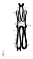
- Figure 3 is a computer-generated analysis of the structure in Figure 2 illustrating the stress/strain distribution of the compressed stent.
- Figure 4 is a perspective view of the stent in Figure 1 in the expanded state.
- Figure 5 is an enlarged partial top view of Figure 4 .
- Figure 6 is a perspective view of a stent portion of one embodiment of the present invention in the compressed state.
- Figure 7 is an enlarged partial top view of Figure 6 .
- Figure 8 a computer-generated analysis of the structure in Figure 7 illustrating the stress/strain distribution of the compressed stent.
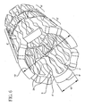
- Figure 9 is a perspective view of the stent in Figure 6 in the expanded state.
- Figure 10 is an enlarged partial top view of Figure 9 .
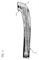
- Figure 11 is an enlarged top view of a computer-generated analysis of a strut section from a conventional stent illustrating the stress/strain distribution when the stent is exposed to an external force.
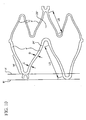
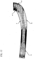
- Figure 12 is an enlarged top view of a computer-generated analysis of a strut section illustrating the stress/strain distribution of a stent having narrowing struts without reverse curvature when the stent is exposed to an external force.
- Figure 13 is a computer-generated analysis of a strut section from the structure in Figure 12 illustrating optimal stress/strain distribution of a stent having narrowing struts with reverse curvature when the stent is exposed to an external force.
- the present invention is preferably used with self-expanding stents, but is not limited to applications involving only self-expanding stents.
- the following detailed description will describe embodiments involving self-expanding stents, however, variations of the invention may be used with balloon-expandable stents and the like.
- Self-expanding stents may be delivered to the deployment site using a delivery catheter system balloon catheter.
- the self-expanding stent is typically placed within a tube located at the distal end of the catheter that places physical limitations on the stent.
- the tube places physical limitations on the stent and retains the stent in its compressed state until it reaches the deployment site. It is desirable to compress the stent to its smallest possible diameter to minimize the profile of the delivery system. This minimized profile allows the delivery system to navigate the stent through narrow restrictions, where ultimately the stent is deployed at the desired site.
- Figures 1 illustrates a conventional stent 2 in the compressed state.
- Conventional stent 2 includes serpentine sections 6 having struts 4 and loops 8.
- the stent has an outside diameter 10 and an inside diameter 14.
- the largest circumferential width 12 of a loop 8 and the adjoining struts 4 as shown in Figure 1 determines the extent to which the stent may be compressed as measured by outside diameter 10.
- the adjacent sets of loop 8 and adjoining struts 4 may or may not make contact with each other.
- An example of adjacent sets of loop and adjoining struts in contact with each other is shown at contact site 16. If contact is made, the interference of the adjacent sets of loop 8 and adjoining struts 4 prevent further reduction in the outside diameter 10 of the stent. Accordingly, the extent to which a conventional stent can be compressed is limited by the contact or interference between the bowed regions 18 of adjacent sets of loop 8 and adjoining struts 4.
- FIG. 2 illustrates a fully compressed cell 20 of a conventional stent.
- cell 20 comprises two serpentine sections 6 extending in the circumferential direction.
- Cell 20 has a longitudinal length "L” between the apexes of interior loops 8 of serpentine sections 6.
- the apexes of adjacent loops 8 on the left-hand side of the cell are aligned along an axis "A”.
- Struts 4 on the left-hand side of the cell have a uniform strut length denoted as "LS".
- left-hand side serpentine section 6 of cell 20 has uniform strut lengths "LS" and loop apexes commonly aligned along axis "A" the largest circumferential widths 12 of adjacent sets of loop 8 and adjoining struts 4 are aligned and form contact site 16 which prevents further circumferential compression of cell 20.
- Figure 3 illustrates a computer-generated analysis of associated stress/strain imparted on a conventional stent when it is compressed.
- the highest levels of stress/strain are concentrated in the outside portions of loops 8 and contact sites 16 between adjacent struts 4.
- the portions of the stent subjected to the highest levels of stress/strain may permanently deform if the stress/strain levels exceed the elastic limits of the stent material. If any portion of the stent becomes permanently deformed, the stent may not fully expand when deployed. It will be understood that the loop portions of the stent are more susceptible to deformation than the strut portions when subjected to high levels of stress/strain.
- the strut portions of the stent can better accommodate high concentrations of stress/strain. This is because the portions of the stent that can withstand higher levels of stress/strain are in the direction of material rolling.
- the direction of material rolling means the direction of the stent that exhibits the highest strength, either due to material orientation or manufacturing direction of the stent, for example as in the rolling or calendaring of a flat sheet of metal.
- the conventional stent as illustrated in Figure 4 has an outside diameter 22.
- the length "LS" of the struts 4 determines the extent to which the stent will expand.
- Figure 5 illustrates a cell 20 of the expanded conventional stent to further demonstrate that the stent's expanded diameter is restricted by the struts length "LS". It will be understood that the longer the strut length "LS,” the longer the distance between adjacent loops 8 as measured along axis A when the stent is expanded. Thus, a stent having cells 20 with longer strut length "LS" will have greater radial expansion than a stent having cells with shorter strut length "LS.”
- Figure 6 illustrates a stent utilizing features of the present invention.
- the present invention is not limited to the structure of the stent shown in Figure 6 , and can be used with any stent structure that contains a serpentine section of any size or number of loops and struts.
- stent 2' is in the compressed state. Due to the modified strut structure 4', the circumferential width 12' of each loop 8' and adjoining struts 4' is reduced relative to that of the conventional stent shown in Figures 1-3 . Accordingly, the outside diameter 10' of stent 2' is also reduced relative to that of the conventional stent of Figures 1-3 .
- Figure 7 illustrates a cell 20' of a stent of the present invention in a compressed state.
- the curved strut when the stent is compressed will straighten and the largest circumferential width 12' formed by of each set of loop 8' and adjoining struts 4' will be significantly reduced compared to a conventional stent having bowed regions 18 as shown in Figures 1-3 . Therefore, the outside diameter of the stent 2' in the compressed state is significantly less than the outside diameter of the conventional stent 2 in the compressed state.
- the outside diameter of the stent 2' in the compressed state decreased from 1.9 mm for the conventional stent to 1.3 mm for the modified stent with all other testing parameters being equal.
- the conventional stent has an expanded to compressed outside diameter ratio of up to about 5:1.
- the various embodiments of the stent of the present invention can provide an expansion to compression ratio of about 7:1. Again, this modification can be used in any stent design.
- the invention is not limited to these exemplary stent structures. Further optimization is achieved in stent 2' as described below.
- FIG. 2 A comparison of Figure 2 and Figure 7 illustrates how optimization of the strut length "LS" can be achieved to increase the expanded stent diameter of the stent 2' without increasing either the stress/strain or the compressed diameter of the stent.
- the adjacent struts 4 have the same strut length LS. Accordingly, the largest circumferential width 12 of adjacent loops 8 is aligned with each other and interferes with each other when the stent is fully compressed. This configuration in a conventional stent limits the possibility of further reducing the compressed stent's outside diameter.
- the adjacent struts 4' having varying lengths "LS'" such that the largest circumferential width 12' of one set of loop 8' and adjoining struts 4' will be offset from the largest circumferential width 12' of the adjacent sets of loop 8' and struts 4'.
- This is further shown by the axially offset positions of the apexes of adjacent loops 8' of stent 2'.
- the apexes of adjacent loops 8' now fall along axis "A"' and axis "B,” respectively.
- This modification provides a decreased outside diameter of the stent in the compressed state because the largest circumferential widths of adjacent sets of loop 8' and adjoining struts 4' no longer interfere with each other and an increased expanded diameter because some of the struts 4' have been lengthened.
- the increased and varied strut lengths "LS" can also result in an optimization of the area within cell 20'.
- the lengths "LS" of the struts adjoining the interior loop of serpentine section 6' forming the left-hand side of cell 20' can be increased to laterally offset the interior loop 8' within cell 20'.
- interior loop 12' is axially offset within cell 20' such that the largest circumferential width 12' of the interior set of loop 8' and adjoining struts 4' is not laterally aligned with the largest circumferential width of adjacent sets of loop 8' and adjoining struts 4'.
- the cell 20' of the embodiment of the present invention shown in Figure 7 will have a much shorter length "L" than that of the conventional stent as shown in Figure 2 .
- This in turn, further allows the compressed stent of the present invention to have a reduced outside diameter compared to the compressed conventional stent illustrated in Figure 1 .
- Figure 8 illustrates a computer generated analysis of the stress/strain imparted on a portion of stent 2' when it is compressed.
- the high stress/strain levels of the conventional stent are concentrated in the loop portions 8 of the stent. Since the loop portions of the stent have the lowest elastic limits, this can lead to permanent deformation of the stent.
- the stress/strain levels imparted on the stent of the present invention were significantly reduced.
- the highest concentrations of stress/strain were redistributed from the loops 8' to the adjoining struts 4', which can accommodate higher stress/strain loads without deforming.
- Various features of the stent of the present invention may contribute to the redistribution of stress/strain loads from the loop portions to the strut portions of the stent.
- the reverse direction curvature design of the struts 4' provide the struts 4' with increased flexibility compared to the loop portions 8 of stent 2. According to this design, the greatest flexibility of strut 4' is at the junction in the mid-section of the stent where opposing curved portions 24' join together. Therefore, when stent 2' is compressed the highest levels of stress/strain will be redistributed from the loop portions toward the strut portions.
- the properties of the material forming the loop 8' and connecting struts 4' can be varied to redistribute the stress/strain to the strut portions of the stent.
- the high levels of stress/strain will be concentrated in the loop portions at areas M. If radial forces exceeding the elastic limit of the stent are applied to stent when compressing the stent to the catheter balloon, the stent will be permanently deformed and will not fully expand when deployed.
- Figure 9 illustrates stent 2' with the reverse direction curvature strut design in the expanded state. Outside diameter 22' is maximized by increasing strut length "LS", as previously discussed, without compromising the compressed stent diameter or increasing stress/strain. The longer strut length "LS" allows a larger expanded outside diameter of the stent and a smaller compressed diameter than a conventional stent.
- FIG 10 illustrates a portion of stent 2' in the expanded state.
- Strut 4' contains the reverse strut bend design.
- Arcuate sections 24' are facing opposite each other and become more curved when expanded as compared to its straighter configuration when strut 4' is compressed.
- the strut 4' is wider at its ends than its mid-section. See, for example, that strut 4' is wider at location "C” than at location "D". This reduced width assists in transferring the stress/strain distribution.
- the loops 8' of stent 2' are made wider than attached struts to further transfer maximal strains encountered by the stent to more suitable parts of the stent, namely the strut sections.
Landscapes
- Health & Medical Sciences (AREA)
- Engineering & Computer Science (AREA)
- Biomedical Technology (AREA)
- Heart & Thoracic Surgery (AREA)
- Life Sciences & Earth Sciences (AREA)
- Cardiology (AREA)
- Oral & Maxillofacial Surgery (AREA)
- Transplantation (AREA)
- Physics & Mathematics (AREA)
- Vascular Medicine (AREA)
- Optics & Photonics (AREA)
- Animal Behavior & Ethology (AREA)
- General Health & Medical Sciences (AREA)
- Public Health (AREA)
- Veterinary Medicine (AREA)
- Media Introduction/Drainage Providing Device (AREA)
- Prostheses (AREA)
Claims (8)
- Stent (2') comprenant :une pluralité de bandes circonférentielles interconnectées définissant une structure cylindrique avec un axe longitudinal ;chacune des bandes circonférentielles présentant un motif généralement en serpentin (6') et comprenant une pluralité d'entretoises (4') et une pluralité de boucles (8'), dans lequel chaque extrémité d'une entretoise (4') est couplée à une extrémité d'une boucle (8') ; etau moins l'une des bandes circonférentielles présentant au moins deux entretoises (4') comprenant une pluralité de sections arquées (24') ; etchaque section arquée (24') dans l'entretoise présentant une courbure opposée à celle d'une section arquée adjacente (24') dans l'entretoise, dans lequel la pluralité de sections arquées (24') dans l'entretoise (4') se dresse et s'étend sensiblement lorsque le stent (2') est comprimécaractérisé en ce quechaque entretoise (4') avec des sections arquées (24') présente une superficie de section qui est plus grande sur les extrémités de l'entretoise que dans la section médiane de l'entretoise (4') ; etdes entretoises adjacentes (4') possèdent des longueurs variables pour produire des positions de décalage axial de boucles adjacentes (8') etla largeur de la boucle (8') est supérieure à la largeur de l'entretoise (4').
- Stent selon la revendication 1, dans lequel ledit stent est à autoexpansion.
- Stent selon la revendication 1, dans lequel ledit stent est expansible sur ballonnet.
- Stent selon la revendication 2, dans lequel le stent (2') présente un rapport entre le diamètre extérieur développé et le diamètre extérieur comprimé supérieur à environ 5:1.
- Stent selon la revendication 2, dans lequel le stent (2') présente un rapport entre le diamètre extérieur développé et le diamètre extérieur comprimé d'environ 7:1.
- Stent selon la revendication 1, dans lequel la contrainte maximale communiquée au stent (2'), lorsque le stent (2') est comprimé, est distribuée vers la section médiane des entretoises (2').
- Stent selon la revendication 1, dans lequel ladite au moins une bande circonférentielle comprend au moins un ensemble de deux entretoises (4') avec des sections arquées (24') couplées aux extrémités d'une boucle (8'), ledit ensemble de boucle et d'entretoises présentant une largeur circonférentielle maximale lorsque le stent (2') est comprimé, la largeur circonférentielle maximale de chaque ensemble de boucle et d'entretoises étant décalée le long de l'axe longitudinal depuis les largeurs circonférentielles maximales d'ensembles adjacents de boucle et d'entretoises lorsque le stent (2') est comprimé.
- Stent selon l'une quelconque des revendications 1 à 7, dans lequel la structure cylindrique définit une pluralité de cellules (20'), chacune de la pluralité de cellules (20') comprenant :une première section circonférentielle présentant un motif généralement en serpentin (6') et comprenant une pluralité d'entretoises (4') et au moins une boucle (8'), les entretoises (4') et les boucles (8') formant au moins un ensemble de deux entretoises couplées aux extrémités d'une boucle (8') ;une seconde section circonférentielle présentant un motif généralement en serpentin (6') et comprenant une pluralité d'entretoises (4') et au moins une boucle (8') ;et au moins l'un des ensembles de la première section circonférentielle ayant deux entretoises (4') comprenant une pluralité de sections arquées (24').
Applications Claiming Priority (2)
| Application Number | Priority Date | Filing Date | Title |
|---|---|---|---|
| US10/864,685 US7763064B2 (en) | 2004-06-08 | 2004-06-08 | Stent having struts with reverse direction curvature |
| PCT/IB2005/001569 WO2005120394A2 (fr) | 2004-06-08 | 2005-06-03 | Stent pourvu d'entretoises presentant des courbures en sens inverse |
Publications (3)
| Publication Number | Publication Date |
|---|---|
| EP1753368A2 EP1753368A2 (fr) | 2007-02-21 |
| EP1753368A4 EP1753368A4 (fr) | 2008-05-14 |
| EP1753368B1 true EP1753368B1 (fr) | 2013-08-07 |
Family
ID=35450043
Family Applications (1)
| Application Number | Title | Priority Date | Filing Date |
|---|---|---|---|
| EP05751740.1A Expired - Lifetime EP1753368B1 (fr) | 2004-06-08 | 2005-06-03 | Stent pourvu d'entretoises presentant des courbures en sens inverse |
Country Status (8)
| Country | Link |
|---|---|
| US (1) | US7763064B2 (fr) |
| EP (1) | EP1753368B1 (fr) |
| JP (1) | JP4580987B2 (fr) |
| AU (1) | AU2005251525B2 (fr) |
| CA (1) | CA2567302C (fr) |
| ES (1) | ES2425841T3 (fr) |
| IL (1) | IL179506A (fr) |
| WO (1) | WO2005120394A2 (fr) |
Families Citing this family (40)
| Publication number | Priority date | Publication date | Assignee | Title |
|---|---|---|---|---|
| US8496699B2 (en) * | 2000-03-01 | 2013-07-30 | Medinol Ltd. | Longitudinally flexible stent |
| US8202312B2 (en) * | 2000-03-01 | 2012-06-19 | Medinol Ltd. | Longitudinally flexible stent |
| US6723119B2 (en) * | 2000-03-01 | 2004-04-20 | Medinol Ltd. | Longitudinally flexible stent |
| US7141062B1 (en) * | 2000-03-01 | 2006-11-28 | Medinol, Ltd. | Longitudinally flexible stent |
| US7828835B2 (en) * | 2000-03-01 | 2010-11-09 | Medinol Ltd. | Longitudinally flexible stent |
| US8920487B1 (en) | 2000-03-01 | 2014-12-30 | Medinol Ltd. | Longitudinally flexible stent |
| US7758627B2 (en) * | 2000-03-01 | 2010-07-20 | Medinol, Ltd. | Longitudinally flexible stent |
| US7621947B2 (en) * | 2000-03-01 | 2009-11-24 | Medinol, Ltd. | Longitudinally flexible stent |
| EP1621158A1 (fr) * | 2004-07-28 | 2006-02-01 | Cordis Corporation | Prothèse à profil réduit pour anévrisme aortique abdominal |
| US7803180B2 (en) | 2005-04-04 | 2010-09-28 | Flexible Stenting Solutions, Inc. | Flexible stent |
| US20060271170A1 (en) * | 2005-05-31 | 2006-11-30 | Gale David C | Stent with flexible sections in high strain regions |
| US8298278B2 (en) * | 2006-03-07 | 2012-10-30 | Boston Scientific Scimed, Inc. | Bifurcated stent with improvement securement |
| US8550344B2 (en) * | 2006-06-16 | 2013-10-08 | The Invention Science Fund I, Llc | Specialty stents with flow control features or the like |
| US7818084B2 (en) * | 2006-06-16 | 2010-10-19 | The Invention Science Fund, I, LLC | Methods and systems for making a blood vessel sleeve |
| US8551155B2 (en) * | 2006-06-16 | 2013-10-08 | The Invention Science Fund I, Llc | Stent customization system and method |
| US8478437B2 (en) * | 2006-06-16 | 2013-07-02 | The Invention Science Fund I, Llc | Methods and systems for making a blood vessel sleeve |
| US8147537B2 (en) * | 2006-06-16 | 2012-04-03 | The Invention Science Fund I, Llc | Rapid-prototyped custom-fitted blood vessel sleeve |
| US20090024152A1 (en) * | 2007-07-17 | 2009-01-22 | Searete Llc, A Limited Liability Corporation Of The State Of Delaware | Custom-fitted blood vessel sleeve |
| US8163003B2 (en) | 2006-06-16 | 2012-04-24 | The Invention Science Fund I, Llc | Active blood vessel sleeve methods and systems |
| US8095382B2 (en) * | 2006-06-16 | 2012-01-10 | The Invention Science Fund I, Llc | Methods and systems for specifying a blood vessel sleeve |
| GB2463842A (en) * | 2007-07-17 | 2010-03-31 | Searete Llc | Methods and systems for making a blood vessel sleeve |
| US7988723B2 (en) | 2007-08-02 | 2011-08-02 | Flexible Stenting Solutions, Inc. | Flexible stent |
| US8414638B2 (en) * | 2008-03-12 | 2013-04-09 | Abbott Cardiovascular Systems Inc. | Method for fabricating a polymer stent with break-away links for enhanced stent retenton |
| CA3272239A1 (en) | 2008-06-06 | 2025-10-28 | Edwards Lifesciences Corporation | Low profile transcatheter heart valve |
| US9149376B2 (en) | 2008-10-06 | 2015-10-06 | Cordis Corporation | Reconstrainable stent delivery system |
| US9211123B2 (en) * | 2009-12-31 | 2015-12-15 | Cook Medical Technologies Llc | Intraluminal occlusion devices and methods of blocking the entry of fluid into bodily passages |
| US9028540B2 (en) | 2011-03-25 | 2015-05-12 | Covidien Lp | Vascular stent with improved vessel wall apposition |
| US8577693B2 (en) | 2011-07-13 | 2013-11-05 | The Invention Science Fund I, Llc | Specialty stents with flow control features or the like |
| US10105067B2 (en) | 2011-09-01 | 2018-10-23 | Microtech Medical Technologies Ltd. | Method of detecting portal and/or hepatic pressure and a portal hypertension monitoring system |
| EP2849688B1 (fr) | 2012-05-14 | 2023-08-23 | C. R. Bard, Inc. | Endoprothèse uniformément extensible |
| US9254205B2 (en) | 2012-09-27 | 2016-02-09 | Covidien Lp | Vascular stent with improved vessel wall apposition |
| USD723165S1 (en) | 2013-03-12 | 2015-02-24 | C. R. Bard, Inc. | Stent |
| DE102014016588A1 (de) * | 2014-11-11 | 2016-05-12 | medicut Stent Technology GmbH | Stentprothese |
| US9956099B2 (en) | 2015-12-17 | 2018-05-01 | Abbott Cardiovascular Systems Inc. | Thin-walled scaffolds having reduced crimp profile and carrying radiopaque markers |
| JP7059182B2 (ja) * | 2015-12-17 | 2022-04-25 | アボット カーディオヴァスキュラー システムズ インコーポレイテッド | 薄肉スキャフォールド |
| CN110314024B (zh) * | 2019-06-26 | 2021-11-05 | 北京工业大学 | 一种适形贴壁血管内支架 |
| US12478488B2 (en) | 2020-02-19 | 2025-11-25 | Medinol Ltd. | Helical stent with enhanced crimping |
| US12150877B1 (en) | 2020-09-02 | 2024-11-26 | Starlight Cardiovascular, Inc. | Devices and methods for maintaining a patent ductus arteriosus |
| US20250025321A1 (en) | 2021-06-17 | 2025-01-23 | Starlight Cardiovascular, Inc. | Ductus arteriosus and septal conduit implants and related delivery systems and methods |
| WO2024222718A1 (fr) * | 2023-04-26 | 2024-10-31 | 心擎医疗(苏州)股份有限公司 | Pompe de cathéter |
Family Cites Families (109)
| Publication number | Priority date | Publication date | Assignee | Title |
|---|---|---|---|---|
| US5037377A (en) | 1984-11-28 | 1991-08-06 | Medtronic, Inc. | Means for improving biocompatibility of implants, particularly of vascular grafts |
| US4755593A (en) | 1985-07-24 | 1988-07-05 | Lauren Mark D | Novel biomaterial of cross-linked peritoneal tissue |
| US5102417A (en) | 1985-11-07 | 1992-04-07 | Expandable Grafts Partnership | Expandable intraluminal graft, and method and apparatus for implanting an expandable intraluminal graft |
| US4733665C2 (en) | 1985-11-07 | 2002-01-29 | Expandable Grafts Partnership | Expandable intraluminal graft and method and apparatus for implanting an expandable intraluminal graft |
| US5133732A (en) | 1987-10-19 | 1992-07-28 | Medtronic, Inc. | Intravascular stent |
| US4886062A (en) | 1987-10-19 | 1989-12-12 | Medtronic, Inc. | Intravascular radially expandable stent and method of implant |
| CA2026604A1 (fr) | 1989-10-02 | 1991-04-03 | Rodney G. Wolff | Drain articule |
| CA2380683C (fr) | 1991-10-28 | 2006-08-08 | Advanced Cardiovascular Systems, Inc. | Empreintes extensibles et leur methode de fabrication |
| US5510077A (en) | 1992-03-19 | 1996-04-23 | Dinh; Thomas Q. | Method of making an intraluminal stent |
| US5571166A (en) | 1992-03-19 | 1996-11-05 | Medtronic, Inc. | Method of making an intraluminal stent |
| US5591224A (en) | 1992-03-19 | 1997-01-07 | Medtronic, Inc. | Bioelastomeric stent |
| EP0566245B1 (fr) | 1992-03-19 | 1999-10-06 | Medtronic, Inc. | Dilatateur intraluminal |
| BE1006440A3 (fr) | 1992-12-21 | 1994-08-30 | Dereume Jean Pierre Georges Em | Endoprothese luminale et son procede de preparation. |
| US5464650A (en) | 1993-04-26 | 1995-11-07 | Medtronic, Inc. | Intravascular stent and method |
| DE69330132T2 (de) | 1993-07-23 | 2001-11-15 | Cook Inc., Bloomington | Flexibler stent mit einer aus einem materialbogen geformten konfiguration |
| US5609627A (en) | 1994-02-09 | 1997-03-11 | Boston Scientific Technology, Inc. | Method for delivering a bifurcated endoluminal prosthesis |
| US5733303A (en) | 1994-03-17 | 1998-03-31 | Medinol Ltd. | Flexible expandable stent |
| US5595571A (en) | 1994-04-18 | 1997-01-21 | Hancock Jaffe Laboratories | Biological material pre-fixation treatment |
| US5693085A (en) | 1994-04-29 | 1997-12-02 | Scimed Life Systems, Inc. | Stent with collagen |
| US5554181A (en) | 1994-05-04 | 1996-09-10 | Regents Of The University Of Minnesota | Stent |
| DE4418336A1 (de) | 1994-05-26 | 1995-11-30 | Angiomed Ag | Stent |
| US5836964A (en) | 1996-10-30 | 1998-11-17 | Medinol Ltd. | Stent fabrication method |
| CA2163824C (fr) | 1994-11-28 | 2000-06-20 | Richard J. Saunders | Methode et appareil pour la coupe directe au laser, d'extenseurs metalliques |
| US5575818A (en) | 1995-02-14 | 1996-11-19 | Corvita Corporation | Endovascular stent with locking ring |
| EP1163889B1 (fr) | 1995-03-01 | 2008-05-14 | Boston Scientific Scimed, Inc. | Extenseur dilatable a flexibilite longitudinale amelioree |
| US7204848B1 (en) | 1995-03-01 | 2007-04-17 | Boston Scientific Scimed, Inc. | Longitudinally flexible expandable stent |
| US6896696B2 (en) | 1998-11-20 | 2005-05-24 | Scimed Life Systems, Inc. | Flexible and expandable stent |
| DE19512066A1 (de) | 1995-04-01 | 1996-11-28 | Variomed Ag | Stütze (Stent, Prothese) für kanalikuläre Körperstrukturen, z. B. Blutgefäße, Gallengänge, Speise- und Luftröhre |
| KR100325267B1 (ko) | 1995-04-26 | 2003-10-11 | 메디놀 리미티드 | 관절성 스텐트 |
| US6602281B1 (en) | 1995-06-05 | 2003-08-05 | Avantec Vascular Corporation | Radially expansible vessel scaffold having beams and expansion joints |
| DE19530835A1 (de) | 1995-08-22 | 1997-02-27 | Emitec Emissionstechnologie | Verfahren zum Herstellen eines Wabenkörpers unter Verwendung schichtartig aufgebauter Bleche mit Lotmaterial |
| US5865723A (en) | 1995-12-29 | 1999-02-02 | Ramus Medical Technologies | Method and apparatus for forming vascular prostheses |
| US5843117A (en) | 1996-02-14 | 1998-12-01 | Inflow Dynamics Inc. | Implantable vascular and endoluminal stents and process of fabricating the same |
| DE69729137T2 (de) | 1996-03-10 | 2005-05-12 | Terumo K.K. | Stent zur Implantation |
| US5713949A (en) | 1996-08-06 | 1998-02-03 | Jayaraman; Swaminathan | Microporous covered stents and method of coating |
| US5922021A (en) | 1996-04-26 | 1999-07-13 | Jang; G. David | Intravascular stent |
| US5922020A (en) | 1996-08-02 | 1999-07-13 | Localmed, Inc. | Tubular prosthesis having improved expansion and imaging characteristics |
| US5807404A (en) | 1996-09-19 | 1998-09-15 | Medinol Ltd. | Stent with variable features to optimize support and method of making such stent |
| US6027527A (en) | 1996-12-06 | 2000-02-22 | Piolax Inc. | Stent |
| US5906759A (en) | 1996-12-26 | 1999-05-25 | Medinol Ltd. | Stent forming apparatus with stent deforming blades |
| FR2758253B1 (fr) | 1997-01-10 | 1999-04-02 | Nycomed Lab Sa | Dispositif implantable pour le traitement d'un conduit corporel |
| US5925061A (en) | 1997-01-13 | 1999-07-20 | Gore Enterprise Holdings, Inc. | Low profile vascular stent |
| DE29702671U1 (de) | 1997-02-17 | 1997-04-10 | Jomed Implantate GmbH, 72414 Rangendingen | Stent |
| DE19717475C1 (de) | 1997-04-25 | 1998-09-03 | Heraeus Gmbh W C | Radial aufweitbare Stützvorrichtung |
| US5855597A (en) | 1997-05-07 | 1999-01-05 | Iowa-India Investments Co. Limited | Stent valve and stent graft for percutaneous surgery |
| DE29708879U1 (de) | 1997-05-20 | 1997-07-31 | Jomed Implantate GmbH, 72414 Rangendingen | Koronarer Stent |
| US5913895A (en) | 1997-06-02 | 1999-06-22 | Isostent, Inc. | Intravascular stent with enhanced rigidity strut members |
| US5746691A (en) | 1997-06-06 | 1998-05-05 | Global Therapeutics, Inc. | Method for polishing surgical stents |
| EP0884029B1 (fr) * | 1997-06-13 | 2004-12-22 | Gary J. Becker | Endoprothèse intraluminale extensible |
| US5855600A (en) | 1997-08-01 | 1999-01-05 | Inflow Dynamics Inc. | Flexible implantable stent with composite design |
| US6165195A (en) | 1997-08-13 | 2000-12-26 | Advanced Cardiovascylar Systems, Inc. | Stent and catheter assembly and method for treating bifurcations |
| DE69838256T2 (de) | 1997-09-24 | 2008-05-15 | Med Institute, Inc., West Lafayette | Radial aufweitbarer stent |
| US6042606A (en) * | 1997-09-29 | 2000-03-28 | Cook Incorporated | Radially expandable non-axially contracting surgical stent |
| US6013091A (en) | 1997-10-09 | 2000-01-11 | Scimed Life Systems, Inc. | Stent configurations |
| US6224625B1 (en) | 1997-10-27 | 2001-05-01 | Iowa-India Investments Company Limited | Low profile highly expandable stent |
| NO311781B1 (no) | 1997-11-13 | 2002-01-28 | Medinol Ltd | Flerlags-stenter av metall |
| US5997973A (en) | 1997-11-18 | 1999-12-07 | Hughes Electronics Corporation | Articulating thermal membrane with integral hinges |
| DE19753123B4 (de) | 1997-11-29 | 2006-11-09 | B. Braun Melsungen Ag | Gefäßstütze |
| US6190406B1 (en) | 1998-01-09 | 2001-02-20 | Nitinal Development Corporation | Intravascular stent having tapered struts |
| US6179868B1 (en) | 1998-03-27 | 2001-01-30 | Janet Burpee | Stent with reduced shortening |
| US6132461A (en) | 1998-03-27 | 2000-10-17 | Intratherapeutics, Inc. | Stent with dual support structure |
| US6241762B1 (en) | 1998-03-30 | 2001-06-05 | Conor Medsystems, Inc. | Expandable medical device with ductile hinges |
| US6264689B1 (en) | 1998-03-31 | 2001-07-24 | Scimed Life Systems, Incorporated | Low profile medical stent |
| US5974652A (en) | 1998-05-05 | 1999-11-02 | Advanced Cardiovascular Systems, Inc. | Method and apparatus for uniformly crimping a stent onto a catheter |
| DE19822157B4 (de) | 1998-05-16 | 2013-01-10 | Abbott Laboratories Vascular Enterprises Ltd. | Radial aufweitbarer Stent zur Implantierung in ein Körpergefäß |
| DE19829702C1 (de) | 1998-07-03 | 2000-03-16 | Heraeus Gmbh W C | Radial aufweitbare Stützvorrichtung V |
| JP4898991B2 (ja) | 1998-08-20 | 2012-03-21 | クック メディカル テクノロジーズ エルエルシー | 被覆付植込式医療装置 |
| US6190403B1 (en) | 1998-11-13 | 2001-02-20 | Cordis Corporation | Low profile radiopaque stent with increased longitudinal flexibility and radial rigidity |
| US20020123789A1 (en) | 1998-12-04 | 2002-09-05 | Francis Ralph T. | Stent cover |
| DE19900411A1 (de) | 1999-01-08 | 2000-07-13 | Lothar Sellin | Stent |
| US6120847A (en) | 1999-01-08 | 2000-09-19 | Scimed Life Systems, Inc. | Surface treatment method for stent coating |
| EP1020166A1 (fr) | 1999-01-12 | 2000-07-19 | Orbus Medical Technologies, Inc. | Endoprothèse intraluminale expansible |
| US6251134B1 (en) | 1999-02-28 | 2001-06-26 | Inflow Dynamics Inc. | Stent with high longitudinal flexibility |
| US6273910B1 (en) | 1999-03-11 | 2001-08-14 | Advanced Cardiovascular Systems, Inc. | Stent with varying strut geometry |
| US6325825B1 (en) * | 1999-04-08 | 2001-12-04 | Cordis Corporation | Stent with variable wall thickness |
| US6273911B1 (en) | 1999-04-22 | 2001-08-14 | Advanced Cardiovascular Systems, Inc. | Variable strength stent |
| US6398802B1 (en) | 1999-06-21 | 2002-06-04 | Scimed Life Systems, Inc. | Low profile delivery system for stent and graft deployment |
| US6312459B1 (en) | 1999-06-30 | 2001-11-06 | Advanced Cardiovascular Systems, Inc. | Stent design for use in small vessels |
| US6540774B1 (en) | 1999-08-31 | 2003-04-01 | Advanced Cardiovascular Systems, Inc. | Stent design with end rings having enhanced strength and radiopacity |
| US6383213B2 (en) | 1999-10-05 | 2002-05-07 | Advanced Cardiovascular Systems, Inc. | Stent and catheter assembly and method for treating bifurcations |
| US6409753B1 (en) * | 1999-10-26 | 2002-06-25 | Scimed Life Systems, Inc. | Flexible stent |
| US6428569B1 (en) | 1999-11-09 | 2002-08-06 | Scimed Life Systems Inc. | Micro structure stent configurations |
| DE19957063A1 (de) | 1999-11-26 | 2001-08-02 | Franz Herbst | Stent und Verfahren zu seiner Herstellung |
| US6280466B1 (en) | 1999-12-03 | 2001-08-28 | Teramed Inc. | Endovascular graft system |
| US6387120B2 (en) | 1999-12-09 | 2002-05-14 | Advanced Cardiovascular Systems, Inc. | Stent and catheter assembly and method for treating bifurcations |
| US7141062B1 (en) | 2000-03-01 | 2006-11-28 | Medinol, Ltd. | Longitudinally flexible stent |
| US6723119B2 (en) | 2000-03-01 | 2004-04-20 | Medinol Ltd. | Longitudinally flexible stent |
| SG86458A1 (en) | 2000-03-01 | 2002-02-19 | Medinol Ltd | Longitudinally flexible stent |
| US20020049490A1 (en) | 2000-04-11 | 2002-04-25 | Pollock David T. | Single-piece endoprosthesis with high expansion ratios |
| US6602282B1 (en) | 2000-05-04 | 2003-08-05 | Avantec Vascular Corporation | Flexible stent structure |
| US6569180B1 (en) | 2000-06-02 | 2003-05-27 | Avantec Vascular Corporation | Catheter having exchangeable balloon |
| US6540775B1 (en) | 2000-06-30 | 2003-04-01 | Cordis Corporation | Ultraflexible open cell stent |
| US6440162B1 (en) | 2000-07-26 | 2002-08-27 | Advanced Cardiovascular Systems, Inc. | Stent having increased scaffolding expandable bar arms |
| US6579310B1 (en) | 2000-08-17 | 2003-06-17 | Advanced Cardiovascular Systems, Inc. | Stent having overlapping struts |
| US6478815B1 (en) | 2000-09-18 | 2002-11-12 | Inflow Dynamics Inc. | Vascular and endoluminal stents |
| US20020116049A1 (en) | 2000-09-22 | 2002-08-22 | Scimed Life Systems, Inc. | Stent |
| US6699278B2 (en) | 2000-09-22 | 2004-03-02 | Cordis Corporation | Stent with optimal strength and radiopacity characteristics |
| US6602226B1 (en) | 2000-10-12 | 2003-08-05 | Scimed Life Systems, Inc. | Low-profile stent delivery system and apparatus |
| US6485508B1 (en) | 2000-10-13 | 2002-11-26 | Mcguinness Colm P. | Low profile stent |
| US7037330B1 (en) | 2000-10-16 | 2006-05-02 | Scimed Life Systems, Inc. | Neurovascular stent and method |
| US6648911B1 (en) | 2000-11-20 | 2003-11-18 | Avantec Vascular Corporation | Method and device for the treatment of vulnerable tissue site |
| US6471980B2 (en) | 2000-12-22 | 2002-10-29 | Avantec Vascular Corporation | Intravascular delivery of mycophenolic acid |
| US6679911B2 (en) | 2001-03-01 | 2004-01-20 | Cordis Corporation | Flexible stent |
| US20020138136A1 (en) | 2001-03-23 | 2002-09-26 | Scimed Life Systems, Inc. | Medical device having radio-opacification and barrier layers |
| US6629994B2 (en) | 2001-06-11 | 2003-10-07 | Advanced Cardiovascular Systems, Inc. | Intravascular stent |
| US6939373B2 (en) | 2003-08-20 | 2005-09-06 | Advanced Cardiovascular Systems, Inc. | Intravascular stent |
| US6673106B2 (en) | 2001-06-14 | 2004-01-06 | Cordis Neurovascular, Inc. | Intravascular stent device |
| US6607554B2 (en) | 2001-06-29 | 2003-08-19 | Advanced Cardiovascular Systems, Inc. | Universal stent link design |
| US6656220B1 (en) | 2002-06-17 | 2003-12-02 | Advanced Cardiovascular Systems, Inc. | Intravascular stent |
-
2004
- 2004-06-08 US US10/864,685 patent/US7763064B2/en not_active Expired - Lifetime
-
2005
- 2005-06-03 CA CA2567302A patent/CA2567302C/fr not_active Expired - Fee Related
- 2005-06-03 EP EP05751740.1A patent/EP1753368B1/fr not_active Expired - Lifetime
- 2005-06-03 JP JP2007526588A patent/JP4580987B2/ja not_active Expired - Lifetime
- 2005-06-03 WO PCT/IB2005/001569 patent/WO2005120394A2/fr not_active Ceased
- 2005-06-03 ES ES05751740T patent/ES2425841T3/es not_active Expired - Lifetime
- 2005-06-03 AU AU2005251525A patent/AU2005251525B2/en not_active Ceased
-
2006
- 2006-11-22 IL IL179506A patent/IL179506A/en active IP Right Grant
Also Published As
| Publication number | Publication date |
|---|---|
| AU2005251525A1 (en) | 2005-12-22 |
| WO2005120394A3 (fr) | 2006-05-18 |
| IL179506A (en) | 2012-03-29 |
| ES2425841T3 (es) | 2013-10-17 |
| CA2567302A1 (fr) | 2005-12-22 |
| WO2005120394A2 (fr) | 2005-12-22 |
| IL179506A0 (en) | 2007-05-15 |
| US20050273157A1 (en) | 2005-12-08 |
| EP1753368A2 (fr) | 2007-02-21 |
| AU2005251525B2 (en) | 2009-05-21 |
| US7763064B2 (en) | 2010-07-27 |
| CA2567302C (fr) | 2012-10-09 |
| EP1753368A4 (fr) | 2008-05-14 |
| JP2008501461A (ja) | 2008-01-24 |
| JP4580987B2 (ja) | 2010-11-17 |
Similar Documents
| Publication | Publication Date | Title |
|---|---|---|
| EP1753368B1 (fr) | Stent pourvu d'entretoises presentant des courbures en sens inverse | |
| EP1998714B1 (fr) | Endoprothèse hélicoïdale résistant à une fracture comprenant des cellules bistables | |
| US8016873B1 (en) | Intravascular hinge stent | |
| US6312460B2 (en) | Intravascular hinge stent | |
| US8317851B2 (en) | Longitudinally flexible stent | |
| US6709453B2 (en) | Longitudinally flexible stent | |
| US8337544B2 (en) | Endoprosthesis having flexible connectors | |
| EP1304090A2 (fr) | Stent flexible longitudinalement | |
| EP1940314B1 (fr) | Endoprothese a geometrie diminuante la contraction | |
| HK1054679A (en) | Longitudinally flexible stent | |
| HK1054678A (en) | Longitudinally flexible stent | |
| HK1054861A (en) | Longitudinally flexible stent |
Legal Events
| Date | Code | Title | Description |
|---|---|---|---|
| PUAI | Public reference made under article 153(3) epc to a published international application that has entered the european phase |
Free format text: ORIGINAL CODE: 0009012 |
|
| 17P | Request for examination filed |
Effective date: 20061123 |
|
| AK | Designated contracting states |
Kind code of ref document: A2 Designated state(s): AT BE BG CH CY CZ DE DK EE ES FI FR GB GR HU IE IS IT LI LT LU MC NL PL PT RO SE SI SK TR |
|
| DAX | Request for extension of the european patent (deleted) | ||
| A4 | Supplementary search report drawn up and despatched |
Effective date: 20080411 |
|
| 17Q | First examination report despatched |
Effective date: 20080902 |
|
| GRAP | Despatch of communication of intention to grant a patent |
Free format text: ORIGINAL CODE: EPIDOSNIGR1 |
|
| GRAS | Grant fee paid |
Free format text: ORIGINAL CODE: EPIDOSNIGR3 |
|
| RAP1 | Party data changed (applicant data changed or rights of an application transferred) |
Owner name: MEDINOL LTD. |
|
| GRAA | (expected) grant |
Free format text: ORIGINAL CODE: 0009210 |
|
| AK | Designated contracting states |
Kind code of ref document: B1 Designated state(s): AT BE BG CH CY CZ DE DK EE ES FI FR GB GR HU IE IS IT LI LT LU MC NL PL PT RO SE SI SK TR |
|
| REG | Reference to a national code |
Ref country code: GB Ref legal event code: FG4D |
|
| REG | Reference to a national code |
Ref country code: AT Ref legal event code: REF Ref document number: 625384 Country of ref document: AT Kind code of ref document: T Effective date: 20130815 Ref country code: CH Ref legal event code: EP Ref country code: CH Ref legal event code: NV Representative=s name: P&TS SA, CH |
|
| REG | Reference to a national code |
Ref country code: IE Ref legal event code: FG4D |
|
| REG | Reference to a national code |
Ref country code: SE Ref legal event code: TRGR |
|
| REG | Reference to a national code |
Ref country code: DE Ref legal event code: R096 Ref document number: 602005040737 Country of ref document: DE Effective date: 20131002 |
|
| REG | Reference to a national code |
Ref country code: ES Ref legal event code: FG2A Ref document number: 2425841 Country of ref document: ES Kind code of ref document: T3 Effective date: 20131017 |
|
| REG | Reference to a national code |
Ref country code: NL Ref legal event code: T3 |
|
| REG | Reference to a national code |
Ref country code: AT Ref legal event code: MK05 Ref document number: 625384 Country of ref document: AT Kind code of ref document: T Effective date: 20130807 |
|
| REG | Reference to a national code |
Ref country code: LT Ref legal event code: MG4D |
|
| PG25 | Lapsed in a contracting state [announced via postgrant information from national office to epo] |
Ref country code: IS Free format text: LAPSE BECAUSE OF FAILURE TO SUBMIT A TRANSLATION OF THE DESCRIPTION OR TO PAY THE FEE WITHIN THE PRESCRIBED TIME-LIMIT Effective date: 20131207 Ref country code: CY Free format text: LAPSE BECAUSE OF FAILURE TO SUBMIT A TRANSLATION OF THE DESCRIPTION OR TO PAY THE FEE WITHIN THE PRESCRIBED TIME-LIMIT Effective date: 20130717 Ref country code: LT Free format text: LAPSE BECAUSE OF FAILURE TO SUBMIT A TRANSLATION OF THE DESCRIPTION OR TO PAY THE FEE WITHIN THE PRESCRIBED TIME-LIMIT Effective date: 20130807 Ref country code: AT Free format text: LAPSE BECAUSE OF FAILURE TO SUBMIT A TRANSLATION OF THE DESCRIPTION OR TO PAY THE FEE WITHIN THE PRESCRIBED TIME-LIMIT Effective date: 20130807 Ref country code: PT Free format text: LAPSE BECAUSE OF FAILURE TO SUBMIT A TRANSLATION OF THE DESCRIPTION OR TO PAY THE FEE WITHIN THE PRESCRIBED TIME-LIMIT Effective date: 20131209 |
|
| PG25 | Lapsed in a contracting state [announced via postgrant information from national office to epo] |
Ref country code: SI Free format text: LAPSE BECAUSE OF FAILURE TO SUBMIT A TRANSLATION OF THE DESCRIPTION OR TO PAY THE FEE WITHIN THE PRESCRIBED TIME-LIMIT Effective date: 20130807 Ref country code: GR Free format text: LAPSE BECAUSE OF FAILURE TO SUBMIT A TRANSLATION OF THE DESCRIPTION OR TO PAY THE FEE WITHIN THE PRESCRIBED TIME-LIMIT Effective date: 20131108 Ref country code: PL Free format text: LAPSE BECAUSE OF FAILURE TO SUBMIT A TRANSLATION OF THE DESCRIPTION OR TO PAY THE FEE WITHIN THE PRESCRIBED TIME-LIMIT Effective date: 20130807 Ref country code: FI Free format text: LAPSE BECAUSE OF FAILURE TO SUBMIT A TRANSLATION OF THE DESCRIPTION OR TO PAY THE FEE WITHIN THE PRESCRIBED TIME-LIMIT Effective date: 20130807 |
|
| PG25 | Lapsed in a contracting state [announced via postgrant information from national office to epo] |
Ref country code: CY Free format text: LAPSE BECAUSE OF FAILURE TO SUBMIT A TRANSLATION OF THE DESCRIPTION OR TO PAY THE FEE WITHIN THE PRESCRIBED TIME-LIMIT Effective date: 20130807 |
|
| PG25 | Lapsed in a contracting state [announced via postgrant information from national office to epo] |
Ref country code: CZ Free format text: LAPSE BECAUSE OF FAILURE TO SUBMIT A TRANSLATION OF THE DESCRIPTION OR TO PAY THE FEE WITHIN THE PRESCRIBED TIME-LIMIT Effective date: 20130807 Ref country code: RO Free format text: LAPSE BECAUSE OF FAILURE TO SUBMIT A TRANSLATION OF THE DESCRIPTION OR TO PAY THE FEE WITHIN THE PRESCRIBED TIME-LIMIT Effective date: 20130807 Ref country code: EE Free format text: LAPSE BECAUSE OF FAILURE TO SUBMIT A TRANSLATION OF THE DESCRIPTION OR TO PAY THE FEE WITHIN THE PRESCRIBED TIME-LIMIT Effective date: 20130807 Ref country code: SK Free format text: LAPSE BECAUSE OF FAILURE TO SUBMIT A TRANSLATION OF THE DESCRIPTION OR TO PAY THE FEE WITHIN THE PRESCRIBED TIME-LIMIT Effective date: 20130807 Ref country code: DK Free format text: LAPSE BECAUSE OF FAILURE TO SUBMIT A TRANSLATION OF THE DESCRIPTION OR TO PAY THE FEE WITHIN THE PRESCRIBED TIME-LIMIT Effective date: 20130807 |
|
| PLBE | No opposition filed within time limit |
Free format text: ORIGINAL CODE: 0009261 |
|
| STAA | Information on the status of an ep patent application or granted ep patent |
Free format text: STATUS: NO OPPOSITION FILED WITHIN TIME LIMIT |
|
| 26N | No opposition filed |
Effective date: 20140508 |
|
| REG | Reference to a national code |
Ref country code: DE Ref legal event code: R097 Ref document number: 602005040737 Country of ref document: DE Effective date: 20140508 |
|
| PG25 | Lapsed in a contracting state [announced via postgrant information from national office to epo] |
Ref country code: LU Free format text: LAPSE BECAUSE OF FAILURE TO SUBMIT A TRANSLATION OF THE DESCRIPTION OR TO PAY THE FEE WITHIN THE PRESCRIBED TIME-LIMIT Effective date: 20140603 Ref country code: MC Free format text: LAPSE BECAUSE OF FAILURE TO SUBMIT A TRANSLATION OF THE DESCRIPTION OR TO PAY THE FEE WITHIN THE PRESCRIBED TIME-LIMIT Effective date: 20130807 |
|
| PG25 | Lapsed in a contracting state [announced via postgrant information from national office to epo] |
Ref country code: BG Free format text: LAPSE BECAUSE OF FAILURE TO SUBMIT A TRANSLATION OF THE DESCRIPTION OR TO PAY THE FEE WITHIN THE PRESCRIBED TIME-LIMIT Effective date: 20130807 |
|
| REG | Reference to a national code |
Ref country code: FR Ref legal event code: PLFP Year of fee payment: 12 |
|
| PG25 | Lapsed in a contracting state [announced via postgrant information from national office to epo] |
Ref country code: TR Free format text: LAPSE BECAUSE OF FAILURE TO SUBMIT A TRANSLATION OF THE DESCRIPTION OR TO PAY THE FEE WITHIN THE PRESCRIBED TIME-LIMIT Effective date: 20130807 Ref country code: HU Free format text: LAPSE BECAUSE OF FAILURE TO SUBMIT A TRANSLATION OF THE DESCRIPTION OR TO PAY THE FEE WITHIN THE PRESCRIBED TIME-LIMIT; INVALID AB INITIO Effective date: 20050603 |
|
| REG | Reference to a national code |
Ref country code: FR Ref legal event code: PLFP Year of fee payment: 13 |
|
| REG | Reference to a national code |
Ref country code: FR Ref legal event code: PLFP Year of fee payment: 14 |
|
| PGFP | Annual fee paid to national office [announced via postgrant information from national office to epo] |
Ref country code: PT Payment date: 20190301 Year of fee payment: 12 Ref country code: SE Payment date: 20190627 Year of fee payment: 15 |
|
| PGFP | Annual fee paid to national office [announced via postgrant information from national office to epo] |
Ref country code: DE Payment date: 20190627 Year of fee payment: 15 |
|
| PGFP | Annual fee paid to national office [announced via postgrant information from national office to epo] |
Ref country code: CH Payment date: 20190702 Year of fee payment: 15 |
|
| REG | Reference to a national code |
Ref country code: DE Ref legal event code: R119 Ref document number: 602005040737 Country of ref document: DE |
|
| REG | Reference to a national code |
Ref country code: CH Ref legal event code: PL |
|
| REG | Reference to a national code |
Ref country code: BE Ref legal event code: MM Effective date: 20200630 |
|
| PG25 | Lapsed in a contracting state [announced via postgrant information from national office to epo] |
Ref country code: CH Free format text: LAPSE BECAUSE OF NON-PAYMENT OF DUE FEES Effective date: 20200630 Ref country code: LI Free format text: LAPSE BECAUSE OF NON-PAYMENT OF DUE FEES Effective date: 20200630 |
|
| PG25 | Lapsed in a contracting state [announced via postgrant information from national office to epo] |
Ref country code: BE Free format text: LAPSE BECAUSE OF NON-PAYMENT OF DUE FEES Effective date: 20200630 Ref country code: DE Free format text: LAPSE BECAUSE OF NON-PAYMENT OF DUE FEES Effective date: 20210101 Ref country code: SE Free format text: LAPSE BECAUSE OF NON-PAYMENT OF DUE FEES Effective date: 20200604 |
|
| REG | Reference to a national code |
Ref country code: SE Ref legal event code: EUG |
|
| P01 | Opt-out of the competence of the unified patent court (upc) registered |
Effective date: 20230510 |
|
| PGFP | Annual fee paid to national office [announced via postgrant information from national office to epo] |
Ref country code: IE Payment date: 20240627 Year of fee payment: 20 |
|
| PGFP | Annual fee paid to national office [announced via postgrant information from national office to epo] |
Ref country code: GB Payment date: 20240627 Year of fee payment: 20 |
|
| PGFP | Annual fee paid to national office [announced via postgrant information from national office to epo] |
Ref country code: NL Payment date: 20240626 Year of fee payment: 20 |
|
| PGFP | Annual fee paid to national office [announced via postgrant information from national office to epo] |
Ref country code: FR Payment date: 20240625 Year of fee payment: 20 |
|
| PGFP | Annual fee paid to national office [announced via postgrant information from national office to epo] |
Ref country code: IT Payment date: 20240619 Year of fee payment: 20 |
|
| PGFP | Annual fee paid to national office [announced via postgrant information from national office to epo] |
Ref country code: ES Payment date: 20240701 Year of fee payment: 20 |
|
| REG | Reference to a national code |
Ref country code: NL Ref legal event code: MK Effective date: 20250602 |
|
| REG | Reference to a national code |
Ref country code: GB Ref legal event code: PE20 Expiry date: 20250602 |
|
| REG | Reference to a national code |
Ref country code: ES Ref legal event code: FD2A Effective date: 20250626 |
|
| PG25 | Lapsed in a contracting state [announced via postgrant information from national office to epo] |
Ref country code: ES Free format text: LAPSE BECAUSE OF EXPIRATION OF PROTECTION Effective date: 20250604 Ref country code: GB Free format text: LAPSE BECAUSE OF EXPIRATION OF PROTECTION Effective date: 20250602 |
|
| REG | Reference to a national code |
Ref country code: IE Ref legal event code: MK9A |
|
| PG25 | Lapsed in a contracting state [announced via postgrant information from national office to epo] |
Ref country code: IE Free format text: LAPSE BECAUSE OF EXPIRATION OF PROTECTION Effective date: 20250603 |