EP1753585B1 - Fastening driving tool with pivotally mounted magazine and magazine therefor - Google Patents
Fastening driving tool with pivotally mounted magazine and magazine therefor Download PDFInfo
- Publication number
- EP1753585B1 EP1753585B1 EP05750249A EP05750249A EP1753585B1 EP 1753585 B1 EP1753585 B1 EP 1753585B1 EP 05750249 A EP05750249 A EP 05750249A EP 05750249 A EP05750249 A EP 05750249A EP 1753585 B1 EP1753585 B1 EP 1753585B1
- Authority
- EP
- European Patent Office
- Prior art keywords
- magazine
- handle
- barrel
- joint
- fixing rod
- Prior art date
- Legal status (The legal status is an assumption and is not a legal conclusion. Google has not performed a legal analysis and makes no representation as to the accuracy of the status listed.)
- Expired - Lifetime
Links
Images


Classifications
-
- B—PERFORMING OPERATIONS; TRANSPORTING
- B25—HAND TOOLS; PORTABLE POWER-DRIVEN TOOLS; MANIPULATORS
- B25C—HAND-HELD NAILING OR STAPLING TOOLS; MANUALLY OPERATED PORTABLE STAPLING TOOLS
- B25C1/00—Hand-held nailing tools; Nail feeding devices
- B25C1/08—Hand-held nailing tools; Nail feeding devices operated by combustion pressure
-
- B—PERFORMING OPERATIONS; TRANSPORTING
- B25—HAND TOOLS; PORTABLE POWER-DRIVEN TOOLS; MANIPULATORS
- B25C—HAND-HELD NAILING OR STAPLING TOOLS; MANUALLY OPERATED PORTABLE STAPLING TOOLS
- B25C1/00—Hand-held nailing tools; Nail feeding devices
- B25C1/08—Hand-held nailing tools; Nail feeding devices operated by combustion pressure
- B25C1/10—Hand-held nailing tools; Nail feeding devices operated by combustion pressure generated by detonation of a cartridge
- B25C1/18—Details and accessories, e.g. splinter guards, spall minimisers
- B25C1/182—Feeding devices
- B25C1/184—Feeding devices for nails
Definitions
- This invention is in the field of fixing equipment, in particular equipment that uses gas or internal combustion motors.
- This equipment operates using the principle of an explosion of an inflammable mixture of gas and air in the motor combustion chamber (formed in part by a cylinder, a cylinder barrel and a cylinder head) to propel a piston for driving a fastening element.
- the motor is fitted inside a casing.
- the casing is fitted inside two shells of a handle, and to the front and rear of which are fitted a handle with a housing for holding a battery to provide electrical power and a means of fitting a removable feeder magazine for the fastening elements. More precisely, to the rear, the motor cylinder head, the casing and the shells of the handle are fitted together using the same bolts.
- the casing which is generally made from a plastic material, is subjected to high levels of compression stress, up to 60% of all the stresses.
- the casing for gas powered fixing equipment already acts as an elastic damper since it manages to stretch a little.
- the magazine therefore must be firmly fixed to the nose or muzzle-bushing of the apparatus in order to maintain a proper supply of the fastening elements. If, however, the front of the apparatus moves (under the action of the forward part of the casing) relative to the rest of the apparatus and the supply end (or output end) of the fastening element magazine moves with it, whilst the other loading end (or input end) of the magazine remains firmly fixed to the handle, the supply of fastening elements into the muzzle bushing of the apparatus may not be correctly performed.
- the invention therefore involves, in the first place, an apparatus according to claim 1.
- the front of the apparatus moves, it can carry with it the feed end of the magazine, since this can also carry with it the other (loading) end of the magazine.
- the freedom of the loading end of the magazine to move on the handle of the equipment means that dimensional compensation can be carried out on assembly.
- the rod is preferably to be mounted so as to pivot against the action of return means.
- the magazine fixing rod on the free end of the handle is cylindrical and mounted so that it pivots around a point on its axis.
- the rod is preferably mounted in a ball and socket joint fitted in the handle of the equipment.
- the socket is preferably mounted in an elastic return sleeve.
- the rod is threaded and bear at its threaded end a thumb wheel for tightening the magazine, preferably through a head on the rod that is arranged so that it comes to rest against the magazine and tightens it against the handle.
- the free end of the handle includes an inclined face arranged so that it cooperates with another inclined face on the magazine. It therefore forms a wedge and moves the magazine to the front of the apparatus so that the feed end is placed against the barrel.
- this thumb wheel also carries out a pushing function.
- the invention also involves a removable feed magazine for fastening elements for the apparatus of the invention according to claim 11.
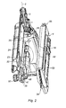
- the fastening apparatus included here therefore has an internal combustion motor, well known throughout the profession and designed to drive a fastening element inside barrel 1 in the apparatus along axis 2 through the nose or muzzle-bushing 3 of the apparatus into which the barrel extends, with the fastening element having previously been transferred into the barrel 1 from the feed magazine 4.
- the drive motor for the apparatus is fitted in a casing, the rear of which is closed off by a ventilation block 6 and the two shells 7, 8 of handle 9.
- Four fixing bolts 10-13 fix together the rear part 14 of casing 5, the block 6 and the handle shells 7, 8.
- the handle shells are each made up of a cut-out framework 15 (16) designed to be pushed against a lateral surface 17 (18) of the casing and at the rear a half-clamp 19 (20) which completes the rear enclosure of the casing 5 by means of the two half clamps connected by a tongue and groove to form a fixing sleeve 21.
- Each handle shell is extended to the rear by means of a component of the handle itself 22 (23) and to the front by a structure 24 for housing an electrical supply battery and by a support structure 25 for the fastening element magazine 4.
- the motor is therefore fitted in the casing 5 which is mounted in the assembly formed by the two shells 7, 8 of the handle 9 to which it is fitted at the rear by bolts 10-13.
- the fastening apparatus has a plane of symmetry passing through axis 2.
- the front mortises and tenons 30, 28 must fit slightly one inside the other due to their transverse dimensions, but not their dimensions parallel to axis 2.
- the axial external length of tenons 30 of the front part 51 of casing 5 is noticeably shorter than the internal axial length of mortises 28 precisely to allow the axial sliding of the tenons in the mortises.
- the annular front walls 31 and rear walls 32 of the front mortise-channels 28 make up the front and rear end-stop components for the front tenons 30 in the casing.
- the front part 51 of the casing is a floating fit in the handle 7-9 and can be made to slide inside it in a direction which is parallel to the drive axis 2 for the fastening elements.
- the shells 22, 23 joined together by bolts 34, 35 are shaped internally to take a spherical housing 36, with one part of the spherical surface in shell 22 and another part of the spherical surface in shell 23.
- the spherical housing 36 opens onto the external surface 37 of shell 22 and to external surface 38 of shell 23 through two conical openings 39, 40, the usefulness of which will soon become apparent.
- the spherical housing 36 extends through a tubular hollow 41 along axis 42, perpendicular to surfaces 37, 38 of the shells of the handles, and which passes through the centre of the housing sphere. Its axial length is smaller than the diameter of housing 36, in the case in point, between a third and a quarter of this diameter, and its diameter is slightly larger than that of the sphere in housing 36, in the case in point, about a quarter more.
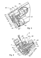
- Housing 36 is holds a ball and socket joint 43 with a through tapped hole 44 crossing axis 42, at rest, and extending along the same axis 42 at rest, and which extends along axis 42 still at rest by means of two small tubular sections 45, 46 which are crossed by the threaded hole 44 and which emerge from the two shells 22, 23 through the conical openings 39 and 40.
- the tubular extensions 45, 46 of ball and socket joint 43 have an external diameter that is slightly less than the small internal diameter of he conical openings 39, 40 with the tubular section 45, protruding outside the shell 22 being axially slightly longer than the other tubular section 46 opposite.
- the small tubular section 46 protruding outside the handle shell 23 is designed to fit inside a corresponding hollow in the magazine.
- a fixing rod 47 here cylindrical, extends into the threaded hole 44.
- the rod 47 carries at one end a support head 48, with its other end 49 being threaded. Onto the threaded end 49 of the rod 47 is screwed a threaded thumb-wheel which also fits into the tubular part 45 of the joint 43 up to an internal back face 51.
- the thumb-wheel 50 When the thumb-wheel 50 is screwed onto the threaded rod 47, with the thumb-wheel against the end face 51 against the tubular part 45 of joint 43, the thumb-wheel constrains the rod by moving the handle shells 22, 23 along axis 42 towards the head 48 and tightens, as will be seen below, the end of magazine 4 against the end face of the tubular portion 46 of joint 43.
- the removable magazine 4 is also made of two shells 52, 53 between which (in a standard manner which is widely known in the trade) is introduced, through a loading end 54, a strip of fixing elements which will then be transferred one at a time through a feed end 55 of the magazine into the barrel 1 of the equipment which is thus fed with fastening elements (here nails).
- the head 48 of the rod is designed to be fitted in an opening in shell 53 of the magazine in order (under the action of thumb-wheel 50 and of the traction caused by screwing it in) that it comes against shell 52 and so tightens the magazine 4 onto the handle 9.
- the magazine 4 is fitted onto handle 9 as follows.
- the loading end 54 of magazine 4 is held flat against surface 38 of the handle shell 23 by fitting the tubular portion 46 of the joint 43 into the hollow 56 in the shell of magazine 52.
- the rod 47 is then slid into opening 57 in the shell 53 of the magazine and through a collar 58 fitted in shell 52 before it is inserted into the threaded hole 44, until its head 48 meets wall 59 of the collar 58 and the threaded portion 49 emerges from the tubular portion 45 of joint 43.
- the thumb-wheel 50 is then screwed onto the threaded end 49 of rod 47 to tighten the head of the rod 48 against the shell of the magazine 52. This therefore tightens magazine 4 against the handle 9, and more precisely, against the end face of the tubular section 46 of the joint 43 whilst the thumbwheel is fitted onto the tubular portion 45.
- the thumb-wheel can be fixed to the joint.
- a small sleeve 60 made of elastomeric material which is compressible and elastic, which is also partly housed in a peripheral tubular hollow 61, along axis 42 at rest, fitted in the joint 43.
- the sleeve is therefore fixed solidly to the joint and may be compressed depending on the alignment of the joint.
- the tubular portion 46 which extends joint 43 from the magazine side is wedged to offer an inclined face 62 which is inclined in a clockwise direction on a transverse plane of the handle perpendicular to the support structure 25, effectively parallel to axis 2 of the apparatus and containing axis 42 (the plane in figure 4 ) the inclination of which is determined in a longitudinal plane of the handle (the plane in figure 5 ).
- the magazine shell 52 is shaped in a corresponding manner to present in opening 57 a face 63 which is inclined in the same manner and which cooperates with the inclined face 62 of the joint and so acts as a wedge.
- the two inclined faces 62, 63 are crossed by the fixing rod 47.
- the advantage to be obtained from fitting the joint in a compressible and elastic sleeve is that it softens the wedge effect and provides a means of returning the joint to its at-rest position for assembly and disassembly of the apparatus.
Landscapes
- Engineering & Computer Science (AREA)
- Chemical & Material Sciences (AREA)
- Combustion & Propulsion (AREA)
- Mechanical Engineering (AREA)
- Portable Nailing Machines And Staplers (AREA)
- Details Of Spanners, Wrenches, And Screw Drivers And Accessories (AREA)
- Automatic Assembly (AREA)
Applications Claiming Priority (2)
| Application Number | Priority Date | Filing Date | Title |
|---|---|---|---|
| FR0405905A FR2871081B1 (fr) | 2004-06-02 | 2004-06-02 | Appareil de fixation d'elements de fixation a moyens de serrage et de placage d'un magasin d'alimentation demontable et magasin d'alimentation pour l'appareil de fixation |
| PCT/IB2005/001495 WO2005118228A1 (en) | 2004-06-02 | 2005-05-27 | Fastening driving tool with pivotally mounted magazine and magazine therefor |
Publications (2)
| Publication Number | Publication Date |
|---|---|
| EP1753585A1 EP1753585A1 (en) | 2007-02-21 |
| EP1753585B1 true EP1753585B1 (en) | 2011-07-06 |
Family
ID=34946480
Family Applications (1)
| Application Number | Title | Priority Date | Filing Date |
|---|---|---|---|
| EP05750249A Expired - Lifetime EP1753585B1 (en) | 2004-06-02 | 2005-05-27 | Fastening driving tool with pivotally mounted magazine and magazine therefor |
Country Status (10)
| Country | Link |
|---|---|
| US (1) | US7600662B2 (da) |
| EP (1) | EP1753585B1 (da) |
| JP (1) | JP4988564B2 (da) |
| AT (1) | ATE515377T1 (da) |
| AU (1) | AU2005249788B2 (da) |
| CA (1) | CA2565038C (da) |
| DK (1) | DK1753585T3 (da) |
| FR (1) | FR2871081B1 (da) |
| NZ (1) | NZ550901A (da) |
| WO (1) | WO2005118228A1 (da) |
Families Citing this family (14)
| Publication number | Priority date | Publication date | Assignee | Title |
|---|---|---|---|---|
| TWI434754B (zh) * | 2007-08-17 | 2014-04-21 | Rexon Ind Corp Ltd | Nailer rotation device |
| CN201389838Y (zh) * | 2009-03-27 | 2010-01-27 | 张汉勤 | 射钉发射装置 |
| US8678261B2 (en) * | 2011-07-08 | 2014-03-25 | Chung-Yi Lee | Position-limiting device and magazine |
| EP2923800A1 (de) * | 2014-03-28 | 2015-09-30 | HILTI Aktiengesellschaft | Pyrotechnisches Eintreibgerät |
| US11325235B2 (en) | 2016-06-28 | 2022-05-10 | Black & Decker, Inc. | Push-on support member for fastening tools |
| US11267114B2 (en) * | 2016-06-29 | 2022-03-08 | Black & Decker, Inc. | Single-motion magazine retention for fastening tools |
| US11279013B2 (en) | 2016-06-30 | 2022-03-22 | Black & Decker, Inc. | Driver rebound plate for a fastening tool |
| US10987790B2 (en) | 2016-06-30 | 2021-04-27 | Black & Decker Inc. | Cordless concrete nailer with improved power take-off mechanism |
| US11400572B2 (en) | 2016-06-30 | 2022-08-02 | Black & Decker, Inc. | Dry-fire bypass for a fastening tool |
| CA2985041C (en) * | 2016-11-09 | 2023-03-14 | Tti (Macao Commercial Offshore) Limited | Gas spring fastener driver |
| US10926385B2 (en) | 2017-02-24 | 2021-02-23 | Black & Decker, Inc. | Contact trip having magnetic filter |
| EP4237201A4 (en) | 2020-10-30 | 2024-12-11 | Milwaukee Electric Tool Corporation | POWERED FASTENER DRIVER |
| US20220134523A1 (en) * | 2020-11-04 | 2022-05-05 | Byron Cowan | Variable Action Floor Nailing Gun |
| AU2022268970B2 (en) * | 2021-05-07 | 2024-11-28 | Kyocera Senco Industrial Tools, Inc. | Gas spring fastener driving tool with removable end cap for performing maintenance or service |
Family Cites Families (16)
| Publication number | Priority date | Publication date | Assignee | Title |
|---|---|---|---|---|
| DE1286469B (de) * | 1966-02-26 | 1969-01-02 | Dieter Haubold Ind Nagelgeraet | Sicherheitseinrichtung an einem mit Druckluft betriebenen Handgeraet zum Eintreiben von Befestigungsmitteln |
| US3437250A (en) * | 1966-04-07 | 1969-04-08 | Fastener Corp | Fastener driving tool |
| US3834602A (en) * | 1973-01-26 | 1974-09-10 | Fastener Corp | Fastener driving tool |
| CA1093753A (en) * | 1978-07-05 | 1981-01-20 | Raymond F. Novak | Electric brad nailer |
| US4389012A (en) * | 1981-04-22 | 1983-06-21 | Duo-Fast Corporation | Fastener tool loading assembly |
| US4570840A (en) * | 1983-01-27 | 1986-02-18 | Bull William T | Nailing gun |
| DE3337278A1 (de) * | 1983-10-13 | 1985-04-25 | Metabowerke GmbH & Co, 7440 Nürtingen | Eintreibgeraet |
| GB2149754A (en) * | 1983-11-14 | 1985-06-19 | Umberto Monacelli | Magazine for fasteners in coiled form |
| US4809849A (en) * | 1986-03-19 | 1989-03-07 | The Fletcher-Terry Company | Stack of asymmetric fasteners and combination thereof with cooperating magazine |
| US4801062A (en) * | 1987-06-18 | 1989-01-31 | Duo-Fast Corporation | Side load magazine for a fastener driving tool |
| US5025968A (en) * | 1989-06-19 | 1991-06-25 | Duo-Fast Corporation | Furniture tool |
| JP3582386B2 (ja) * | 1998-11-20 | 2004-10-27 | マックス株式会社 | ステープル打ち機のステープルマガジン |
| TW424653U (en) * | 1999-10-30 | 2001-03-01 | Jins Industry Corp | Improved structure for nail housing cartridge of nailing gun |
| DE10036078B4 (de) * | 2000-07-25 | 2007-04-05 | Robert Bosch Gmbh | Handwerkzeugmaschine mit einem Handgriff und einer Isoliervorrichtung |
| US6431428B1 (en) * | 2000-10-16 | 2002-08-13 | Jui-Chin Chen | Pneumatic nail gun |
| TWM243329U (en) * | 2003-03-31 | 2004-09-11 | Besco Pneumatic Corp | Improved structure of palm-held hammer |
-
2004
- 2004-06-02 FR FR0405905A patent/FR2871081B1/fr not_active Expired - Fee Related
-
2005
- 2005-05-27 AT AT05750249T patent/ATE515377T1/de not_active IP Right Cessation
- 2005-05-27 CA CA2565038A patent/CA2565038C/en not_active Expired - Fee Related
- 2005-05-27 AU AU2005249788A patent/AU2005249788B2/en not_active Expired
- 2005-05-27 US US11/569,872 patent/US7600662B2/en not_active Expired - Lifetime
- 2005-05-27 DK DK05750249.4T patent/DK1753585T3/da active
- 2005-05-27 JP JP2007514178A patent/JP4988564B2/ja not_active Expired - Fee Related
- 2005-05-27 EP EP05750249A patent/EP1753585B1/en not_active Expired - Lifetime
- 2005-05-27 WO PCT/IB2005/001495 patent/WO2005118228A1/en not_active Ceased
- 2005-05-27 NZ NZ550901A patent/NZ550901A/en not_active IP Right Cessation
Also Published As
| Publication number | Publication date |
|---|---|
| FR2871081B1 (fr) | 2006-08-11 |
| AU2005249788A1 (en) | 2005-12-15 |
| EP1753585A1 (en) | 2007-02-21 |
| CA2565038C (en) | 2010-07-27 |
| JP4988564B2 (ja) | 2012-08-01 |
| CA2565038A1 (en) | 2005-12-15 |
| WO2005118228A1 (en) | 2005-12-15 |
| DK1753585T3 (da) | 2011-10-10 |
| US7600662B2 (en) | 2009-10-13 |
| ATE515377T1 (de) | 2011-07-15 |
| AU2005249788B2 (en) | 2009-04-02 |
| JP2008501537A (ja) | 2008-01-24 |
| US20080283568A1 (en) | 2008-11-20 |
| NZ550901A (en) | 2010-11-26 |
| FR2871081A1 (fr) | 2005-12-09 |
Similar Documents
| Publication | Publication Date | Title |
|---|---|---|
| EP1753585B1 (en) | Fastening driving tool with pivotally mounted magazine and magazine therefor | |
| CN100396211C (zh) | 电动手持工具的可更换手柄 | |
| US7278342B1 (en) | Tool connecting device | |
| US5988653A (en) | Auto-locking bit holding system of a hand tool | |
| AU2003204598A1 (en) | Interchangable magazine for a tool | |
| US20060260446A1 (en) | Tool connecting device | |
| US7980238B2 (en) | Paintball marker with ability to discharge different sized projectiles | |
| CN221048350U (zh) | 用于动力工具的减振结构和带有减振结构的动力工具 | |
| CN102036786B (zh) | 安装键锁插件的工具附件和包括这种工具附件的成套工具 | |
| JP2008511457A (ja) | 燃焼動力式工具のための燃料セル室 | |
| AU2005308143A1 (en) | Drive-in machine | |
| AU727376B2 (en) | Fastener-driving tool having magazine mounted to tool handle by mortise and tenon mounting | |
| KR101197669B1 (ko) | 선회되게 장착되는 매거진을 구비한 패스너 구동 공구와 이를 위한 매거진 | |
| US6564789B1 (en) | BB bullet feeding device of toy gun | |
| WO2005010912A3 (en) | Modular ion source | |
| TW200711793A (en) | Pneumatic ratchet drive tool | |
| CN100571993C (zh) | 前端外壳可移动的气动操纵固定装置 | |
| CN117182844A (zh) | 冲击转动工具 | |
| JP7047446B2 (ja) | 打込み工具 | |
| JP2002036138A (ja) | 釘打機のノーズ部材に対するマガジンの組み付け方法 | |
| CN223917880U (zh) | 一种夹头组件、射钉枪和射钉枪套装 | |
| US20250073881A1 (en) | Hammer assembly for a power tool | |
| KR20220080841A (ko) | 토크렌치 |
Legal Events
| Date | Code | Title | Description |
|---|---|---|---|
| PUAI | Public reference made under article 153(3) epc to a published international application that has entered the european phase |
Free format text: ORIGINAL CODE: 0009012 |
|
| 17P | Request for examination filed |
Effective date: 20061228 |
|
| AK | Designated contracting states |
Kind code of ref document: A1 Designated state(s): AT BE BG CH CY CZ DE DK EE ES FI FR GB GR HU IE IS IT LI LT LU MC NL PL PT RO SE SI SK TR |
|
| DAX | Request for extension of the european patent (deleted) | ||
| RIN1 | Information on inventor provided before grant (corrected) |
Inventor name: MARION, CYRIL Inventor name: TOULOUSE, BRUNO Inventor name: NAYRAC, FREDERIC |
|
| 17Q | First examination report despatched |
Effective date: 20071109 |
|
| RIN1 | Information on inventor provided before grant (corrected) |
Inventor name: MARION, CYRIL Inventor name: NAYRAC, FREDERIC Inventor name: TOULOUSE, BRUNO |
|
| APBK | Appeal reference recorded |
Free format text: ORIGINAL CODE: EPIDOSNREFNE |
|
| APBN | Date of receipt of notice of appeal recorded |
Free format text: ORIGINAL CODE: EPIDOSNNOA2E |
|
| APBR | Date of receipt of statement of grounds of appeal recorded |
Free format text: ORIGINAL CODE: EPIDOSNNOA3E |
|
| APAF | Appeal reference modified |
Free format text: ORIGINAL CODE: EPIDOSCREFNE |
|
| APBT | Appeal procedure closed |
Free format text: ORIGINAL CODE: EPIDOSNNOA9E |
|
| GRAP | Despatch of communication of intention to grant a patent |
Free format text: ORIGINAL CODE: EPIDOSNIGR1 |
|
| GRAS | Grant fee paid |
Free format text: ORIGINAL CODE: EPIDOSNIGR3 |
|
| GRAA | (expected) grant |
Free format text: ORIGINAL CODE: 0009210 |
|
| AK | Designated contracting states |
Kind code of ref document: B1 Designated state(s): AT BE BG CH CY CZ DE DK EE ES FI FR GB GR HU IE IS IT LI LT LU MC NL PL PT RO SE SI SK TR |
|
| REG | Reference to a national code |
Ref country code: GB Ref legal event code: FG4D |
|
| REG | Reference to a national code |
Ref country code: CH Ref legal event code: EP |
|
| REG | Reference to a national code |
Ref country code: IE Ref legal event code: FG4D |
|
| REG | Reference to a national code |
Ref country code: DE Ref legal event code: R096 Ref document number: 602005028878 Country of ref document: DE Effective date: 20110901 |
|
| REG | Reference to a national code |
Ref country code: NL Ref legal event code: T3 |
|
| REG | Reference to a national code |
Ref country code: DK Ref legal event code: T3 |
|
| REG | Reference to a national code |
Ref country code: SE Ref legal event code: TRGR |
|
| PG25 | Lapsed in a contracting state [announced via postgrant information from national office to epo] |
Ref country code: SI Free format text: LAPSE BECAUSE OF FAILURE TO SUBMIT A TRANSLATION OF THE DESCRIPTION OR TO PAY THE FEE WITHIN THE PRESCRIBED TIME-LIMIT Effective date: 20110706 |
|
| REG | Reference to a national code |
Ref country code: AT Ref legal event code: MK05 Ref document number: 515377 Country of ref document: AT Kind code of ref document: T Effective date: 20110706 |
|
| PG25 | Lapsed in a contracting state [announced via postgrant information from national office to epo] |
Ref country code: PT Free format text: LAPSE BECAUSE OF FAILURE TO SUBMIT A TRANSLATION OF THE DESCRIPTION OR TO PAY THE FEE WITHIN THE PRESCRIBED TIME-LIMIT Effective date: 20111107 Ref country code: IS Free format text: LAPSE BECAUSE OF FAILURE TO SUBMIT A TRANSLATION OF THE DESCRIPTION OR TO PAY THE FEE WITHIN THE PRESCRIBED TIME-LIMIT Effective date: 20111106 Ref country code: FI Free format text: LAPSE BECAUSE OF FAILURE TO SUBMIT A TRANSLATION OF THE DESCRIPTION OR TO PAY THE FEE WITHIN THE PRESCRIBED TIME-LIMIT Effective date: 20110706 Ref country code: LT Free format text: LAPSE BECAUSE OF FAILURE TO SUBMIT A TRANSLATION OF THE DESCRIPTION OR TO PAY THE FEE WITHIN THE PRESCRIBED TIME-LIMIT Effective date: 20110706 |
|
| PG25 | Lapsed in a contracting state [announced via postgrant information from national office to epo] |
Ref country code: GR Free format text: LAPSE BECAUSE OF FAILURE TO SUBMIT A TRANSLATION OF THE DESCRIPTION OR TO PAY THE FEE WITHIN THE PRESCRIBED TIME-LIMIT Effective date: 20111007 Ref country code: AT Free format text: LAPSE BECAUSE OF FAILURE TO SUBMIT A TRANSLATION OF THE DESCRIPTION OR TO PAY THE FEE WITHIN THE PRESCRIBED TIME-LIMIT Effective date: 20110706 Ref country code: PL Free format text: LAPSE BECAUSE OF FAILURE TO SUBMIT A TRANSLATION OF THE DESCRIPTION OR TO PAY THE FEE WITHIN THE PRESCRIBED TIME-LIMIT Effective date: 20110706 Ref country code: CY Free format text: LAPSE BECAUSE OF FAILURE TO SUBMIT A TRANSLATION OF THE DESCRIPTION OR TO PAY THE FEE WITHIN THE PRESCRIBED TIME-LIMIT Effective date: 20110706 |
|
| PG25 | Lapsed in a contracting state [announced via postgrant information from national office to epo] |
Ref country code: CZ Free format text: LAPSE BECAUSE OF FAILURE TO SUBMIT A TRANSLATION OF THE DESCRIPTION OR TO PAY THE FEE WITHIN THE PRESCRIBED TIME-LIMIT Effective date: 20110706 Ref country code: SK Free format text: LAPSE BECAUSE OF FAILURE TO SUBMIT A TRANSLATION OF THE DESCRIPTION OR TO PAY THE FEE WITHIN THE PRESCRIBED TIME-LIMIT Effective date: 20110706 |
|
| PLBE | No opposition filed within time limit |
Free format text: ORIGINAL CODE: 0009261 |
|
| STAA | Information on the status of an ep patent application or granted ep patent |
Free format text: STATUS: NO OPPOSITION FILED WITHIN TIME LIMIT |
|
| PG25 | Lapsed in a contracting state [announced via postgrant information from national office to epo] |
Ref country code: IT Free format text: LAPSE BECAUSE OF FAILURE TO SUBMIT A TRANSLATION OF THE DESCRIPTION OR TO PAY THE FEE WITHIN THE PRESCRIBED TIME-LIMIT Effective date: 20110706 Ref country code: EE Free format text: LAPSE BECAUSE OF FAILURE TO SUBMIT A TRANSLATION OF THE DESCRIPTION OR TO PAY THE FEE WITHIN THE PRESCRIBED TIME-LIMIT Effective date: 20110706 Ref country code: RO Free format text: LAPSE BECAUSE OF FAILURE TO SUBMIT A TRANSLATION OF THE DESCRIPTION OR TO PAY THE FEE WITHIN THE PRESCRIBED TIME-LIMIT Effective date: 20110706 |
|
| 26N | No opposition filed |
Effective date: 20120411 |
|
| REG | Reference to a national code |
Ref country code: DE Ref legal event code: R097 Ref document number: 602005028878 Country of ref document: DE Effective date: 20120411 |
|
| PG25 | Lapsed in a contracting state [announced via postgrant information from national office to epo] |
Ref country code: MC Free format text: LAPSE BECAUSE OF NON-PAYMENT OF DUE FEES Effective date: 20120531 |
|
| REG | Reference to a national code |
Ref country code: CH Ref legal event code: PL |
|
| PG25 | Lapsed in a contracting state [announced via postgrant information from national office to epo] |
Ref country code: CH Free format text: LAPSE BECAUSE OF NON-PAYMENT OF DUE FEES Effective date: 20120531 Ref country code: LI Free format text: LAPSE BECAUSE OF NON-PAYMENT OF DUE FEES Effective date: 20120531 |
|
| REG | Reference to a national code |
Ref country code: IE Ref legal event code: MM4A |
|
| PG25 | Lapsed in a contracting state [announced via postgrant information from national office to epo] |
Ref country code: IE Free format text: LAPSE BECAUSE OF NON-PAYMENT OF DUE FEES Effective date: 20120527 Ref country code: ES Free format text: LAPSE BECAUSE OF FAILURE TO SUBMIT A TRANSLATION OF THE DESCRIPTION OR TO PAY THE FEE WITHIN THE PRESCRIBED TIME-LIMIT Effective date: 20111017 |
|
| PG25 | Lapsed in a contracting state [announced via postgrant information from national office to epo] |
Ref country code: BG Free format text: LAPSE BECAUSE OF FAILURE TO SUBMIT A TRANSLATION OF THE DESCRIPTION OR TO PAY THE FEE WITHIN THE PRESCRIBED TIME-LIMIT Effective date: 20111006 |
|
| PG25 | Lapsed in a contracting state [announced via postgrant information from national office to epo] |
Ref country code: TR Free format text: LAPSE BECAUSE OF FAILURE TO SUBMIT A TRANSLATION OF THE DESCRIPTION OR TO PAY THE FEE WITHIN THE PRESCRIBED TIME-LIMIT Effective date: 20110706 |
|
| PG25 | Lapsed in a contracting state [announced via postgrant information from national office to epo] |
Ref country code: LU Free format text: LAPSE BECAUSE OF NON-PAYMENT OF DUE FEES Effective date: 20120527 |
|
| PG25 | Lapsed in a contracting state [announced via postgrant information from national office to epo] |
Ref country code: HU Free format text: LAPSE BECAUSE OF FAILURE TO SUBMIT A TRANSLATION OF THE DESCRIPTION OR TO PAY THE FEE WITHIN THE PRESCRIBED TIME-LIMIT Effective date: 20050527 |
|
| REG | Reference to a national code |
Ref country code: FR Ref legal event code: PLFP Year of fee payment: 12 |
|
| REG | Reference to a national code |
Ref country code: FR Ref legal event code: PLFP Year of fee payment: 13 |
|
| REG | Reference to a national code |
Ref country code: FR Ref legal event code: PLFP Year of fee payment: 14 |
|
| P01 | Opt-out of the competence of the unified patent court (upc) registered |
Effective date: 20231101 |
|
| PGFP | Annual fee paid to national office [announced via postgrant information from national office to epo] |
Ref country code: NL Payment date: 20240526 Year of fee payment: 20 |
|
| PGFP | Annual fee paid to national office [announced via postgrant information from national office to epo] |
Ref country code: GB Payment date: 20240527 Year of fee payment: 20 |
|
| PGFP | Annual fee paid to national office [announced via postgrant information from national office to epo] |
Ref country code: DE Payment date: 20240530 Year of fee payment: 20 |
|
| PGFP | Annual fee paid to national office [announced via postgrant information from national office to epo] |
Ref country code: DK Payment date: 20240527 Year of fee payment: 20 |
|
| PGFP | Annual fee paid to national office [announced via postgrant information from national office to epo] |
Ref country code: FR Payment date: 20240527 Year of fee payment: 20 |
|
| PGFP | Annual fee paid to national office [announced via postgrant information from national office to epo] |
Ref country code: SE Payment date: 20240527 Year of fee payment: 20 Ref country code: BE Payment date: 20240527 Year of fee payment: 20 |
|
| REG | Reference to a national code |
Ref country code: DE Ref legal event code: R071 Ref document number: 602005028878 Country of ref document: DE |
|
| REG | Reference to a national code |
Ref country code: NL Ref legal event code: MK Effective date: 20250526 |
|
| REG | Reference to a national code |
Ref country code: DK Ref legal event code: EUP Expiry date: 20250527 |
|
| REG | Reference to a national code |
Ref country code: GB Ref legal event code: PE20 Expiry date: 20250526 |
|
| REG | Reference to a national code |
Ref country code: SE Ref legal event code: EUG |
|
| PG25 | Lapsed in a contracting state [announced via postgrant information from national office to epo] |
Ref country code: GB Free format text: LAPSE BECAUSE OF EXPIRATION OF PROTECTION Effective date: 20250526 |
|
| REG | Reference to a national code |
Ref country code: BE Ref legal event code: MK Effective date: 20250527 |