EP1753984B1 - Vorrichtung und verfahren zur steuerung eines automatikgetriebes zur steuerung von sperrung und entsperrung - Google Patents
Vorrichtung und verfahren zur steuerung eines automatikgetriebes zur steuerung von sperrung und entsperrung Download PDFInfo
- Publication number
- EP1753984B1 EP1753984B1 EP05766702A EP05766702A EP1753984B1 EP 1753984 B1 EP1753984 B1 EP 1753984B1 EP 05766702 A EP05766702 A EP 05766702A EP 05766702 A EP05766702 A EP 05766702A EP 1753984 B1 EP1753984 B1 EP 1753984B1
- Authority
- EP
- European Patent Office
- Prior art keywords
- torque
- control unit
- engine
- lock
- gearbox
- Prior art date
- Legal status (The legal status is an assumption and is not a legal conclusion. Google has not performed a legal analysis and makes no representation as to the accuracy of the status listed.)
- Expired - Lifetime
Links
Images


Classifications
-
- B—PERFORMING OPERATIONS; TRANSPORTING
- B60—VEHICLES IN GENERAL
- B60W—CONJOINT CONTROL OF VEHICLE SUB-UNITS OF DIFFERENT TYPE OR DIFFERENT FUNCTION; CONTROL SYSTEMS SPECIALLY ADAPTED FOR HYBRID VEHICLES; ROAD VEHICLE DRIVE CONTROL SYSTEMS FOR PURPOSES NOT RELATED TO THE CONTROL OF A PARTICULAR SUB-UNIT
- B60W10/00—Conjoint control of vehicle sub-units of different type or different function
- B60W10/10—Conjoint control of vehicle sub-units of different type or different function including control of change-speed gearings
-
- B—PERFORMING OPERATIONS; TRANSPORTING
- B60—VEHICLES IN GENERAL
- B60W—CONJOINT CONTROL OF VEHICLE SUB-UNITS OF DIFFERENT TYPE OR DIFFERENT FUNCTION; CONTROL SYSTEMS SPECIALLY ADAPTED FOR HYBRID VEHICLES; ROAD VEHICLE DRIVE CONTROL SYSTEMS FOR PURPOSES NOT RELATED TO THE CONTROL OF A PARTICULAR SUB-UNIT
- B60W10/00—Conjoint control of vehicle sub-units of different type or different function
- B60W10/04—Conjoint control of vehicle sub-units of different type or different function including control of propulsion units
- B60W10/06—Conjoint control of vehicle sub-units of different type or different function including control of propulsion units including control of combustion engines
-
- B—PERFORMING OPERATIONS; TRANSPORTING
- B60—VEHICLES IN GENERAL
- B60W—CONJOINT CONTROL OF VEHICLE SUB-UNITS OF DIFFERENT TYPE OR DIFFERENT FUNCTION; CONTROL SYSTEMS SPECIALLY ADAPTED FOR HYBRID VEHICLES; ROAD VEHICLE DRIVE CONTROL SYSTEMS FOR PURPOSES NOT RELATED TO THE CONTROL OF A PARTICULAR SUB-UNIT
- B60W30/00—Purposes of road vehicle drive control systems not related to the control of a particular sub-unit, e.g. of systems using conjoint control of vehicle sub-units
- B60W30/18—Propelling the vehicle
- B60W30/19—Improvement of gear change, e.g. by synchronisation or smoothing gear shift
-
- F—MECHANICAL ENGINEERING; LIGHTING; HEATING; WEAPONS; BLASTING
- F16—ENGINEERING ELEMENTS AND UNITS; GENERAL MEASURES FOR PRODUCING AND MAINTAINING EFFECTIVE FUNCTIONING OF MACHINES OR INSTALLATIONS; THERMAL INSULATION IN GENERAL
- F16H—GEARING
- F16H61/00—Control functions within control units of change-speed- or reversing-gearings for conveying rotary motion ; Control of exclusively fluid gearing, friction gearing, gearings with endless flexible members or other particular types of gearing
- F16H61/14—Control of torque converter lock-up clutches
- F16H61/143—Control of torque converter lock-up clutches using electric control means
-
- F—MECHANICAL ENGINEERING; LIGHTING; HEATING; WEAPONS; BLASTING
- F16—ENGINEERING ELEMENTS AND UNITS; GENERAL MEASURES FOR PRODUCING AND MAINTAINING EFFECTIVE FUNCTIONING OF MACHINES OR INSTALLATIONS; THERMAL INSULATION IN GENERAL
- F16H—GEARING
- F16H63/00—Control outputs from the control unit to change-speed- or reversing-gearings for conveying rotary motion or to other devices than the final output mechanism
- F16H63/40—Control outputs from the control unit to change-speed- or reversing-gearings for conveying rotary motion or to other devices than the final output mechanism comprising signals other than signals for actuating the final output mechanisms
- F16H63/50—Signals to an engine or motor
-
- B—PERFORMING OPERATIONS; TRANSPORTING
- B60—VEHICLES IN GENERAL
- B60W—CONJOINT CONTROL OF VEHICLE SUB-UNITS OF DIFFERENT TYPE OR DIFFERENT FUNCTION; CONTROL SYSTEMS SPECIALLY ADAPTED FOR HYBRID VEHICLES; ROAD VEHICLE DRIVE CONTROL SYSTEMS FOR PURPOSES NOT RELATED TO THE CONTROL OF A PARTICULAR SUB-UNIT
- B60W10/00—Conjoint control of vehicle sub-units of different type or different function
- B60W10/02—Conjoint control of vehicle sub-units of different type or different function including control of driveline clutches
- B60W10/024—Conjoint control of vehicle sub-units of different type or different function including control of driveline clutches including control of torque converters
- B60W10/026—Conjoint control of vehicle sub-units of different type or different function including control of driveline clutches including control of torque converters of lock-up clutches
-
- B—PERFORMING OPERATIONS; TRANSPORTING
- B60—VEHICLES IN GENERAL
- B60W—CONJOINT CONTROL OF VEHICLE SUB-UNITS OF DIFFERENT TYPE OR DIFFERENT FUNCTION; CONTROL SYSTEMS SPECIALLY ADAPTED FOR HYBRID VEHICLES; ROAD VEHICLE DRIVE CONTROL SYSTEMS FOR PURPOSES NOT RELATED TO THE CONTROL OF A PARTICULAR SUB-UNIT
- B60W30/00—Purposes of road vehicle drive control systems not related to the control of a particular sub-unit, e.g. of systems using conjoint control of vehicle sub-units
- B60W30/18—Propelling the vehicle
- B60W30/18009—Propelling the vehicle related to particular drive situations
- B60W30/18072—Coasting
- B60W2030/18081—With torque flow from driveshaft to engine, i.e. engine being driven by vehicle
-
- F—MECHANICAL ENGINEERING; LIGHTING; HEATING; WEAPONS; BLASTING
- F16—ENGINEERING ELEMENTS AND UNITS; GENERAL MEASURES FOR PRODUCING AND MAINTAINING EFFECTIVE FUNCTIONING OF MACHINES OR INSTALLATIONS; THERMAL INSULATION IN GENERAL
- F16H—GEARING
- F16H59/00—Control inputs to control units of change-speed- or reversing-gearings for conveying rotary motion
- F16H59/36—Inputs being a function of speed
- F16H59/46—Inputs being a function of speed dependent on a comparison between speeds
- F16H2059/465—Detecting slip, e.g. clutch slip ratio
- F16H2059/467—Detecting slip, e.g. clutch slip ratio of torque converter
-
- F—MECHANICAL ENGINEERING; LIGHTING; HEATING; WEAPONS; BLASTING
- F16—ENGINEERING ELEMENTS AND UNITS; GENERAL MEASURES FOR PRODUCING AND MAINTAINING EFFECTIVE FUNCTIONING OF MACHINES OR INSTALLATIONS; THERMAL INSULATION IN GENERAL
- F16H—GEARING
- F16H2306/00—Shifting
- F16H2306/40—Shifting activities
- F16H2306/54—Synchronising engine speed to transmission input speed
-
- Y—GENERAL TAGGING OF NEW TECHNOLOGICAL DEVELOPMENTS; GENERAL TAGGING OF CROSS-SECTIONAL TECHNOLOGIES SPANNING OVER SEVERAL SECTIONS OF THE IPC; TECHNICAL SUBJECTS COVERED BY FORMER USPC CROSS-REFERENCE ART COLLECTIONS [XRACs] AND DIGESTS
- Y02—TECHNOLOGIES OR APPLICATIONS FOR MITIGATION OR ADAPTATION AGAINST CLIMATE CHANGE
- Y02T—CLIMATE CHANGE MITIGATION TECHNOLOGIES RELATED TO TRANSPORTATION
- Y02T10/00—Road transport of goods or passengers
- Y02T10/60—Other road transportation technologies with climate change mitigation effect
Definitions
- Automated gearboxes comprising a torque converter generally have a hydraulic bridging device which makes it possible to secure the drive shaft of the turbine shaft of the converter.
- the bridging techniques are generally based on a control of the pressure in the lock-up chamber (locking device).
- the required locking pressure depends on the torque provided by the engine, the engine speed and torque converter characteristics.
- the characteristics of the converter are not the same if the converter is in draw mode (the rotational speed of the input of the converter, equivalent to the engine speed, is greater than the rotational speed of the output of the converter, called the speed turbine) or in retro mode (the rotation speed of the engine is lower than the turbine speed).
- the purpose of the present invention is to allow bridging from any operating point, especially when the torque converter is in retro mode (rotational speed of the turbine of the converter higher than the rotational speed of the engine) .
- Another aim is also to improve the quality of the bridging when the driver torque (torque requested by the driver) decreases sharply during the bridging, as well as the quality of disassembly.
- the transmission control unit is adapted to transmit to the engine control unit a torque setpoint greater than the torque requested by the engine. the driver of the vehicle so that the engine speed becomes close to the speed of the converter turbine.
- the transmission control unit is adapted to transmit to the engine control unit a torque setpoint greater than the torque requested by the driver of the vehicle for that the disassembly does not take place while the engine is in injection cutoff.
- the transmission control unit is adapted to transmit to the engine control unit a torque setpoint to slow down the torque reduction speed.
- This arrangement makes it possible to bridge and disassemble smoothly, without jerks.
- the engine 4 is driven by a control unit 2 and the gearbox 7 is controlled by a control unit 3.
- the driver of the vehicle has a member such as an accelerator pedal 1 on which he acts for control the engine 4 so that the latter provides a certain torque in order to obtain an acceleration of the vehicle.
- the accelerator pedal 1 sends to the engine control unit 2 an electrical signal representing the angular position of the pedal. This position is converted into torque demand by the engine control unit 2.
- the control unit 2 acts on the engine 4 so that it provides the expected torque.
- the diagram of the figure 2 describes the different operating steps of the control device in the case of bridging.
- the device provides that the control unit 3 of the box 7 transmits a torque setpoint to the control unit 2 of the engine for the duration of the bridging as described in FIG. figure 2 .
- step E the control unit 3 of the gearbox tests whether the "hydraulic" bridging in progress is complete and if the torque setpoint transmitted to the control unit 2 of the engine by the 3 driving unit of the box joined sufficiently close the driver couple. If so, the bridging is considered complete and the control unit 3 of the gearbox tests whether a new bridging is requested (return to step A). If the test is negative, step F is applied.
- step F the control unit 3 of the gearbox tests whether the driver torque is less than the target torque bridging. If no, step D continues to take place. If yes, step G is applied.
- step H the control unit 3 of the gearbox tests whether the driver torque is greater than or equal to the bridging target torque or if the "hydraulic" bridging is complete. If so, step D is again applied for the torque setpoint to reach the driver torque. If no, there is a return to step G to allow the process F3 to continue.
- step 1 the process F4 is applied: the control unit 3 of the box sends to the control unit 2 of the motor a torque setpoint which reaches the target torque bridging progressively by a filtering or a ramp.
- the process F4 can be interrupted according to the results of the tests of the steps J, K and N.
- step J the control unit 3 of the gearbox tests whether the driver torque is greater than or equal to the bridging target torque or if the "hydraulic" bridging is complete. If so, step D is again applied for the torque setpoint to reach the driver torque. If not, step K is applied.
- step M the test of step K being positive, the current torque is sufficient for the engine speed to be greater or near the turbine speed: the process F5 applies.
- the bridging target torque is fixed to the actual torque supplied by the motor and the torque setpoint reaches the target torque bridging progressively by a filtering or a ramp. Then, step H is applied again.
- step N the control unit 3 of the gearbox tests whether the applied engine torque is equal to or close to the target torque to verify that the process F4 has been completed. If the test is negative, return to step 1 to continue the process F4. If the test is positive, step O is applied.
- step O the target torque is insufficient to bring the engine speed back to the turbine speed (the test of step K is negative).
- the process F6 applies: the initial target torque is increased by an increment determined by the control unit 3 of the box. This increment may depend on several parameters such as the difference between the engine speed and the turbine speed, for example. Once the target torque is increased, we return to step 1.
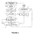
- this piloting principle can be applied to disassembly.
- the control unit 3 of the gearbox can transmit to the control unit 2 of the engine a control command according to which the torque is filtered in consistency with the opening of the lock-up 6 (locking device). It also rains transmit a higher torque setpoint torque driver to manage the re-coupling of the engine so that it does not interfere with disassembly.
- step a the control unit 3 determines if it is necessary to perform a disassembly. In the negative, no particular torque setpoint is transmitted to the engine control unit. If a disassembly is decided, step b is performed.
- step b the process f1 is applied: hydraulic disassembly control is initiated using conventional disassembly strategies. These commands continue independently of the torque instructions transmitted to the control unit 2 of the engine. Once the "hydraulic" disassembly has been started, step c is applied.
Landscapes
- Engineering & Computer Science (AREA)
- Mechanical Engineering (AREA)
- Combustion & Propulsion (AREA)
- Chemical & Material Sciences (AREA)
- General Engineering & Computer Science (AREA)
- Transportation (AREA)
- Automation & Control Theory (AREA)
- Control Of Fluid Gearings (AREA)
- Control Of Transmission Device (AREA)
- Control Of Driving Devices And Active Controlling Of Vehicle (AREA)
- Control Of Vehicle Engines Or Engines For Specific Uses (AREA)
- Arrangement Of Transmissions (AREA)
- Steroid Compounds (AREA)
- Lock And Its Accessories (AREA)
Claims (10)
- Vorrichtung zur Steuerung eines Automatikgetriebes (7), das mit dem Motor (4) eines Kraftfahrzeugs über einen Drehmomentwandler (5) gekoppelt ist, der eine Verriegelungsvorrichtung (6) aufweist, die es ermöglicht, die Abtriebswelle des Motors (4) fest mit der Antriebswelle des Automatikgetriebes (7) zu verbinden, um eine Überbrückung herzustellen und umgekehrt, um eine Überbrückung zu entfernen, wobei die Vorrichtung außerdem eine Steuereinheit (2) des Motors, die geeignet ist, um an den Motor (4) einen Befehl wie eine Drehmomentanforderung zu übertragen, und eine Steuereinheit (3) des Getriebes (7) enthält, die geeignet ist, um an die Steuereinheit (2) des Motors einen Befehl wie einen Drehmomentsollwert zu übertragen, wobei die Drehmomentanforderung von dem vom Fahrer angeforderten Drehmoment und vom Drehmomentsollwert abhängt, dadurch gekennzeichnet, dass bei den Überbrückungen oder beim Entfernen der Überbrückungen die Steuereinheit (3) des Getriebes geeignet ist, um das vom Fahrer angeforderte Drehmoment mit einem Zieldrehmoment zu vergleichen und die Differenz zwischen der Drehzahl des Motors (4) und der Drehzahl der Turbine des Drehmomentwandlers mit einem Schwellwert zu vergleichen, und um an die Steuereinheit (2) des Motors (4) einen Drehmomentsollwert zu übertragen, damit das Motordrehmoment progressiv das Zieldrehmoment erreicht und die Drehzahl des Motors (4) progressiv diejenige der Turbine erreicht.
- Steuervorrichtung nach Anspruch 1, dadurch gekennzeichnet, dass zur Durchführung einer Überbrückung, wenn die Drehzahl der Turbine des Wandlers (5) höher ist als diejenige des Motors (4), die Steuereinheit (3) des Getriebes geeignet ist, um an die Steuereinheit (2) des Motors einen Drehmomentsollwert höher als das vom Fahrer des Fahrzeugs angeforderte Drehmoment zu übertragen, damit die Drehzahl des Motors (4) nahe der Drehzahl der Turbine des Wandlers (5) wird.
- Steuervorrichtung nach Anspruch 1, dadurch gekennzeichnet, dass zur Durchführung einer Überbrückung bei einer schnellen Verringerung des Drehmoments des Motors aufgrund eines Loslassens des Gaspedals (1) durch den Fahrer die Steuereinheit (3) des Getriebes (7) an die Steuereinheit (2) des Motors einen Drehmomentsollwert überträgt, um die Verringerungsgeschwindigkeit des Drehmoments zu verlangsamen.
- Steuervorrichtung nach Anspruch 1, dadurch gekennzeichnet, dass zur Durchführung des Entfernens einer Überbrückung, wenn die Einspritzung des Motors (4) unterbrochen ist, die Steuereinheit (3) des Getriebes geeignet ist, um an die Steuereinheit (2) des Motors einen Drehmomentsollwert zu übertragen, der höher ist als das vom Fahrer des Fahrzeugs angeforderte Drehmoment, damit die Entfernung der Überbrückung nicht erfolgt, wenn die Einspritzung des Motors unterbrochen ist.
- Steuervorrichtung nach Anspruch 1, dadurch gekennzeichnet, dass zur Durchführung des Entfernens einer Überbrückung bei einer schnellen Verringerung des Drehmoments des Motors aufgrund eines Loslassens des Gaspedals durch den Fahrer die Steuereinheit (3) des Getriebes geeignet ist, um an die Steuereinheit (2) des Motors einen Drehmomentsollwert zu übertragen, um die Verringerungsgeschwindigkeit des Drehmoments zu verlangsamen.
- Steuervorrichtung nach einem der Ansprüche 1 bis 5, dadurch gekennzeichnet, dass die Steuereinheit (3) des Getriebes Einrichtungen aufweist, um den an die Verriegelungs- und Entriegelungsvorrichtung (6) bei der Durchführung der Überbrückungen und der Entfernungen der Überbrückungen angewendeten Hydraulikdruck zu regeln.
- Steuervorrichtung nach einem der Ansprüche 1 bis 6, dadurch gekennzeichnet, dass die Steuereinheit (3) des Getriebes (7) geeignet ist, um das Zieldrehmoment und den Drehzahlschwellwert in Abhängigkeit von der Drehzahl der Turbine, der Temperatur des Öls des Getriebes (7) und dem eingelegten Gang zu bestimmen.
- Verfahren zur Steuerung einer Überbrückung oder des Entfernens einer Überbrückung in einem Automatikgetriebe (7), das mit dem Motor (4) eines Kraftfahrzeugs über einen Drehmomentwandler (5) gekoppelt ist, der eine Verriegelungsvorrichtung (6) aufweist, die es ermöglicht, die Abtriebswelle des Motors (4) fest mit der Antriebswelle des Automatikgetriebes (7) zu verbinden, um eine Überbrückung herzustellen und umgekehrt, um eine Überbrückung zu entfernen, und außerdem eine Steuereinheit (2) des Motors, die geeignet ist, um an den Motor (4) einen Befehl wie eine Drehmomentanforderung zu übertragen, und eine Steuereinheit (3) des Getriebes (7) aufweist, die geeignet ist, um an die Steuereinheit (2) des Motors einen Befehl wie einen Drehmomentsollwert zu übertragen, wobei die Drehmomentanforderung von dem vom Fahrer angeforderten Drehmoment und vom Drehmomentsollwert abhängt, dadurch gekennzeichnet, dass, um eine Überbrückung oder das Entfernen einer Überbrückung durchführbar zu machen, die Steuereinheit (3) des Getriebes das vom Fahrer angeforderte Drehmoment mit einem Zieldrehmoment vergleicht und die Differenz zwischen der Drehzahl des Motors (4) und der Drehzahl der Turbine des Drehmomentwandlers mit einem Schwellwert vergleicht und an die Steuereinheit (2) des Motors (4) einen Drehmomentsollwert überträgt, damit das Motordrehmoment progressiv das Zieldrehmoment erreicht und die Drehzahl des Motors (4) progressiv diejenige der Turbine erreicht.
- Verfahren zur Steuerung einer Überbrückung nach Anspruch 8, dadurch gekennzeichnet, dass es die folgenden Schritte enthält:A) die Steuereinheit (3) des Getriebes stellt fest, ob eine Überbrückung durchgeführt werden soll und ob eine Überbrückung bestimmt wurde,b) die Steuereinheit (3) testet, ob das für den Willen des Fahrers (Cc) repräsentative Drehmoment, das von der Steuereinheit (2) des Motors geliefert wird, geringer ist als ein Mindestdrehmoment (Zieldrehmoment Überbrückung), und ob die Drehzahl des Motors geringer als und entfernt von der Drehzahl der Turbine ist (Motordrehzahl (Rm) - Turbinendrehzahl (Rt) < Schwellwert): wenn der Test negativ ist, wird direkt der Schritt C angewendet, ansonsten wird der Schritt I angewendet,C) die Hydrauliksteuerung der Überbrückung wird gestartet,D) die Steuereinheit (3) des Getriebes schickt an die Steuereinheit (2) des Motors einen Drehmomentsollwert (Cons), der progressiv das Fahrerdrehmoment (Cc) erreicht,E) die Steuereinheit (3) des Getriebes testet, ob die gerade durchgeführte Überbrückung beendet ist, und ob der an die Steuereinheit (2) des Motors durch die Steuereinheit (3) des Getriebes übertragene Drehmomentsollwert das Fahrerdrehmoment nahe genug erreicht hat: wenn ja, wird die Überbrückung als beendet angesehen und die Steuereinheit (3) des Getriebes testet, ob eine neue Überbrückung angefordert wird (Rückkehr zum Schritt A): wenn der Test negativ ist, wird Schritt F angewendet,F) die Steuereinheit (3) des Getriebes testet, ob das Fahrerdrehmoment geringer ist als das Zieldrehmoment Überbrückung: wenn nicht, wird der Schritt D weiter durchgeführt: wenn ja, wird Schritt G angewendet,G) die Steuereinheit (3) des Getriebes schickt an die Steuereinheit (2) des Motors einen Drehmomentsollwert, der progressiv das Zieldrehmoment Überbrückung erreicht,H) die Steuereinheit (3) des Getriebes testet, ob das Fahrerdrehmoment höher als das oder gleich dem Zieldrehmoment Überbrückung ist, oder ob die Überbrückung beendet ist: wenn ja, wird Schritt D erneut angewendet, damit der Drehmomentsollwert das Fahrerdrehmoment erreicht: wenn nein, Rückkehr zum Schritt G,I) die Steuereinheit (3) des Getriebes schickt an die Steuereinheit (2) des Motors einen Drehmomentsollwert, der progressiv das Zieldrehmoment Überbrückung erreicht,J) die Steuereinheit (3) des Getriebes testet, ob das Fahrerdrehmoment höher als das oder gleich dem Zieldrehmoment Überbrückung ist, oder ob die Überbrückung beendet ist: wenn ja, wird Schritt D erneut angewendet, damit der Drehmomentsollwert das Fahrerdrehmoment erreicht: wenn nein, wird Schritt K angewendet,K) die Steuereinheit (3) des Getriebes testet, ob die Drehzahl des Motors höher als die oder nahe der Drehzahl der Turbine ist (Motordrehzahl - Turbinendrehzahl ≥ Schwellwert), wenn ja, wird Schritt L angewendet, sonst wird Schritt N angewendet,L) die Hydrauliksteuerung der Überbrückung wird gestartet,M) wenn der Test des Schritts K positiv ist, genügt das laufende Drehmoment, damit die Motordrehzahl höher als die oder gleich der Turbinendrehzahl ist: das Zieldrehmoment Überbrückung wird auf dem realen Drehmoment eingefroren, das vom Motor geliefert wird, und der Drehmomentsollwert erreicht progressiv das Zieldrehmoment Überbrückung,N) die Steuereinheit (3) des Getriebes testet, ob das angewendete Motordrehmoment gleich oder nahe dem Zieldrehmoment ist: wenn der Test negativ ist, Rückkehr zu Schritt I: wenn der Test positiv ist, wird Schritt O angewendet,O) das Zieldrehmoment ist nicht ausreichend, um die Motordrehzahl auf den Pegel der Turbinendrehzahl zurückzubringen, (der Test des Schritts K ist negativ): das Anfangs-Zieldrehmoment wird um ein durch die Steuereinheit (3) des Getriebes festgelegtes Inkrement erhöht, das von mehreren Parametern wie der Differenz zwischen der Motordrehzahl und der Turbinendrehzahl abhängt, dann Rückkehr zum Schritt I.
- Verfahren zur Steuerung des Entfernens einer Überbrückung nach Anspruch 8, dadurch gekennzeichnet, dass es die folgenden Schritte enthält:a) die Steuereinheit (3) stellt fest, ob es notwendig ist, das Entfernen einer Überbrückung durchzuführen: wenn das Entfernen einer Überbrückung bestimmt wird,b) wird die Hydrauliksteuerung des Entfernens der Überbrückung gestartet,c) die Steuereinheit (3) testet, ob das für den Willen des Fahrers (Cc) repräsentative Drehmoment, das von der Steuereinheit (2) des Motors geliefert wird, niedriger ist als ein Mindestdrehmoment, Zieldrehmoment des Entfernens der Überbrückung genannt: wenn der Test negativ ist, wird direkt Schritt f angewendet, sonst wird der nachfolgende Schritt d angewendet,d) die Steuereinheit (3) des Getriebes schickt an die Steuereinheit (2) des Motors einen Drehmomentsollwert, der das Zieldrehmoment des Entfernens der Überbrückung progressiv erreicht,e) die Steuereinheit (3) testet, ob das für den Willen des Fahrers repräsentative Drehmoment höher als das oder gleich dem Zieldrehmoment des Entfernens der Überbrückung ist, oder ob das Entfernen der Überbrückung beendet ist: wenn der Test positiv ist, wird direkt Schritt f angewendet, sonst wird Schritt d angewendet,f) die Steuereinheit (3) des Getriebes sendet an die Steuereinheit (2) des Motors einen Drehmomentsollwert, der progressiv das Fahrerdrehmoment erreicht,g) die Steuereinheit (3) des Getriebes testet, ob das Entfernen der Überbrückung beendet ist und ob der von der Steuereinheit (3) des Getriebes an die Steuereinheit (2) des Motors übertragene Drehmomentsollwert das Fahrerdrehmoment ausreichend nahe erreicht hat: wenn ja, wird das Entfernen der Überbrückung als beendet angesehen und die Steuereinheit (3) des Getriebes testet, ob ein neues Entfernen der Überbrückung angefordert wird (Rückkehr zum Schritt a): wenn der Test negativ ist, wird Schritt e angewendet.
Applications Claiming Priority (2)
| Application Number | Priority Date | Filing Date | Title |
|---|---|---|---|
| FR0405775A FR2870912B1 (fr) | 2004-05-28 | 2004-05-28 | Dispositif et procede de commande d'une boite de vitesses automatisee pour piloter les pontages et depontages |
| PCT/FR2005/050379 WO2005118328A1 (fr) | 2004-05-28 | 2005-05-26 | Dispositif et procede de commande d'une boite de vitesses automatisee pour piloter les pontages et depontages. |
Publications (2)
| Publication Number | Publication Date |
|---|---|
| EP1753984A1 EP1753984A1 (de) | 2007-02-21 |
| EP1753984B1 true EP1753984B1 (de) | 2009-09-30 |
Family
ID=34945934
Family Applications (1)
| Application Number | Title | Priority Date | Filing Date |
|---|---|---|---|
| EP05766702A Expired - Lifetime EP1753984B1 (de) | 2004-05-28 | 2005-05-26 | Vorrichtung und verfahren zur steuerung eines automatikgetriebes zur steuerung von sperrung und entsperrung |
Country Status (7)
| Country | Link |
|---|---|
| US (1) | US7674204B2 (de) |
| EP (1) | EP1753984B1 (de) |
| JP (1) | JP4717066B2 (de) |
| AT (1) | ATE444459T1 (de) |
| DE (1) | DE602005016921D1 (de) |
| FR (1) | FR2870912B1 (de) |
| WO (1) | WO2005118328A1 (de) |
Families Citing this family (9)
| Publication number | Priority date | Publication date | Assignee | Title |
|---|---|---|---|---|
| FR2911656B1 (fr) * | 2007-01-19 | 2009-10-02 | Renault Sas | Procede de pilotage du glissement de l'embrayage de prise directe d'un convertisseur de couple |
| US7899600B2 (en) * | 2007-03-06 | 2011-03-01 | Gm Global Technology Operations, Inc. | Torque converter clutch control system |
| JP4535115B2 (ja) | 2007-10-31 | 2010-09-01 | トヨタ自動車株式会社 | 車両の制御装置 |
| US8448731B2 (en) * | 2007-11-05 | 2013-05-28 | GM Global Technology Operations LLC | Method and apparatus for determination of fast actuating engine torque for a hybrid powertrain system |
| DE102008043109A1 (de) * | 2008-10-23 | 2010-04-29 | Zf Friedrichshafen Ag | Verfahren zum Schließen der Wandlerüberbrückungskupplung in einem Lastschaltgetriebe einer Arbeitsmaschine |
| JP4922317B2 (ja) * | 2009-01-09 | 2012-04-25 | 本田技研工業株式会社 | エンジントルクの制御装置 |
| US8540606B2 (en) * | 2009-11-19 | 2013-09-24 | GM Global Technology Operations LLC | System and method for controlling engine torque |
| EP2501962B1 (de) * | 2009-11-20 | 2019-12-25 | Volvo Construction Equipment AB | Verfahren zur steuerung eines verbrennungsmotors und steuereinheit zur steuerung eines verbrennungsmotors |
| WO2017159203A1 (ja) * | 2016-03-17 | 2017-09-21 | ジヤトコ株式会社 | 自動変速機の制御装置 |
Family Cites Families (13)
| Publication number | Priority date | Publication date | Assignee | Title |
|---|---|---|---|---|
| US649550A (en) * | 1897-03-13 | 1900-05-15 | Charles L Rowland | Art of producing illuminating-gas. |
| JP2927153B2 (ja) * | 1993-09-10 | 1999-07-28 | トヨタ自動車株式会社 | 車両用ロックアップクラッチの制御装置 |
| JP3125570B2 (ja) * | 1994-04-05 | 2001-01-22 | 日産自動車株式会社 | ロックアップ制御装置 |
| JP3031257B2 (ja) * | 1996-08-01 | 2000-04-10 | トヨタ自動車株式会社 | ロックアップクラッチのスリップ制御装置 |
| JP3577966B2 (ja) * | 1998-09-07 | 2004-10-20 | 日産自動車株式会社 | 車両の駆動力制御装置 |
| US6042507A (en) * | 1999-04-22 | 2000-03-28 | Eaton Corporation | Torque converter lockup control |
| DE19949118B4 (de) * | 1999-10-12 | 2008-02-28 | Zf Friedrichshafen Ag | Verfahren zur Motorreduzierung beim Schliessen der Wandlerkupplung für Automatgetriebe eines Kraftfahrzeugs |
| US6468183B1 (en) * | 2000-09-26 | 2002-10-22 | Ford Global Technologies, Inc. | Control for vehicle with transmission |
| US6393350B1 (en) * | 2001-08-10 | 2002-05-21 | Ford Global Technologies, Inc. | Powertrain controller using a feed-forward torque calculation |
| JP2003054291A (ja) * | 2001-08-17 | 2003-02-26 | Toyota Motor Corp | 車両の総合制御装置 |
| DE10242821A1 (de) * | 2002-09-14 | 2004-03-25 | Zf Friedrichshafen Ag | Verfahren zum Schließen einer Wandlerüberbrückungskupplung |
| JP3912254B2 (ja) * | 2002-10-28 | 2007-05-09 | 日産自動車株式会社 | トルクコンバータのスリップ制御装置 |
| US6790159B1 (en) * | 2003-02-21 | 2004-09-14 | Borgwarner, Inc. | Method of controlling a dual clutch transmission |
-
2004
- 2004-05-28 FR FR0405775A patent/FR2870912B1/fr not_active Expired - Fee Related
-
2005
- 2005-05-26 EP EP05766702A patent/EP1753984B1/de not_active Expired - Lifetime
- 2005-05-26 AT AT05766702T patent/ATE444459T1/de not_active IP Right Cessation
- 2005-05-26 JP JP2007514047A patent/JP4717066B2/ja not_active Expired - Fee Related
- 2005-05-26 US US11/596,866 patent/US7674204B2/en not_active Expired - Fee Related
- 2005-05-26 WO PCT/FR2005/050379 patent/WO2005118328A1/fr not_active Ceased
- 2005-05-26 DE DE602005016921T patent/DE602005016921D1/de not_active Expired - Lifetime
Also Published As
| Publication number | Publication date |
|---|---|
| US7674204B2 (en) | 2010-03-09 |
| WO2005118328A1 (fr) | 2005-12-15 |
| US20070207898A1 (en) | 2007-09-06 |
| FR2870912B1 (fr) | 2007-08-10 |
| EP1753984A1 (de) | 2007-02-21 |
| JP2008501088A (ja) | 2008-01-17 |
| ATE444459T1 (de) | 2009-10-15 |
| JP4717066B2 (ja) | 2011-07-06 |
| FR2870912A1 (fr) | 2005-12-02 |
| DE602005016921D1 (de) | 2009-11-12 |
Similar Documents
| Publication | Publication Date | Title |
|---|---|---|
| US10486676B2 (en) | Methods and systems for assisted direct start control | |
| EP2126319B1 (de) | Verfahren zur steuerung des betriebs eines leistungseinheitsgruppe | |
| US8849534B2 (en) | Vehicle control system controlling exertion of braking force on wheel | |
| EP1563207B1 (de) | Auswahlverfahren für die übersetzung eines automatischen getriebes | |
| FR2935660A1 (fr) | Procede et dispositif de compensation de rupture du couple fourni par le groupe motopropulseur d'un vehicule hybride au cours d'un changement de vitesse | |
| WO2005118328A1 (fr) | Dispositif et procede de commande d'une boite de vitesses automatisee pour piloter les pontages et depontages. | |
| FR2764249A1 (fr) | Dispositif pour commander un etat d'enclenchement | |
| US20040176213A1 (en) | Method for controlling a clutch | |
| FR3074534A1 (fr) | Procede de controle d’un moteur de vehicule automobile | |
| RU2536757C2 (ru) | Способ и система управления коробкой передач | |
| US9283961B2 (en) | Method and system for control of a clutch | |
| US10711718B2 (en) | Controller and control method for engines | |
| WO2009101331A1 (fr) | Procede de fonctionnement d'un systeme d'assistance au demarrage d'un vehicule automobile en cote | |
| FR2658564A1 (fr) | Dispositif pour le controle unifie du moteur et de la transmission automatique dans un vehicule automobile. | |
| FR2846606A1 (fr) | Procede de regulation de la vitesse d'un vehicule | |
| EP3292032B1 (de) | Verfahren zur verwaltung präventiver genehmigungsgradienten während der entschleunigung | |
| EP1547849B1 (de) | Steuervorrichtung eines automatisierten Getriebes zur Verbesserung der Hochschaltqualität bei niedrigem Motordrehmoment | |
| EP3221760B1 (de) | Verfahren zur steuerung des drehmoments eines antriebsstrangs mit einer wärmekraftmaschine | |
| JP2005112021A (ja) | 車両の発進制御装置 | |
| EP0819066B1 (de) | Steuersystem für mechanisches getriebe mit einrichtung zur vermeidung von radschlupf | |
| FR3074535B1 (fr) | Procede de controle d’un moteur de vehicule automobile | |
| US20260008464A1 (en) | Method of starting a motor vehicle | |
| FR2880591A1 (fr) | Systeme de controle longitudinal d'une voiture | |
| EP1429011A1 (de) | Verfahren und System zur Steuerung des Drehmoments eines Verbrennungsmotors für ein Automobil | |
| EP1174302B1 (de) | Verfahren zur Steuerung einer Antriebseinheit |
Legal Events
| Date | Code | Title | Description |
|---|---|---|---|
| PUAI | Public reference made under article 153(3) epc to a published international application that has entered the european phase |
Free format text: ORIGINAL CODE: 0009012 |
|
| 17P | Request for examination filed |
Effective date: 20061228 |
|
| AK | Designated contracting states |
Kind code of ref document: A1 Designated state(s): AT BE BG CH CY CZ DE DK EE ES FI FR GB GR HU IE IS IT LI LT LU MC NL PL PT RO SE SI SK TR |
|
| RIN1 | Information on inventor provided before grant (corrected) |
Inventor name: CANIEZ, LAURENT Inventor name: TURPIN, THOMAS |
|
| DAX | Request for extension of the european patent (deleted) | ||
| 17Q | First examination report despatched |
Effective date: 20071108 |
|
| GRAP | Despatch of communication of intention to grant a patent |
Free format text: ORIGINAL CODE: EPIDOSNIGR1 |
|
| GRAS | Grant fee paid |
Free format text: ORIGINAL CODE: EPIDOSNIGR3 |
|
| GRAA | (expected) grant |
Free format text: ORIGINAL CODE: 0009210 |
|
| AK | Designated contracting states |
Kind code of ref document: B1 Designated state(s): AT BE BG CH CY CZ DE DK EE ES FI FR GB GR HU IE IS IT LI LT LU MC NL PL PT RO SE SI SK TR |
|
| REG | Reference to a national code |
Ref country code: CH Ref legal event code: EP Ref country code: GB Ref legal event code: FG4D Free format text: NOT ENGLISH |
|
| REG | Reference to a national code |
Ref country code: IE Ref legal event code: FG4D |
|
| REF | Corresponds to: |
Ref document number: 602005016921 Country of ref document: DE Date of ref document: 20091112 Kind code of ref document: P |
|
| PG25 | Lapsed in a contracting state [announced via postgrant information from national office to epo] |
Ref country code: FI Free format text: LAPSE BECAUSE OF FAILURE TO SUBMIT A TRANSLATION OF THE DESCRIPTION OR TO PAY THE FEE WITHIN THE PRESCRIBED TIME-LIMIT Effective date: 20090930 Ref country code: LT Free format text: LAPSE BECAUSE OF FAILURE TO SUBMIT A TRANSLATION OF THE DESCRIPTION OR TO PAY THE FEE WITHIN THE PRESCRIBED TIME-LIMIT Effective date: 20090930 Ref country code: SE Free format text: LAPSE BECAUSE OF FAILURE TO SUBMIT A TRANSLATION OF THE DESCRIPTION OR TO PAY THE FEE WITHIN THE PRESCRIBED TIME-LIMIT Effective date: 20090930 |
|
| LTIE | Lt: invalidation of european patent or patent extension |
Effective date: 20090930 |
|
| PG25 | Lapsed in a contracting state [announced via postgrant information from national office to epo] |
Ref country code: SI Free format text: LAPSE BECAUSE OF FAILURE TO SUBMIT A TRANSLATION OF THE DESCRIPTION OR TO PAY THE FEE WITHIN THE PRESCRIBED TIME-LIMIT Effective date: 20090930 Ref country code: PL Free format text: LAPSE BECAUSE OF FAILURE TO SUBMIT A TRANSLATION OF THE DESCRIPTION OR TO PAY THE FEE WITHIN THE PRESCRIBED TIME-LIMIT Effective date: 20090930 |
|
| NLV1 | Nl: lapsed or annulled due to failure to fulfill the requirements of art. 29p and 29m of the patents act | ||
| PG25 | Lapsed in a contracting state [announced via postgrant information from national office to epo] |
Ref country code: PT Free format text: LAPSE BECAUSE OF FAILURE TO SUBMIT A TRANSLATION OF THE DESCRIPTION OR TO PAY THE FEE WITHIN THE PRESCRIBED TIME-LIMIT Effective date: 20100201 Ref country code: ES Free format text: LAPSE BECAUSE OF FAILURE TO SUBMIT A TRANSLATION OF THE DESCRIPTION OR TO PAY THE FEE WITHIN THE PRESCRIBED TIME-LIMIT Effective date: 20100110 Ref country code: IS Free format text: LAPSE BECAUSE OF FAILURE TO SUBMIT A TRANSLATION OF THE DESCRIPTION OR TO PAY THE FEE WITHIN THE PRESCRIBED TIME-LIMIT Effective date: 20100130 Ref country code: EE Free format text: LAPSE BECAUSE OF FAILURE TO SUBMIT A TRANSLATION OF THE DESCRIPTION OR TO PAY THE FEE WITHIN THE PRESCRIBED TIME-LIMIT Effective date: 20090930 Ref country code: RO Free format text: LAPSE BECAUSE OF FAILURE TO SUBMIT A TRANSLATION OF THE DESCRIPTION OR TO PAY THE FEE WITHIN THE PRESCRIBED TIME-LIMIT Effective date: 20090930 Ref country code: CZ Free format text: LAPSE BECAUSE OF FAILURE TO SUBMIT A TRANSLATION OF THE DESCRIPTION OR TO PAY THE FEE WITHIN THE PRESCRIBED TIME-LIMIT Effective date: 20090930 |
|
| REG | Reference to a national code |
Ref country code: IE Ref legal event code: FD4D |
|
| PG25 | Lapsed in a contracting state [announced via postgrant information from national office to epo] |
Ref country code: SK Free format text: LAPSE BECAUSE OF FAILURE TO SUBMIT A TRANSLATION OF THE DESCRIPTION OR TO PAY THE FEE WITHIN THE PRESCRIBED TIME-LIMIT Effective date: 20090930 Ref country code: CY Free format text: LAPSE BECAUSE OF FAILURE TO SUBMIT A TRANSLATION OF THE DESCRIPTION OR TO PAY THE FEE WITHIN THE PRESCRIBED TIME-LIMIT Effective date: 20090930 |
|
| PG25 | Lapsed in a contracting state [announced via postgrant information from national office to epo] |
Ref country code: AT Free format text: LAPSE BECAUSE OF FAILURE TO SUBMIT A TRANSLATION OF THE DESCRIPTION OR TO PAY THE FEE WITHIN THE PRESCRIBED TIME-LIMIT Effective date: 20090930 |
|
| PG25 | Lapsed in a contracting state [announced via postgrant information from national office to epo] |
Ref country code: DK Free format text: LAPSE BECAUSE OF FAILURE TO SUBMIT A TRANSLATION OF THE DESCRIPTION OR TO PAY THE FEE WITHIN THE PRESCRIBED TIME-LIMIT Effective date: 20090930 Ref country code: IE Free format text: LAPSE BECAUSE OF FAILURE TO SUBMIT A TRANSLATION OF THE DESCRIPTION OR TO PAY THE FEE WITHIN THE PRESCRIBED TIME-LIMIT Effective date: 20090930 Ref country code: NL Free format text: LAPSE BECAUSE OF FAILURE TO SUBMIT A TRANSLATION OF THE DESCRIPTION OR TO PAY THE FEE WITHIN THE PRESCRIBED TIME-LIMIT Effective date: 20090930 |
|
| PLBE | No opposition filed within time limit |
Free format text: ORIGINAL CODE: 0009261 |
|
| STAA | Information on the status of an ep patent application or granted ep patent |
Free format text: STATUS: NO OPPOSITION FILED WITHIN TIME LIMIT |
|
| 26N | No opposition filed |
Effective date: 20100701 |
|
| PG25 | Lapsed in a contracting state [announced via postgrant information from national office to epo] |
Ref country code: GR Free format text: LAPSE BECAUSE OF FAILURE TO SUBMIT A TRANSLATION OF THE DESCRIPTION OR TO PAY THE FEE WITHIN THE PRESCRIBED TIME-LIMIT Effective date: 20091231 |
|
| BERE | Be: lapsed |
Owner name: RENAULT S.A.S. Effective date: 20100531 |
|
| PG25 | Lapsed in a contracting state [announced via postgrant information from national office to epo] |
Ref country code: MC Free format text: LAPSE BECAUSE OF NON-PAYMENT OF DUE FEES Effective date: 20100531 |
|
| REG | Reference to a national code |
Ref country code: CH Ref legal event code: PL |
|
| PG25 | Lapsed in a contracting state [announced via postgrant information from national office to epo] |
Ref country code: LI Free format text: LAPSE BECAUSE OF NON-PAYMENT OF DUE FEES Effective date: 20100531 Ref country code: CH Free format text: LAPSE BECAUSE OF NON-PAYMENT OF DUE FEES Effective date: 20100531 |
|
| PG25 | Lapsed in a contracting state [announced via postgrant information from national office to epo] |
Ref country code: IT Free format text: LAPSE BECAUSE OF FAILURE TO SUBMIT A TRANSLATION OF THE DESCRIPTION OR TO PAY THE FEE WITHIN THE PRESCRIBED TIME-LIMIT Effective date: 20090930 Ref country code: BE Free format text: LAPSE BECAUSE OF NON-PAYMENT OF DUE FEES Effective date: 20100531 |
|
| PG25 | Lapsed in a contracting state [announced via postgrant information from national office to epo] |
Ref country code: LU Free format text: LAPSE BECAUSE OF NON-PAYMENT OF DUE FEES Effective date: 20100526 Ref country code: HU Free format text: LAPSE BECAUSE OF FAILURE TO SUBMIT A TRANSLATION OF THE DESCRIPTION OR TO PAY THE FEE WITHIN THE PRESCRIBED TIME-LIMIT Effective date: 20100401 Ref country code: BG Free format text: LAPSE BECAUSE OF FAILURE TO SUBMIT A TRANSLATION OF THE DESCRIPTION OR TO PAY THE FEE WITHIN THE PRESCRIBED TIME-LIMIT Effective date: 20090930 |
|
| PG25 | Lapsed in a contracting state [announced via postgrant information from national office to epo] |
Ref country code: TR Free format text: LAPSE BECAUSE OF FAILURE TO SUBMIT A TRANSLATION OF THE DESCRIPTION OR TO PAY THE FEE WITHIN THE PRESCRIBED TIME-LIMIT Effective date: 20090930 |
|
| REG | Reference to a national code |
Ref country code: FR Ref legal event code: PLFP Year of fee payment: 11 |
|
| REG | Reference to a national code |
Ref country code: FR Ref legal event code: PLFP Year of fee payment: 12 |
|
| PGFP | Annual fee paid to national office [announced via postgrant information from national office to epo] |
Ref country code: DE Payment date: 20160520 Year of fee payment: 12 Ref country code: GB Payment date: 20160520 Year of fee payment: 12 |
|
| PGFP | Annual fee paid to national office [announced via postgrant information from national office to epo] |
Ref country code: FR Payment date: 20160520 Year of fee payment: 12 |
|
| REG | Reference to a national code |
Ref country code: DE Ref legal event code: R119 Ref document number: 602005016921 Country of ref document: DE |
|
| GBPC | Gb: european patent ceased through non-payment of renewal fee |
Effective date: 20170526 |
|
| REG | Reference to a national code |
Ref country code: FR Ref legal event code: ST Effective date: 20180131 |
|
| PG25 | Lapsed in a contracting state [announced via postgrant information from national office to epo] |
Ref country code: DE Free format text: LAPSE BECAUSE OF NON-PAYMENT OF DUE FEES Effective date: 20171201 Ref country code: GB Free format text: LAPSE BECAUSE OF NON-PAYMENT OF DUE FEES Effective date: 20170526 |
|
| PG25 | Lapsed in a contracting state [announced via postgrant information from national office to epo] |
Ref country code: FR Free format text: LAPSE BECAUSE OF NON-PAYMENT OF DUE FEES Effective date: 20170531 |