EP1754540A2 - Düse für einen Druckbehälter - Google Patents
Düse für einen Druckbehälter Download PDFInfo
- Publication number
- EP1754540A2 EP1754540A2 EP06119021A EP06119021A EP1754540A2 EP 1754540 A2 EP1754540 A2 EP 1754540A2 EP 06119021 A EP06119021 A EP 06119021A EP 06119021 A EP06119021 A EP 06119021A EP 1754540 A2 EP1754540 A2 EP 1754540A2
- Authority
- EP
- European Patent Office
- Prior art keywords
- aerosol
- cap
- channel
- nozzle according
- swirl chamber
- Prior art date
- Legal status (The legal status is an assumption and is not a legal conclusion. Google has not performed a legal analysis and makes no representation as to the accuracy of the status listed.)
- Withdrawn
Links
- 239000000443 aerosol Substances 0.000 title claims abstract description 53
- 238000003466 welding Methods 0.000 claims abstract description 5
- 238000005553 drilling Methods 0.000 claims abstract description 3
- 239000004743 Polypropylene Substances 0.000 claims description 2
- -1 polypropylene Polymers 0.000 claims description 2
- 229920001155 polypropylene Polymers 0.000 claims description 2
- 238000005507 spraying Methods 0.000 abstract description 6
- 238000004519 manufacturing process Methods 0.000 abstract description 4
- 230000015572 biosynthetic process Effects 0.000 abstract 1
- 239000012530 fluid Substances 0.000 description 7
- 239000007921 spray Substances 0.000 description 6
- 230000006835 compression Effects 0.000 description 3
- 238000007906 compression Methods 0.000 description 3
- 239000000463 material Substances 0.000 description 3
- 230000002093 peripheral effect Effects 0.000 description 3
- 238000003825 pressing Methods 0.000 description 3
- 238000010276 construction Methods 0.000 description 2
- 230000000994 depressogenic effect Effects 0.000 description 1
- 238000001746 injection moulding Methods 0.000 description 1
- 239000007788 liquid Substances 0.000 description 1
- 238000000034 method Methods 0.000 description 1
- 239000003595 mist Substances 0.000 description 1
- 239000003973 paint Substances 0.000 description 1
- 239000004033 plastic Substances 0.000 description 1
- 229920003023 plastic Polymers 0.000 description 1
- 238000007789 sealing Methods 0.000 description 1
- 238000000926 separation method Methods 0.000 description 1
Images


Classifications
-
- B—PERFORMING OPERATIONS; TRANSPORTING
- B65—CONVEYING; PACKING; STORING; HANDLING THIN OR FILAMENTARY MATERIAL
- B65D—CONTAINERS FOR STORAGE OR TRANSPORT OF ARTICLES OR MATERIALS, e.g. BAGS, BARRELS, BOTTLES, BOXES, CANS, CARTONS, CRATES, DRUMS, JARS, TANKS, HOPPERS, FORWARDING CONTAINERS; ACCESSORIES, CLOSURES, OR FITTINGS THEREFOR; PACKAGING ELEMENTS; PACKAGES
- B65D83/00—Containers or packages with special means for dispensing contents
- B65D83/14—Containers for dispensing liquid or semi-liquid contents by internal gaseous pressure, i.e. aerosol containers comprising propellant
- B65D83/16—Actuating means
- B65D83/20—Actuator caps
Definitions
- the present invention relates to an aerosol nozzle comprising a first part provided with a pressure face and a second part to be connected to an aerosol container, wherein said second part and first part are to be fastened to one another and delimit a channel at the interface thereof, the second part being provided with an inlet opening, the outlet opening of the nozzle being provided exclusively in one of said parts, and a swirl chamber being present.
- the gas dissolved in the liquid is released.
- the gas should preferably be released in the form of bubbles having substantially the same predetermined diameter. This allows an optimum spray pattern to be obtained.
- EP 0 883 557 A1 discloses an aerosol nozzle wherein the channel for the fluid to be sprayed is delimited in both the first and second parts.
- the first and second parts are provided with cooperating sealing means, such as a peripheral edge and a peripheral groove, which provide a seal when the first and second parts are positioned one inside the other. This seal is temporary, thus allowing the user to clean the flow channel after simple separation of the first and second parts.
- the flow channel merges with the outlet or outflow opening, which is also delimited in both parts.
- Aerosols have a large number of uses.
- One of the many uses is the spraying of paint and the like. In this case, precise spraying is important for the result to be achieved by the user.
- EP 0 883 557 has been found to be unsuitable in such cases because the spray issuing from the outlet opening is non-uniform.
- the chosen production method has also been found to limit possibilities for complex configuration of the outlet opening.
- US 3,652,018 describes a nozzle wherein connected to a channel is a swirl chamber, the outlet of which is, in turn, connected to an annular channel connected to the outflow nozzle.
- the object of the present invention is to provide a construction allowing improved spraying of the fluid to be sprayed.
- the channel extending between the outlet opening of the aerosol container and the outlet of the aerosol nozzle is still delimited between a first part and a second part which cooperate with one another in order thus to define a channel therebetween.
- this division does not extend to the outlet opening of the aerosol nozzle.
- This outlet opening which determines the shape of the spray, is formed exclusively in either the first part or the second part and is preferably formed in the first part. This provides a high degree of design freedom for the configuration of said outlet opening.
- the shape of the outlet opening may be ensured.
- the swirl chamber is also delimited by both the first and second parts.
- a further swirl chamber is provided downstream of the above-described swirl chamber.
- This further swirl chamber is preferably provided directly before the outflow nozzle.
- the channel extends, in the part wherein the outlet opening is not formed, over a limited length in the downstream direction. At the downstream end thereof, the delimitation between the relevant part and the other part is completely sealed.
- one or more swirl chambers are attached in the channel. These swirl chambers may also be formed in both the first and the second part.
- the first and second parts are permanently connected to one another.
- a permanent connection of this type may be produced by appropriate choice of the plastics material from which the first and second parts are made, by ultrasonic welding.
- Polypropylene is a material with which a weld connection of this type may easily be produced.
- a recess is provided in both the first part and the second part, and these recesses jointly delimit the channel.
- This channel is preferably substantially circular in cross section, so a first half circular cylinder is formed in the first part and a second half circular cylinder is formed in the second part.
- the invention also relates to an aerosol cap which may be positioned on the end of an aerosol container in order thus to form an aerosol.
- the nozzle according to the present invention is received in this aerosol cap, so the first part is part of the aerosol cap.
- the first part is connected to said aerosol cap in a hinged manner, for example by a film hinge.
- there are further connections between the first part and the aerosol cap that have to be broken during/before the first use. It may thus at least be checked whether the aerosol has previously been used and, secondly, this provides additional protection against unintentional pressing of the first part.
- reference numeral 1 denotes an aerosol consisting of a container part 1 with an outlet (not shown in greater detail) consisting of a tube which extends vertically in the illustrated position and is connected to a valve. Pressing the tube opens the valve and allows the content of the aerosol to escape.
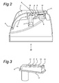
- a cap 3 is attached to the aerosol container 2. The details of the cap 3 are apparent from Fig. 2.
- the cap 3 consists of a part which is stationary with respect to the aerosol 2 and an aerosol nozzle 16 connected thereto in a hinged manner via a hinge 5.
- the aerosol nozzle 16 consists of a first part 4 which is connected in its entirety to the cap 2 via the film hinge 5 by injection-moulding.
- a separate second part 6 is provided.
- the above-described vertical tube of the aerosol container (not shown) is received during the use in the inlet opening 7 of the second part.
- the second part By exerting pressure on the pressure face 15 of the first part, the second part is also moved downward and the valve is thus activated.
- the fluid is then able to issue through the channel 8 and swirl chambers 9, 10 via the outflow opening 11.
- the channel 8, like the swirl chambers 9 and 10, is also formed in both the first part 4 and the second part 6.
- the channel part, attached in the first part, is denoted in Fig. 5 by reference numeral 12 and in Fig. 3 the channel part of the second part is denoted by reference numeral 13.
- Fig. 3 also shows that the second part is provided with a peripheral edge 17.
- the second part may be positioned in the first part by gentle pressing, after which a connection between the edge 17 and the first part is produced by means of ultrasonic welding. The presence of an edge allows the weld spot to be located precisely at the desired position.
- the outlet opening 11 is formed exclusively in one of the first or second parts, in the present example in the first part.
- the channel part, attached in the second part ends before the outlet opening 11 and at this location the second part, and more particularly the channel part 13 thereof, is sealed all-round from the first part.
- the outflow opening may be produced, for example, by laser drilling.
- An outlet opening of this type may be round but may also have another shape conceivable in the prior art.
- connection between the first and second parts is preferably permanent.
- Fig. 2 shows that the first part 4 is connected to the cap 2 via the hinge 5.
- connection bridges 14 Fig. 4 which are broken and when the aerosol is first used, i.e. when the first part is depressed for the first time on the pressure face 15. These bridges also serve to guide the first part with respect to the cap.
- the outlet 11 allows the outlet 11 to be configured in any desired manner. This applies not only to the shape of the opening but also to the position thereof. It is thus possible to apply the longitudinal centre line of the opening at any desired angle.
- the fact that the opening is formed exclusively in one of the parts provides complete design freedom of this type.
- the comparatively simple moulds are sufficient for the production of the channel through which the fluid moves.
Landscapes
- Chemical & Material Sciences (AREA)
- Dispersion Chemistry (AREA)
- Engineering & Computer Science (AREA)
- Mechanical Engineering (AREA)
- Containers And Packaging Bodies Having A Special Means To Remove Contents (AREA)
Applications Claiming Priority (1)
| Application Number | Priority Date | Filing Date | Title |
|---|---|---|---|
| NL1029746A NL1029746C2 (nl) | 2005-08-16 | 2005-08-16 | Spuitbusmondstuk. |
Publications (1)
| Publication Number | Publication Date |
|---|---|
| EP1754540A2 true EP1754540A2 (de) | 2007-02-21 |
Family
ID=36087739
Family Applications (1)
| Application Number | Title | Priority Date | Filing Date |
|---|---|---|---|
| EP06119021A Withdrawn EP1754540A2 (de) | 2005-08-16 | 2006-08-16 | Düse für einen Druckbehälter |
Country Status (2)
| Country | Link |
|---|---|
| EP (1) | EP1754540A2 (de) |
| NL (1) | NL1029746C2 (de) |
Cited By (2)
| Publication number | Priority date | Publication date | Assignee | Title |
|---|---|---|---|---|
| GB2475422A (en) * | 2009-11-17 | 2011-05-18 | Univ Salford | Spray Discharge Assembly with Fluid Jets Directed Against Sharp Edge |
| JP2015009837A (ja) * | 2013-06-28 | 2015-01-19 | 株式会社吉野工業所 | エアゾール容器用ノズル |
Citations (3)
| Publication number | Priority date | Publication date | Assignee | Title |
|---|---|---|---|---|
| US3652018A (en) | 1970-06-12 | 1972-03-28 | Precision Valve Corp | Plug and cavity mechanical break-up button |
| EP0883557A1 (de) | 1996-02-28 | 1998-12-16 | Incro Limited | Sprühvorrichtungen und düsen |
| US20020060255A1 (en) | 2000-11-15 | 2002-05-23 | Jean-Francois Benoist | Dispensing head and assembly including the same |
Family Cites Families (4)
| Publication number | Priority date | Publication date | Assignee | Title |
|---|---|---|---|---|
| US3178120A (en) * | 1962-08-08 | 1965-04-13 | Henry C Kappel | Two piece spray nozzle |
| FR2141455B1 (de) * | 1971-06-03 | 1974-02-15 | Wassilieff Victor | |
| US4074861A (en) * | 1976-06-18 | 1978-02-21 | Realex Corporation | Spray pattern control structure and method |
| FR2853635B1 (fr) * | 2003-04-09 | 2007-04-06 | Rexam Dispensing Sys | Bouton-poussoir de pulverisateur |
-
2005
- 2005-08-16 NL NL1029746A patent/NL1029746C2/nl not_active IP Right Cessation
-
2006
- 2006-08-16 EP EP06119021A patent/EP1754540A2/de not_active Withdrawn
Patent Citations (3)
| Publication number | Priority date | Publication date | Assignee | Title |
|---|---|---|---|---|
| US3652018A (en) | 1970-06-12 | 1972-03-28 | Precision Valve Corp | Plug and cavity mechanical break-up button |
| EP0883557A1 (de) | 1996-02-28 | 1998-12-16 | Incro Limited | Sprühvorrichtungen und düsen |
| US20020060255A1 (en) | 2000-11-15 | 2002-05-23 | Jean-Francois Benoist | Dispensing head and assembly including the same |
Cited By (4)
| Publication number | Priority date | Publication date | Assignee | Title |
|---|---|---|---|---|
| GB2475422A (en) * | 2009-11-17 | 2011-05-18 | Univ Salford | Spray Discharge Assembly with Fluid Jets Directed Against Sharp Edge |
| GB2475422B (en) * | 2009-11-17 | 2012-02-29 | Univ Salford | Spray discharge assembly |
| US9296549B2 (en) | 2009-11-17 | 2016-03-29 | The Salford Valve Company Limited | Spray discharge assembly |
| JP2015009837A (ja) * | 2013-06-28 | 2015-01-19 | 株式会社吉野工業所 | エアゾール容器用ノズル |
Also Published As
| Publication number | Publication date |
|---|---|
| NL1029746C2 (nl) | 2007-02-19 |
Similar Documents
| Publication | Publication Date | Title |
|---|---|---|
| US8079534B2 (en) | Spray nozzle | |
| EP2296820B1 (de) | Abgabeverschluss für eine fächersprühdüse | |
| US4193519A (en) | Liquid dispensing closure having capillary bores | |
| CN109071096B (zh) | 盖帽组件 | |
| US9511381B2 (en) | Spray nozzle and aerosol product | |
| CN101873894B (zh) | 流体分配喷嘴 | |
| AU2019404213A1 (en) | Container, closure, and methods for manufacture | |
| EP2729257B1 (de) | Ausgabegehäuse für lüfteröffnung | |
| US5110011A (en) | Non-releasable spray head and dip tube assembly | |
| EP3765203B1 (de) | Sprühkappe für einen sprühbehälter | |
| US7510102B2 (en) | Clog resistant actuator and overcap | |
| CN1833997B (zh) | 用于分配装置的自密封喷嘴 | |
| EP1340548B1 (de) | Düseneinsatz für einen handbetätigten Flüssigkeitszerstäuber | |
| US9604773B2 (en) | Insert with nozzle formed by micro stepped and conical surfaces | |
| EP1754540A2 (de) | Düse für einen Druckbehälter | |
| EP3766587A1 (de) | Öffnung und sprühbehälter damit | |
| US20050252665A1 (en) | Closure, which reacts to heat, for sprinklers and nozzles | |
| US20230278050A1 (en) | Fluid reservoir having an optionally insertable inner bag | |
| US20220396412A1 (en) | Cartridge and method for producing a cartridge | |
| US20230002089A1 (en) | Method for producing a cartridge and cartridge | |
| JPH075148B2 (ja) | 噴射用アクチュエータ | |
| KR102735070B1 (ko) | 에어로졸 | |
| CN208684449U (zh) | 废水排放装置以及可与龙头分离的龙头基座 | |
| JP4827092B2 (ja) | 微量液体流出容器 | |
| EP2070598B1 (de) | Druckknopf, dessen Verteilerkammer zwischen einem Körper und einer aufgesetzten Abdeckung gebildet wird |
Legal Events
| Date | Code | Title | Description |
|---|---|---|---|
| PUAI | Public reference made under article 153(3) epc to a published international application that has entered the european phase |
Free format text: ORIGINAL CODE: 0009012 |
|
| AK | Designated contracting states |
Kind code of ref document: A2 Designated state(s): AT BE BG CH CY CZ DE DK EE ES FI FR GB GR HU IE IS IT LI LT LU LV MC NL PL PT RO SE SI SK TR |
|
| AX | Request for extension of the european patent |
Extension state: AL BA HR MK YU |
|
| STAA | Information on the status of an ep patent application or granted ep patent |
Free format text: STATUS: THE APPLICATION IS DEEMED TO BE WITHDRAWN |
|
| 18D | Application deemed to be withdrawn |
Effective date: 20100401 |