EP1754629A2 - Dispositif de retenue de chargement pour un véhicule automobile - Google Patents
Dispositif de retenue de chargement pour un véhicule automobile Download PDFInfo
- Publication number
- EP1754629A2 EP1754629A2 EP06016413A EP06016413A EP1754629A2 EP 1754629 A2 EP1754629 A2 EP 1754629A2 EP 06016413 A EP06016413 A EP 06016413A EP 06016413 A EP06016413 A EP 06016413A EP 1754629 A2 EP1754629 A2 EP 1754629A2
- Authority
- EP
- European Patent Office
- Prior art keywords
- anchoring
- lug
- base body
- connection unit
- anchoring lug
- Prior art date
- Legal status (The legal status is an assumption and is not a legal conclusion. Google has not performed a legal analysis and makes no representation as to the accuracy of the status listed.)
- Granted
Links
- 238000004873 anchoring Methods 0.000 claims abstract description 84
- 238000002347 injection Methods 0.000 claims description 3
- 239000007924 injection Substances 0.000 claims description 3
- 238000004519 manufacturing process Methods 0.000 description 5
- 238000003780 insertion Methods 0.000 description 2
- 230000037431 insertion Effects 0.000 description 2
- 230000009286 beneficial effect Effects 0.000 description 1
- 238000009434 installation Methods 0.000 description 1
- 239000000463 material Substances 0.000 description 1
Images



Classifications
-
- B—PERFORMING OPERATIONS; TRANSPORTING
- B60—VEHICLES IN GENERAL
- B60P—VEHICLES ADAPTED FOR LOAD TRANSPORTATION OR TO TRANSPORT, TO CARRY, OR TO COMPRISE SPECIAL LOADS OR OBJECTS
- B60P7/00—Securing or covering of load on vehicles
- B60P7/06—Securing of load
- B60P7/08—Securing to the vehicle floor or sides
- B60P7/0807—Attachment points
Definitions
- the invention relates to a device for anchoring loads, belts or the like in motor vehicles, in particular in a trunk of a motor vehicle, with a frame-like base body to which an anchoring lug is pivotally mounted via a connecting unit.
- connection unit comprises as connection parts, on the one hand, an insertion part with joint openings, furthermore a pivot pin, which is mounted in the joint openings of the insert, so that the anchoring lug is pivotable about a horizontal axis, and a third connection part, which is located between the joint openings of the insert part is stored to determine the anchorage lug in a predetermined adjustment position.
- the anchoring lug is pivotally mounted about a horizontal pivot axis to the frame-like base body.
- U1 From the DE 20 2004 020 091 U1 is to reduce the assembly cost, a device for anchoring of cargoes and the like provided in motor vehicles, which consists only of a single component.
- the component has V-shaped anchoring legs to allow differently oriented engagement of straps, buckles or the like.
- the known anchoring device since the known anchoring device has no pivotable anchoring eyelet, the variability of the anchoring device is limited.
- Object of the present invention is therefore to develop a device for anchoring of cargoes or the like in motor vehicles with a pivotable Anank ceremoniessinate such that the manufacturing and assembly costs is further reduced.
- connection unit is integrally formed.
- the particular advantage of the invention is that can be significantly reduced by a one-piece design of a connection unit of the manufacturing and assembly costs.
- the anchoring eyelet is partially encompassed in a storage location area by the one side of the main body and partially surrounded by the connecting unit from the opposite side, so that a secure and rattle-free mounting of the anchoring eyelet is ensured.
- the device according to the invention comprises only three components, the assembly of the same is substantially simplified.
- the device according to the invention can be delivered pre-assembled to the motor vehicle manufacturer, so that this only has to make a fixation of the anchoring device on a body part of the motor vehicle, for example by means of screwing.
- the anchoring eyelet is clamped and pivoted to the base body from an underside of the base body by means of the connection unit.
- the connection unit has on the one hand bearing means for the anchoring lug and on the other hand connecting means for a preferably releasable fastening of the connection unit to the base body. In this way it is ensured that in the mounting position of the device, a reliable pivoting of the anchoring eyelet is ensured about an axis of rotation.
- an axle element is arranged integrated, preferably at least two storage locations each between a bearing shell the main body and a bearing shell of the connection unit is mounted.
- connection unit is designed as a connecting plate, which has locking means for latching connection with the frame-like base body. After insertion of the anchorage lug in the body and subsequent clipping of the connecting plate to the body, the axle of the anchoring eyelet is fixed in the mounting position.
- connection plate has latching means, such that the anchoring lug is fixed in a latching manner in predetermined different adjustment positions (latching positions).
- the bearing shell of the connection unit is designed such that the anchoring lug is pivotable only by applying a predetermined adjusting force.
- the connecting plate is designed biased such that in the mounting position an axial and / or radial force (holding force) is exerted on the axle of the anchoring eye, which applies to overcome during pivoting.
- the axle of the anchoring loop is therefore not stored with clearance between bearing means of the body and the connection unit, but it is always necessary for pivoting the anchoring eyelet a relatively small adjustment, so that the user always feels a resistance during pivoting of the anchoring eyelet, which favors a smooth pivoting ,
- a detent force required to move or apply the anchoring eye into or out of a detent position is comparatively much higher.
- a stop is assigned to the axle element of the anchoring eyelet so that the anchoring eyelet can only be adjusted to a limited pivoting angle.
- this can be provided in a simple manner over-rotation protection, without additional components are required.
- the anchoring lug and the base body are designed as a Zinktikg tellteil and the connection unit as an injection molded part.
- these three components of the anchoring device are designed such that they can be produced by means of tools without slide / side slide. In this way, the production cost can be further reduced.
- a device according to the invention for anchoring loads, belts or the like in motor vehicles finds particular use in a trunk of a motor vehicle.
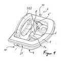
- the device according to the invention consists essentially of a frame-like basic body 1, an anchoring lug 3, which is pivotable about a horizontal axis 2 and mounted in a depression of the frame-shaped basic body 1, and a connecting unit 4.
- the connecting unit 4 is integrally formed as a connecting plate, on the one hand via latching means for attaching the connecting unit 4 to the base body 1 and for bringing the Anank ceremoniessinate 3 in at least one latching position on the one hand and on the other bearing means for supporting the Anank réellesinate 3 on the other.
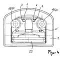
- the connecting plate 4 has as a latching means two spaced apart from each other at the front end of a base side 5 of the connecting plate 4 projecting first locking pin 6, which engage in corresponding openings 7 of the main body 1 detent.
- the connecting plate 4 as a locking means in a central region of the base side 5 projecting second locking pin 6 ', which secured in an assembly position in which the anchoring lug 3 axially and radially is arranged on the base body 1, at a front edge 8 of a recess 9 of the body 1 is applied by clamping.
- the connecting plate 4 captive and at least free of play in the direction of extension of the connecting plate 4 perpendicular to the horizontal pivot axis 2 attached to the base body 1, wherein the anchoring lug 3 is only rotatably supported about the horizontal pivot axis 2.
- the bearing means of the connecting plate 4 are formed at opposite bearing locations 10 each as a bearing shell 11 for receiving in each case one end-side portion 12 of an integrally connected to the anchoring lug 3 axle member 13 thereof.
- the axis of symmetry of the axle element 13 coincides with the horizontal pivot axis 2.
- the bearing shells 11 are each formed semicircular and have such a distance to each other, which is slightly smaller than the distance of the end portions 12 of the axle 13 to each other, so that the axle member 13 of the anchoring lug 3 in the axial and / or radial direction by clamping (under a Contact pressure) is stored.
- the connecting plate 4 has in a central region a resilient latching lug 14 which protrudes from the base side 5 in the same direction as the locking pins 6, 6 '.
- the Latch 14 is perpendicular to the horizontal pivot axis 2 resiliently formed so that it engages with a horizontal axis 2 facing the free end portion in an upright locking position of the anchoring lug 3 in a recess formed as a recess 15 of the anchoring lug 3.
- the latching receptacle 15 is arranged in the region of the axle element 13.
- the anchoring lug 3 In the upright locking position, the anchoring lug 3 is fixed relative to the base body 1 and the connecting plate 4, so that a simplified attachment of straps, buckles, items and the like is made possible on the anchoring lug 3.
- a latching force is required which is substantially greater than the adjusting force which always acts upon the pivoting of the anchoring lug 3.
- the anchoring lug 3 is guided from an underside 16 of the main body 1 forth through the recess 9 until a front end of the axle member 13 final collar 17 comes to a bearing shell 18 of the body 1 to the plant.
- the bearing shell 18 is arranged in the region of the storage location 10.
- the connecting plate 4 is clipped from below to an underside of the Grundköpers 1 by engaging the locking pins 6, 6 ', wherein the bearing shells 11 of the connecting plate 4, the end-side portion 12 of the axle element 13 - as described above - comprise clamping and thus the anchoring lug 3 backlash and is fixed by clamping to the base body 1.
- the components of the anchoring device are now in the mounting position.
- the anchoring device thus formed can now, for example, a motor vehicle manufacturer be provided in a pre-assembled, so that in a further step only by a screw the anchoring device to a body part, for example in the trunk of a motor vehicle, can be attached.
- the base body 1 and the connecting plate 4 each have two mutually aligned bores 19 and 20, can engage through the screws, not shown, for fastening the anchoring device (assembly) to the body part.
- On an opposite side of the locking pin 6 of the base side 5 of the connecting plate 4 is followed by an angled upright Wandungsabexcellent 24, by means of which the connecting plate 4 is supported in the mounting position on a narrow-side inner edge 25 of the base body 1.
- the collar 17 of the axle element 13 has a stop 21 which abuts against the bearing shell 18 of the base body 1 in the upright detent position of the anchoring lug 3 and thus prevents further rotation.
- the shaft member 13 may also have a plurality of locking receptacles 15 which are arranged distributed in the circumferential direction of the shaft member 13, so that the anchoring lug 3 can assume a plurality of locking positions.
- the pivoting range of the anchoring lug 3 is limited to 90 ° between the recessed detent position and the upright detent position.
- the detent lug 14 engages latchingly on a latching edge 22 of the axle element 13.
- the anchoring lug 3 and the connecting plate 4 may also be free of locking receptacles 15, locking edges 22 and a detent 14, so that only relatively low adjustment forces are required when pivoting the anchoring lug 3 about the pivot axis 2.
- the main body 1 and the anchoring lug 3 are each made of a Zinkdruckg cordteil.
- the connection plate 4 is made of a plastic material as an injection molded part.
- the cast parts 1, 3, 4 are each formed so that no tools with slides, in particular with side sliders, are required for the production thereof. As a result, the production cost can be further reduced in addition to the preference of the small number of components.
- the anchoring lug 3 has, in addition to the axle 13, a bracket 23 which is connected in one piece with the axle element 13 at the end. Characterized in that the anchoring lug 3 is mounted pivotably through 90 °, the forces in the event of a collision of the motor vehicle in an optimal direction of the bracket 23 of the anchoring lug 3 can be added.
- the main body 1 can take over the Anank ceremoniessinate 3, the forces occurring in the event of a collision and secure the load.
Landscapes
- Engineering & Computer Science (AREA)
- Transportation (AREA)
- Mechanical Engineering (AREA)
- Superstructure Of Vehicle (AREA)
- Connection Of Plates (AREA)
- Motor Or Generator Frames (AREA)
- Vehicle Body Suspensions (AREA)
- Forklifts And Lifting Vehicles (AREA)
- Lighting Device Outwards From Vehicle And Optical Signal (AREA)
- Coloring Foods And Improving Nutritive Qualities (AREA)
- Lock And Its Accessories (AREA)
Priority Applications (1)
| Application Number | Priority Date | Filing Date | Title |
|---|---|---|---|
| PL06016413T PL1754629T3 (pl) | 2005-08-15 | 2006-08-07 | Urządzenie do mocowania ładunków na pojeździe |
Applications Claiming Priority (1)
| Application Number | Priority Date | Filing Date | Title |
|---|---|---|---|
| DE202005012945U DE202005012945U1 (de) | 2005-08-15 | 2005-08-15 | Vorrichtung zum Verankern von Ladegütern im Kraftfahrzeug |
Publications (3)
| Publication Number | Publication Date |
|---|---|
| EP1754629A2 true EP1754629A2 (fr) | 2007-02-21 |
| EP1754629A3 EP1754629A3 (fr) | 2007-12-26 |
| EP1754629B1 EP1754629B1 (fr) | 2009-04-08 |
Family
ID=35267929
Family Applications (1)
| Application Number | Title | Priority Date | Filing Date |
|---|---|---|---|
| EP06016413A Active EP1754629B1 (fr) | 2005-08-15 | 2006-08-07 | Dispositif de retenue de chargement pour un véhicule automobile |
Country Status (4)
| Country | Link |
|---|---|
| EP (1) | EP1754629B1 (fr) |
| AT (1) | ATE427859T1 (fr) |
| DE (2) | DE202005012945U1 (fr) |
| PL (1) | PL1754629T3 (fr) |
Cited By (1)
| Publication number | Priority date | Publication date | Assignee | Title |
|---|---|---|---|---|
| DE102018213827A1 (de) * | 2018-08-16 | 2020-02-20 | Rud Ketten Rieger & Dietz Gmbh U. Co. Kg | Anschlagvorrichtung mit Schnappmechanismus |
Families Citing this family (4)
| Publication number | Priority date | Publication date | Assignee | Title |
|---|---|---|---|---|
| DE102006002783A1 (de) * | 2006-01-20 | 2007-07-26 | Bayerische Motoren Werke Ag | Vorrichtung zur Halterung von Ladegut |
| EP2289736B1 (fr) * | 2009-08-31 | 2012-03-28 | YMOS GmbH | Dispositif de fixation |
| DE102009040524A1 (de) * | 2009-09-08 | 2011-03-10 | Rud Ketten Rieger & Dietz Gmbh & Co. Kg | Vorrichtung zum Anschlagen, Heben und/oder Zurren von Gütern, mit einem Ringbock und einer Axialsicherung, und Verfahren zu deren Herstellung |
| DE102012006556A1 (de) * | 2012-04-02 | 2013-10-02 | Huf Hülsbeck & Fürst Gmbh & Co. Kg | Halter |
Citations (2)
| Publication number | Priority date | Publication date | Assignee | Title |
|---|---|---|---|---|
| DE202004003237U1 (de) | 2004-02-27 | 2004-05-06 | Ymos-Hdo Gmbh | Vorrichtung zum Verzurren von Gepäckteilen im Kraftfahrzeug |
| DE202004020091U1 (de) | 2004-12-29 | 2005-02-24 | Eduard Ubrig + Söhne GmbH | Verankerungsvorrichtung |
Family Cites Families (5)
| Publication number | Priority date | Publication date | Assignee | Title |
|---|---|---|---|---|
| DE10005717A1 (de) * | 2000-02-09 | 2001-08-16 | Volkswagen Ag | Verzurreinrichtung, insbesondere für einen Kraftfahrzeug-Laderaum |
| DE20204413U1 (de) * | 2002-03-19 | 2002-09-05 | Lohmann Apparatebau GmbH, 34266 Niestetal | Klappgriff |
| DE10324649B4 (de) * | 2003-05-30 | 2007-05-24 | Airbus Deutschland Gmbh | Zurrpunktvorrichtung für ein Frachtladesystem eines Transportmittels, insbesondere eines Flugzeuges |
| DE102004002050A1 (de) * | 2004-01-15 | 2005-08-04 | Volkswagen Ag | Anordnung zur Befestigung von Gegenständen an einer Wand |
| DE102005026964A1 (de) * | 2005-06-10 | 2006-12-14 | Trade World One Gmbh | Gurtöse |
-
2005
- 2005-08-15 DE DE202005012945U patent/DE202005012945U1/de not_active Expired - Lifetime
-
2006
- 2006-08-07 DE DE502006003365T patent/DE502006003365D1/de active Active
- 2006-08-07 PL PL06016413T patent/PL1754629T3/pl unknown
- 2006-08-07 EP EP06016413A patent/EP1754629B1/fr active Active
- 2006-08-07 AT AT06016413T patent/ATE427859T1/de not_active IP Right Cessation
Patent Citations (2)
| Publication number | Priority date | Publication date | Assignee | Title |
|---|---|---|---|---|
| DE202004003237U1 (de) | 2004-02-27 | 2004-05-06 | Ymos-Hdo Gmbh | Vorrichtung zum Verzurren von Gepäckteilen im Kraftfahrzeug |
| DE202004020091U1 (de) | 2004-12-29 | 2005-02-24 | Eduard Ubrig + Söhne GmbH | Verankerungsvorrichtung |
Cited By (4)
| Publication number | Priority date | Publication date | Assignee | Title |
|---|---|---|---|---|
| DE102018213827A1 (de) * | 2018-08-16 | 2020-02-20 | Rud Ketten Rieger & Dietz Gmbh U. Co. Kg | Anschlagvorrichtung mit Schnappmechanismus |
| CN112839895A (zh) * | 2018-08-16 | 2021-05-25 | 路德-李格和蒂茨链条有限公司 | 带卡扣机构的锚固装置 |
| CN112839895B (zh) * | 2018-08-16 | 2024-05-17 | 路德-李格和蒂茨链条有限公司 | 带卡扣机构的锚固装置 |
| US12031571B2 (en) | 2018-08-16 | 2024-07-09 | Rud Ketten Rieger & Dietz Gmbh U. Co. Kg | Anchor device with snap mechanism |
Also Published As
| Publication number | Publication date |
|---|---|
| DE202005012945U1 (de) | 2005-10-27 |
| EP1754629B1 (fr) | 2009-04-08 |
| PL1754629T3 (pl) | 2009-09-30 |
| DE502006003365D1 (de) | 2009-05-20 |
| ATE427859T1 (de) | 2009-04-15 |
| EP1754629A3 (fr) | 2007-12-26 |
Similar Documents
| Publication | Publication Date | Title |
|---|---|---|
| DE102012010230B4 (de) | Montagevorrichtung zur Befestigung eines Gurtschlosses | |
| EP3286042B1 (fr) | Ensemble volant, module de coussin gonflable et un corps du volant | |
| DE60318624T2 (de) | Lastträgerfuss | |
| EP2156084A1 (fr) | Système de fixation | |
| DE60302538T2 (de) | Selbstverriegelnde Verbindung zwischen einer Stange mit Kugelkopf und einem flachen Abschnitt | |
| WO2015036263A1 (fr) | Unité de verrouillage pour siège de véhicule, et siège de véhicule | |
| EP1754629B1 (fr) | Dispositif de retenue de chargement pour un véhicule automobile | |
| DE102007058331B4 (de) | Fahrzeugsitz | |
| DE102005050222B4 (de) | Gelenkbeschlag für ein Rückenlehnengelenk eines Kraftfahrzeugsitzes | |
| DE102015110594A1 (de) | Armauflage für ein Fahrzeuginnenausstattungsteil | |
| DE60114493T2 (de) | Haltevorrichtung für eine Bowdenzughülle | |
| EP1814758B1 (fr) | Serrure, en particulier pour un vehicule automobile | |
| DE3630446C2 (de) | Möbelscharnier | |
| DE4142598C1 (en) | Glove pocket lid hinge - has fastener plate allocated to body-fixed tap with straps allowing plate to move in two dimensions relative to support | |
| DE102009058815B4 (de) | Haltevorrichtung für Anbauteile von Fahrzeugen | |
| DE4039692C2 (de) | Halterung für einen Kraftfahrzeugsitz | |
| DE29716096U1 (de) | Schnellverschluß | |
| DE8816665U1 (de) | Höhenverstellvorrichtung für einen Beschlag eines Sicherheitsgurt-Rückhaltesystems in Kraftfahrzeugen | |
| DE10228046B4 (de) | Halterungsöse für ein Verzurrmittel zum Sichern von Ladegut in einem Fahrzeug | |
| DE102013219409B4 (de) | Verriegelungseinheit für einen fahrzeugsitz und fahrzeugsitz | |
| DE202007009721U1 (de) | An einem Bauteil formschlüssig festgelegte Halteeinrichtung | |
| DE102009017407B4 (de) | Haltevorrichtung für Getränkebehälter | |
| DE10137645B4 (de) | Armlehne, insbesondere für Fahrzeuge | |
| DE3801759C2 (fr) | ||
| EP1803187A1 (fr) | Dispositif de fixation d'une antenne |
Legal Events
| Date | Code | Title | Description |
|---|---|---|---|
| PUAI | Public reference made under article 153(3) epc to a published international application that has entered the european phase |
Free format text: ORIGINAL CODE: 0009012 |
|
| AK | Designated contracting states |
Kind code of ref document: A2 Designated state(s): AT BE BG CH CY CZ DE DK EE ES FI FR GB GR HU IE IS IT LI LT LU LV MC NL PL PT RO SE SI SK TR |
|
| AX | Request for extension of the european patent |
Extension state: AL BA HR MK YU |
|
| PUAL | Search report despatched |
Free format text: ORIGINAL CODE: 0009013 |
|
| AK | Designated contracting states |
Kind code of ref document: A3 Designated state(s): AT BE BG CH CY CZ DE DK EE ES FI FR GB GR HU IE IS IT LI LT LU LV MC NL PL PT RO SE SI SK TR |
|
| AX | Request for extension of the european patent |
Extension state: AL BA HR MK YU |
|
| 17P | Request for examination filed |
Effective date: 20080331 |
|
| 17Q | First examination report despatched |
Effective date: 20080604 |
|
| AKX | Designation fees paid |
Designated state(s): AT BE BG CH CY CZ DE DK EE ES FI FR GB GR HU IE IS IT LI LT LU LV MC NL PL PT RO SE SI SK TR |
|
| AXX | Extension fees paid |
Extension state: RS Payment date: 20080331 Extension state: MK Payment date: 20080331 Extension state: AL Payment date: 20080331 Extension state: BA Payment date: 20080331 Extension state: HR Payment date: 20080331 |
|
| GRAP | Despatch of communication of intention to grant a patent |
Free format text: ORIGINAL CODE: EPIDOSNIGR1 |
|
| GRAS | Grant fee paid |
Free format text: ORIGINAL CODE: EPIDOSNIGR3 |
|
| GRAA | (expected) grant |
Free format text: ORIGINAL CODE: 0009210 |
|
| AK | Designated contracting states |
Kind code of ref document: B1 Designated state(s): AT BE BG CH CY CZ DE DK EE ES FI FR GB GR HU IE IS IT LI LT LU LV MC NL PL PT RO SE SI SK TR |
|
| AX | Request for extension of the european patent |
Extension state: AL BA HR MK RS |
|
| REG | Reference to a national code |
Ref country code: GB Ref legal event code: FG4D Free format text: NOT ENGLISH |
|
| REG | Reference to a national code |
Ref country code: CH Ref legal event code: EP |
|
| REG | Reference to a national code |
Ref country code: IE Ref legal event code: FG4D |
|
| REF | Corresponds to: |
Ref document number: 502006003365 Country of ref document: DE Date of ref document: 20090520 Kind code of ref document: P |
|
| PG25 | Lapsed in a contracting state [announced via postgrant information from national office to epo] |
Ref country code: SI Free format text: LAPSE BECAUSE OF FAILURE TO SUBMIT A TRANSLATION OF THE DESCRIPTION OR TO PAY THE FEE WITHIN THE PRESCRIBED TIME-LIMIT Effective date: 20090408 |
|
| REG | Reference to a national code |
Ref country code: SE Ref legal event code: TRGR |
|
| NLV1 | Nl: lapsed or annulled due to failure to fulfill the requirements of art. 29p and 29m of the patents act | ||
| REG | Reference to a national code |
Ref country code: PL Ref legal event code: T3 |
|
| REG | Reference to a national code |
Ref country code: IE Ref legal event code: FD4D |
|
| PG25 | Lapsed in a contracting state [announced via postgrant information from national office to epo] |
Ref country code: ES Free format text: LAPSE BECAUSE OF FAILURE TO SUBMIT A TRANSLATION OF THE DESCRIPTION OR TO PAY THE FEE WITHIN THE PRESCRIBED TIME-LIMIT Effective date: 20090719 Ref country code: FI Free format text: LAPSE BECAUSE OF FAILURE TO SUBMIT A TRANSLATION OF THE DESCRIPTION OR TO PAY THE FEE WITHIN THE PRESCRIBED TIME-LIMIT Effective date: 20090408 Ref country code: LT Free format text: LAPSE BECAUSE OF FAILURE TO SUBMIT A TRANSLATION OF THE DESCRIPTION OR TO PAY THE FEE WITHIN THE PRESCRIBED TIME-LIMIT Effective date: 20090408 Ref country code: PT Free format text: LAPSE BECAUSE OF FAILURE TO SUBMIT A TRANSLATION OF THE DESCRIPTION OR TO PAY THE FEE WITHIN THE PRESCRIBED TIME-LIMIT Effective date: 20090908 |
|
| PG25 | Lapsed in a contracting state [announced via postgrant information from national office to epo] |
Ref country code: NL Free format text: LAPSE BECAUSE OF FAILURE TO SUBMIT A TRANSLATION OF THE DESCRIPTION OR TO PAY THE FEE WITHIN THE PRESCRIBED TIME-LIMIT Effective date: 20090408 Ref country code: LV Free format text: LAPSE BECAUSE OF FAILURE TO SUBMIT A TRANSLATION OF THE DESCRIPTION OR TO PAY THE FEE WITHIN THE PRESCRIBED TIME-LIMIT Effective date: 20090408 Ref country code: IS Free format text: LAPSE BECAUSE OF FAILURE TO SUBMIT A TRANSLATION OF THE DESCRIPTION OR TO PAY THE FEE WITHIN THE PRESCRIBED TIME-LIMIT Effective date: 20090808 |
|
| PG25 | Lapsed in a contracting state [announced via postgrant information from national office to epo] |
Ref country code: RO Free format text: LAPSE BECAUSE OF FAILURE TO SUBMIT A TRANSLATION OF THE DESCRIPTION OR TO PAY THE FEE WITHIN THE PRESCRIBED TIME-LIMIT Effective date: 20090408 Ref country code: EE Free format text: LAPSE BECAUSE OF FAILURE TO SUBMIT A TRANSLATION OF THE DESCRIPTION OR TO PAY THE FEE WITHIN THE PRESCRIBED TIME-LIMIT Effective date: 20090408 Ref country code: IE Free format text: LAPSE BECAUSE OF FAILURE TO SUBMIT A TRANSLATION OF THE DESCRIPTION OR TO PAY THE FEE WITHIN THE PRESCRIBED TIME-LIMIT Effective date: 20090408 Ref country code: DK Free format text: LAPSE BECAUSE OF FAILURE TO SUBMIT A TRANSLATION OF THE DESCRIPTION OR TO PAY THE FEE WITHIN THE PRESCRIBED TIME-LIMIT Effective date: 20090408 |
|
| PLBE | No opposition filed within time limit |
Free format text: ORIGINAL CODE: 0009261 |
|
| STAA | Information on the status of an ep patent application or granted ep patent |
Free format text: STATUS: NO OPPOSITION FILED WITHIN TIME LIMIT |
|
| BERE | Be: lapsed |
Owner name: YMOS G.M.B.H. Effective date: 20090831 |
|
| 26N | No opposition filed |
Effective date: 20100111 |
|
| PG25 | Lapsed in a contracting state [announced via postgrant information from national office to epo] |
Ref country code: BG Free format text: LAPSE BECAUSE OF FAILURE TO SUBMIT A TRANSLATION OF THE DESCRIPTION OR TO PAY THE FEE WITHIN THE PRESCRIBED TIME-LIMIT Effective date: 20090708 Ref country code: MC Free format text: LAPSE BECAUSE OF NON-PAYMENT OF DUE FEES Effective date: 20090831 |
|
| PG25 | Lapsed in a contracting state [announced via postgrant information from national office to epo] |
Ref country code: BE Free format text: LAPSE BECAUSE OF NON-PAYMENT OF DUE FEES Effective date: 20090831 |
|
| PG25 | Lapsed in a contracting state [announced via postgrant information from national office to epo] |
Ref country code: GR Free format text: LAPSE BECAUSE OF FAILURE TO SUBMIT A TRANSLATION OF THE DESCRIPTION OR TO PAY THE FEE WITHIN THE PRESCRIBED TIME-LIMIT Effective date: 20090709 |
|
| PG25 | Lapsed in a contracting state [announced via postgrant information from national office to epo] |
Ref country code: AT Free format text: LAPSE BECAUSE OF NON-PAYMENT OF DUE FEES Effective date: 20090807 |
|
| PGFP | Annual fee paid to national office [announced via postgrant information from national office to epo] |
Ref country code: CZ Payment date: 20100727 Year of fee payment: 5 Ref country code: DE Payment date: 20100830 Year of fee payment: 5 Ref country code: FR Payment date: 20100901 Year of fee payment: 5 Ref country code: IT Payment date: 20100827 Year of fee payment: 5 Ref country code: SE Payment date: 20100823 Year of fee payment: 5 Ref country code: SK Payment date: 20100802 Year of fee payment: 5 |
|
| PGFP | Annual fee paid to national office [announced via postgrant information from national office to epo] |
Ref country code: GB Payment date: 20100823 Year of fee payment: 5 Ref country code: PL Payment date: 20100727 Year of fee payment: 5 |
|
| REG | Reference to a national code |
Ref country code: CH Ref legal event code: PL |
|
| PG25 | Lapsed in a contracting state [announced via postgrant information from national office to epo] |
Ref country code: CH Free format text: LAPSE BECAUSE OF NON-PAYMENT OF DUE FEES Effective date: 20100831 Ref country code: LU Free format text: LAPSE BECAUSE OF NON-PAYMENT OF DUE FEES Effective date: 20090807 Ref country code: LI Free format text: LAPSE BECAUSE OF NON-PAYMENT OF DUE FEES Effective date: 20100831 |
|
| PG25 | Lapsed in a contracting state [announced via postgrant information from national office to epo] |
Ref country code: HU Free format text: LAPSE BECAUSE OF FAILURE TO SUBMIT A TRANSLATION OF THE DESCRIPTION OR TO PAY THE FEE WITHIN THE PRESCRIBED TIME-LIMIT Effective date: 20091009 |
|
| PG25 | Lapsed in a contracting state [announced via postgrant information from national office to epo] |
Ref country code: TR Free format text: LAPSE BECAUSE OF FAILURE TO SUBMIT A TRANSLATION OF THE DESCRIPTION OR TO PAY THE FEE WITHIN THE PRESCRIBED TIME-LIMIT Effective date: 20090408 |
|
| PG25 | Lapsed in a contracting state [announced via postgrant information from national office to epo] |
Ref country code: CY Free format text: LAPSE BECAUSE OF FAILURE TO SUBMIT A TRANSLATION OF THE DESCRIPTION OR TO PAY THE FEE WITHIN THE PRESCRIBED TIME-LIMIT Effective date: 20090408 |
|
| REG | Reference to a national code |
Ref country code: SE Ref legal event code: EUG |
|
| GBPC | Gb: european patent ceased through non-payment of renewal fee |
Effective date: 20110807 |
|
| PG25 | Lapsed in a contracting state [announced via postgrant information from national office to epo] |
Ref country code: CZ Free format text: LAPSE BECAUSE OF NON-PAYMENT OF DUE FEES Effective date: 20110807 Ref country code: SK Free format text: LAPSE BECAUSE OF NON-PAYMENT OF DUE FEES Effective date: 20110807 |
|
| REG | Reference to a national code |
Ref country code: SK Ref legal event code: MM4A Ref document number: E 5622 Country of ref document: SK Effective date: 20110807 |
|
| REG | Reference to a national code |
Ref country code: FR Ref legal event code: ST Effective date: 20120430 |
|
| PG25 | Lapsed in a contracting state [announced via postgrant information from national office to epo] |
Ref country code: IT Free format text: LAPSE BECAUSE OF NON-PAYMENT OF DUE FEES Effective date: 20110807 |
|
| REG | Reference to a national code |
Ref country code: DE Ref legal event code: R119 Ref document number: 502006003365 Country of ref document: DE Effective date: 20120301 |
|
| PG25 | Lapsed in a contracting state [announced via postgrant information from national office to epo] |
Ref country code: FR Free format text: LAPSE BECAUSE OF NON-PAYMENT OF DUE FEES Effective date: 20110831 Ref country code: GB Free format text: LAPSE BECAUSE OF NON-PAYMENT OF DUE FEES Effective date: 20110807 |
|
| PG25 | Lapsed in a contracting state [announced via postgrant information from national office to epo] |
Ref country code: PL Free format text: LAPSE BECAUSE OF NON-PAYMENT OF DUE FEES Effective date: 20110807 |
|
| REG | Reference to a national code |
Ref country code: PL Ref legal event code: LAPE |
|
| PG25 | Lapsed in a contracting state [announced via postgrant information from national office to epo] |
Ref country code: SE Free format text: LAPSE BECAUSE OF NON-PAYMENT OF DUE FEES Effective date: 20110808 |
|
| PG25 | Lapsed in a contracting state [announced via postgrant information from national office to epo] |
Ref country code: DE Free format text: LAPSE BECAUSE OF NON-PAYMENT OF DUE FEES Effective date: 20120301 |