EP1754632B1 - Haltevorrichtung, vorzugsweise zur Befestigung eines Bauteils an einer Fahrzeugkarosse - Google Patents
Haltevorrichtung, vorzugsweise zur Befestigung eines Bauteils an einer Fahrzeugkarosse Download PDFInfo
- Publication number
- EP1754632B1 EP1754632B1 EP06013778A EP06013778A EP1754632B1 EP 1754632 B1 EP1754632 B1 EP 1754632B1 EP 06013778 A EP06013778 A EP 06013778A EP 06013778 A EP06013778 A EP 06013778A EP 1754632 B1 EP1754632 B1 EP 1754632B1
- Authority
- EP
- European Patent Office
- Prior art keywords
- section
- retaining
- retaining device
- positioning
- vehicle body
- Prior art date
- Legal status (The legal status is an assumption and is not a legal conclusion. Google has not performed a legal analysis and makes no representation as to the accuracy of the status listed.)
- Not-in-force
Links
- 239000000463 material Substances 0.000 claims abstract description 10
- 238000001746 injection moulding Methods 0.000 claims abstract description 4
- 238000009434 installation Methods 0.000 claims description 2
- 230000002349 favourable effect Effects 0.000 description 6
- 238000004519 manufacturing process Methods 0.000 description 4
- 238000005553 drilling Methods 0.000 description 3
- 239000000853 adhesive Substances 0.000 description 2
- 230000001070 adhesive effect Effects 0.000 description 2
- 239000002390 adhesive tape Substances 0.000 description 2
- 238000000034 method Methods 0.000 description 2
- 238000000926 separation method Methods 0.000 description 2
- XLYOFNOQVPJJNP-UHFFFAOYSA-N water Substances O XLYOFNOQVPJJNP-UHFFFAOYSA-N 0.000 description 2
- 230000009286 beneficial effect Effects 0.000 description 1
- 230000000694 effects Effects 0.000 description 1
- 239000002184 metal Substances 0.000 description 1
- 239000003973 paint Substances 0.000 description 1
- 238000007789 sealing Methods 0.000 description 1
- 230000003313 weakening effect Effects 0.000 description 1
- 238000003466 welding Methods 0.000 description 1
Images

Classifications
-
- B—PERFORMING OPERATIONS; TRANSPORTING
- B60—VEHICLES IN GENERAL
- B60R—VEHICLES, VEHICLE FITTINGS, OR VEHICLE PARTS, NOT OTHERWISE PROVIDED FOR
- B60R13/00—Elements for body-finishing, identifying, or decorating; Arrangements or adaptations for advertising purposes
- B60R13/04—External Ornamental or guard strips; Ornamental inscriptive devices thereon
-
- B—PERFORMING OPERATIONS; TRANSPORTING
- B60—VEHICLES IN GENERAL
- B60R—VEHICLES, VEHICLE FITTINGS, OR VEHICLE PARTS, NOT OTHERWISE PROVIDED FOR
- B60R13/00—Elements for body-finishing, identifying, or decorating; Arrangements or adaptations for advertising purposes
- B60R13/02—Internal Trim mouldings ; Internal Ledges; Wall liners for passenger compartments; Roof liners
- B60R13/0206—Arrangements of fasteners and clips specially adapted for attaching inner vehicle liners or mouldings
Definitions
- the invention relates to a holding device, which is preferably provided for fastening a component to a vehicle body having at least one holding portion for fixing the component, and having at least one positioning portion, at least at a point of a surface of the vehicle body for positioning the holding device on the vehicle body at least in sections can be brought into contact.
- a holding device which is preferably provided for fastening a component to a vehicle body having at least one holding portion for fixing the component, and having at least one positioning portion, at least at a point of a surface of the vehicle body for positioning the holding device on the vehicle body at least in sections can be brought into contact.
- document US 2002/0101096 A1 discloses such a holding device.
- holding devices such as retaining strips, for fixing components such as cover or water strips on a vehicle body with this connected so that they riveted, clipped and glued or glued in less applications only.
- the retaining strips here are made of either metal or plastic.
- Decisive in the fixation of the aforementioned toolbars is the unique positioning of the strips on the vehicle body.
- the positioning of cover or water catch strips with respect to the upper edge of the A-pillar of a vehicle body is called.
- the clear positioning of this bar on the A-pillar prevents a gap between the A-pillar and the cover or water-catching bar and thus results in a sealing connection.
- the positioning of the toolbars is done through holes drilled in the A-pillar. These holes, through which the rivets or clips are inserted, provide a defined position of the toolbar along the A-pillar.
- riveted designs are a high production cost for drilling the holes in the A-pillar and riveting the retaining strip. Even with clipped and glued versions of a high production cost for drilling the holes in the A-pillar is required, and also in this embodiment, a considerable Kon Stammionsaufwand member side is required.
- the positioning of a retaining strip can also be done by the use of templates that are placed on the vehicle and removed after positioning. This procedure must be repeated on the opposite side of the vehicle. The assembly engineer must pick up the template, place it on the vehicle, position the retaining strip, then remove and place the template again. These assembly operations require a great deal of production time, and moreover, in the spare parts business, each repair shop must be equipped with such a positioning template.
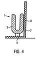
- the plant side of the retaining strip is on the posting of the A-pillar sheet and thereby ensures a clear positioning of the retaining strip (see Figure 4).
- a disadvantage of this design is the need for a defined design of the A-pillar such that the contact side of the retaining strip must be perpendicular to the shutdown of the A-pillar plate.
- the known positioning aid is not applicable to exclusively glued retaining strips.
- this embodiment of the retaining strips has the disadvantage that positioning of the retaining strip in the spare part case difficult or impossible, since it sits directly next to the windshield. If it comes to the assembly of the windshield to the leakage of adhesive - the space for mounting the retaining strip for receiving emerging adhesive is used deliberately in the windshield assembly - so a clear positioning of the retaining strip is prevented. This has the consequence that the windshield has to be removed.
- the object of the invention is therefore to improve a holding device of the type mentioned, so that on the one hand a simple positioning of the holding device on a vehicle body while independence from the design of the vehicle body is possible.
- a holding device of the type mentioned in which the holding device has at least one positioning, which is after solving the positioning and assembly of the holding device of this.
- the holding device according to the invention requires no additional templates that are placed on the vehicle body before the assembly process. This saves the vehicle manufacturer from having to pay for additional operations such as picking up, placing on and taking off the template.
- Positionierabites can either be reused or recycled, resulting in huge economic benefits while saving a lot of resources.
- the holding device according to the invention allows a very simple and accurate installation in the replacement part case.
- the holding device consists of polymeric material. As a result, the holding device can be manufactured very cost-effectively with low weight at the same time.
- the holding device can also be advantageous for the holding device to be produced in an injection molding process. This results in a cost effective and fast production.
- the holding device is strip-shaped. This achieves a very accurate and fast attachment even with greater longitudinal extent of the holding device, whereby the assembly cost is significantly reduced. In addition, reduced by this design, the number of mounting components to be mounted.
- the at least one holding section surrounds the assembled component at least in sections. This results in a permanent and secure connection.
- the at least one holding section has a substantially U-shaped cross section. This creates a particularly stable and secure connection between the holding section and the component.
- the leg of the holding section facing the vehicle body in the assembled state can be arranged at least in sections parallel to the surface of the vehicle body. This manages a good investment of the holding section on the vehicle body, which is durable and stable.
- the holding section is connected at least partially cohesively to the surface of the vehicle body. This ensures a permanent and firm connection between the holding section and the vehicle body.
- the holding device has two or more holding sections. This results in a particularly stable and reliable connection between holding section and component.
- the holding device is strip-shaped and has three or more holding sections, wherein each two adjacent holding sections have the same distance from each other.
- this results in a very accurate and fast attachment even with greater longitudinal extent of the holding device, on the other hand, this results in a particularly stable and secure connection between holding section and component with uniform mechanical stress.
- the at least one positioning portion is integrally connected to the holding portion, wherein it consists of the same material. This results in a very simple, stable and cost-effective connection between positioning and holding section.
- the at least one positioning section is detachably connected to the holding section once. This results in a particularly simple and quick way to separate the positioning of the holding section.
- the at least one positioning portion is connected to the leg of the holding portion, which faces the vehicle body in the assembled state. This results in a better investment of the holding and positioning on the vehicle body and thus a more accurate positioning, on the other hand there is a force application point, which is cheaper with respect to the mechanical load of the holding portion during the separation of the positioning.
- the at least one positioning section is connected to the holding section in such a way that the connection point is designed as a predetermined breaking point. This makes it possible to realize a quick and easy separation of the positioning section of the holding section at a defined location.
- the predetermined breaking point is further spaced from the curved portion of the holding portion, as the end of the leg, which faces away from the vehicle body in the assembled state of the holding portion. This arrangement of the predetermined breaking point ensures that the positioning section can be deflected so far that it comes to a break at the predetermined breaking point.
- the predetermined breaking point is adjacent to the region of the holding portion, which is materially connected to the surface of the vehicle body. This results in only a small mechanical load in the region of the cohesive connection during detachment of the positioning section from the holding section.
- the at least one positioning section preferably has a positioning stop. This positioning stop allows easy, quick and accurate positioning of the positioning section on the vehicle body.
- the positioning stop may have a projecting web which can be brought into abutment, at least in sections, on a surface of the vehicle body.
- This form of positioning stopper makes it possible to set up the positioning section on the vehicle body very easily and quickly.
- the projecting web is arranged substantially perpendicular to the part of the positioning portion which is connected to the holding portion. This results in a particularly secure and accurate system and thus positioning of the positioning of the vehicle body.
- the at least one positioning section has a force application lever for releasing the positioning section from the mounted holding section. This allows a very simple and quick release of the positioning of the mounted holding section without the use of additional tools and thus without the risk of damaging the vehicle body.
- the force application lever is formed from the extension of the part of the positioning section, which is connected to the holding section. This results in a particularly simple geometric arrangement of the force application lever, which also has a favorable effect on the introduction of force for separating the positioning section from the holding section.
- the holding device has two or more positioning sections. As a result, it is particularly well ensured that the positioning section can be brought into contact quickly and at the same time precisely with the vehicle body.
- the invention also relates to a component which is arranged with a holding device according to one of the preceding claims on a vehicle body.
- the invention relates to a vehicle with a holding device according to one of the preceding claims.
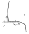
- Fig. 1 shows in cross section the holding device in contact with the vehicle body.
- the holding device 1 is made of polymeric material. It is designed strip-shaped and was produced by injection molding. In the illustrated embodiment, the holding device 1 has a substantially U-shaped holding portion 3 and a substantially T-shaped positioning portion 4. Of course, the holding device may have more holding and positioning portions, wherein both the holding portion and the positioning portion may be shaped differently , Holding section 3 and positioning section 4 are integrally connected to each other and made of the same material.
- the connection point is designed as a predetermined breaking point 5.
- the leg of the substantially U-shaped holding section 3, which faces the vehicle body 2 when the holding section 3 is mounted, is arranged essentially parallel to the surface of the vehicle body 2.
- an adhesive tape 8 is arranged, which connects the holding portion 3 with the vehicle body 2 cohesively.
- the positioning adjoins 4 On the leg of the substantially U-shaped holding portion 3, which faces the vehicle body 2 in the assembled state, the positioning adjoins 4, wherein the connecting portion has a deliberately produced material weakening, the predetermined breaking point 5 when separating the positioning portion 4 from the holding portion. 3 serves.
- the predetermined breaking point 5 is further spaced from the curved portion of the holding portion 3 as the end of the leg, which faces away from the vehicle body 2 in the assembled state of the holding portion 3.
- the predetermined breaking point 5 is arranged adjacent to the region of the holding portion 3, which is materially connected to the surface of the vehicle body 2.
- the part of the positioning section 4, which adjoins the predetermined breaking point 5, results from the extension of the leg of the vehicle body 2 facing the holding section 3. From this extension branches off a web in a substantially vertical direction, which serves as a positioning stop 6.
- the holding device 1 is used for fastening components to a vehicle body 2.
- the positioning of a holding device on the vehicle body takes place in exclusively glued holding devices with the aid of positioning aids mounted on the holding device, which are supported on a parking of the vehicle body (see FIG. 4).
- this known from the prior art positioning aid is bound to defined designs of the vehicle body such that the plant side of the holding device must be perpendicular to the shutdown of the vehicle body to ensure a clear positioning of the holding device.
- the holding section 3 is not based on a shutdown of the vehicle body 2, but is first placed on the positioning stop 6 with a surface of the vehicle body 2 into abutment. The positioning stop 6 rests against the surface of the vehicle body 2 at least in sections.
- This application results in an exact positioning of the holding section 3 on the vehicle body 2.
- the removal of the liner, which covers the adhesive tape 8 takes place downward and the holding section 3 of the holding device 1 pressed against the vehicle body 2, whereby an at least partially cohesive connection between the holding portion 3 and the vehicle body 2 results.
- the application of a force to the force application lever 7 takes place in the direction away from the vehicle body 2.
- the positioning section 4 is lifted off the painted vehicle body 2, whereby damage to the paint is avoided.
- the positioning section 4 moves further in the direction away from the vehicle body 2, until it comes to break in the region of the predetermined breaking point 5, whereby the positioning section 4 can be detached from the holding section 3.
Landscapes
- Engineering & Computer Science (AREA)
- Mechanical Engineering (AREA)
- Clamps And Clips (AREA)
- Vehicle Interior And Exterior Ornaments, Soundproofing, And Insulation (AREA)
- Body Structure For Vehicles (AREA)
- Injection Moulding Of Plastics Or The Like (AREA)
- Connection Of Plates (AREA)
- Gripping Jigs, Holding Jigs, And Positioning Jigs (AREA)
Description
- Die Erfindung bezieht sich auf eine Haltevorrichtung, welche vorzugsweise zur Befestigung eines Bauteils an einer Fahrzeugkarosse vorgesehen ist, die wenigstens einen Halteabschnitt zur Befestigung des Bauteils aufweist, und die zumindest einen Positionierabschnitt aufweist, der wenigstens an einem Punkt einer Fläche der Fahrzeugkarosse zur Positionierung der Haltevorrichtung an der Fahrzeugkarosse zumindest abschnittsweise in Anlage bringbar ist. Dokument
US 2002/0101096 A1 offenbart eine solche Haltevorrichtung. - Bislang werden Haltevorrichtungen, beispielsweise Halteleisten, zur Fixierung von Bauteilen wie Abdeck- oder Wasserfangleisten an einer Fahrzeugkarosse mit dieser derart verbunden, dass sie vernietet, geclipst und geklebt oder in weniger Anwendungsfällen nur geklebt werden. Die Halteleisten sind hierbei entweder aus Metall oder Kunststoff gefertigt. Entscheidend bei der Fixierung der genannten Funktionsleisten ist die eindeutige Positionierung der Leisten an der Fahrzeugkarosse. Als Beispiel hierfür ist die Positionierung von Abdeck- oder Wasserfangleisten in Bezug auf die Oberkante der A-Säule einer Fahrzeugkarosse genannt. Die eindeutige Positionierung dieser Leiste an der A-Säule verhindert eine Spaltbildung zwischen A-Säule und Abdeck- oder Wasserfangleiste und ergibt somit eine dichtende Verbindung. Bei vernieteten oder auch geclipsten und verklebten Ausführungen erfolgt die Positionierung der Funktionsleisten über Löcher, die in die A-Säule gebohrt werden. Diese Löcher, durch welche die Nieten oder Clips hindurch gesteckt werden, geben eine definierte Position der Funktionsleiste entlang der A-Säule vor.
- Der Nachteil von vernieteten Ausführungen liegt in einem hohen Fertigungsaufwand für das Bohren der Löcher in der A-Säule und das Vernieten der Halteleiste. Auch bei geclipsten und verklebten Ausführungen ist ein hoher Fertigungsaufwand für das Bohren der Löcher in der A-Säule erforderlich, und zudem ist bei dieser Ausführung ein erheblicher Konfektionsaufwand bauteilseitig erforderlich.
- Nachteilig bei den zuvor genannten Ausführungen ist darüber hinaus die Tatsache, dass Bohrungen in der A-Säule unbedingt abgedichtet werden müssen.
- Die Positionierung einer Halteleiste kann ebenso durch die Verwendung von Schablonen erfolgen, die auf das Fahrzeug aufgesetzt und nach der Positionierung entfernt werden. Dieser Vorgang muss auf der gegenüberliegenden Fahrzeugseite wiederholt werden. Der Montagewerker muss jeweils die Schablone aufnehmen, auf das Fahrzeug setzen, die Halteleiste positionieren, anschließend die Schablone wieder entfernen und ablegen. Diese Montageoperationen erfordern sehr viel Fertigungszeit, und darüber hinaus muss im Ersatzteilgeschäft jede Reparaturwerkstatt mit einer solchen Positionierschablone ausgestattet werden.
- Bei den bekannten ausschließlich geklebten Halteleisten sind bereits Positionierhilfen vorgesehen, wobei die Anlageseite der Halteleiste auf der Abstellung des A-Säulen-Bleches steht und dadurch eine eindeutige Positionierung der Halteleiste gewährleistet (siehe Figur 4). Nachteilig bei dieser Ausführung ist die Notwendigkeit einer definierten Gestaltungsform der A-Säule derart, dass die Anlageseite der Halteleiste senkrecht auf der Abstellung des A-Säulen-Bleches stehen muss. Bei hiervon abweichenden Gestaltungsformen der A-Säule ist die bekannte Positionierhilfe bei ausschließlich geklebten Halteleisten nicht anwendbar. Weiterhin birgt diese Ausführung der Halteleisten den Nachteil, dass eine Positionierung der Halteleiste im Ersatzteilfall erschwert oder gar nicht möglich ist, da diese unmittelbar neben der Windschutzscheibe sitzt. Kommt es bei der Montage der Windschutzscheibe zum Austreten von Kleber - wobei der Raum zur Befestigung der Halteleiste zur Aufnahme austretenden Klebers bei der Windschutzscheibenmontage bewusst genutzt wird - so wird eine eindeutige Positionierung der Halteleiste verhindert. Dies hat zur Folge, dass die Windschutzscheibe ausgebaut werden muss.
- Aufgabe der Erfindung ist es daher, eine Haltevorrichtung der eingangs genannten Art zu verbessern, so dass einerseits eine einfache Positionierung der Haltevorrichtung an einer Fahrzeugkarosse bei gleichzeitiger Unabhängigkeit von der Gestaltungsform der Fahrzeugkarosse möglich ist.
- Diese Aufgabe wird erfindungsgemäß gelöst durch eine Haltevorrichtung der eingangs genannten Art, bei der die Haltevorrichtung zumindest einen Positionierabschnitt aufweist, der nach erfolgter Positionierung und Montage der Haltevorrichtung von dieser lösbar ist.
- Es hat sich gezeigt, dass durch solch einen Positionierabschnitt eine einfache, schnelle und genaue Positionierung der Haltevorrichtung an der Fahrzeugkarosse ermöglicht wird, wobei eine hohe Gestaltungsfreiheit bezüglich des Positionierabschnitts gegeben ist. Dabei bedarf es keinerlei Bohr-, Schweiß- oder Nietarbeiten an der Fahrzeugkarosse. Es hat sich weiterhin gezeigt, dass die erfindungsgemäße Haltevorrichtung an keine spezielle Gestaltung des Fahrzeugkarossen-Querschnitts gebunden ist.
- Darüber hinaus hat es sich gezeigt, dass die erfindungsgemäße Haltevorrichtung keiner zusätzlichen Schablonen bedarf, die vor dem Montagevorgang auf die Fahrzeugkarosse aufgesetzt werden. Damit erspart sie dem Fahrzeughersteller die Kosten für zusätzliche Operationen wie Aufnehmen, Auflegen und Ablegen der Schablone.
- Es hat sich außerdem gezeigt, dass der abgetrennte Positionierabschnitt entweder wiederverwendet oder wiederverwertet werden kann, woraus enorme wirtschaftliche Vorteile bei gleichzeitig hoher Ressourceneinsparung entstehen.
- Weiterhin hat es sich gezeigt, dass die erfindungsgemäße Haltevorrichtung eine sehr einfache und genaue Montage im Ersatzteilfall erlaubt.
- Von Vorteil kann es sein, dass die Haltevorrichtung aus polymerem Material besteht. Dadurch lässt sich die Haltevorrichtung sehr kostengünstig bei gleichzeitig niedrigem Gewicht fertigen.
- Von Vorteil kann es weiterhin sein, dass die Haltevorrichtung in einem Spritzgussverfahren hergestellt ist. Dadurch erfolgt eine kostengünstige und schnelle Herstellung.
- Vorzugsweise ist die Haltevorrichtung leistenförmig ausgeführt. Dadurch gelingt eine sehr genaue und schnelle Befestigung auch bei größerer longitudinaler Ausdehnung der Haltevorrichtung, wodurch der Montagaufwand erheblich verringert wird. Zusätzlich reduziert sich durch diese Ausführung die Anzahl der zu montierenden Haltebauteile.
- Von Vorteil kann es darüber hinaus sein, dass der zumindest eine Halteabschnitt beim montierten Bauteil dieses zumindest abschnittsweise umgreift. Daraus resultiert eine dauerhafte und sichere Verbindung.
- Es kann sich als günstig erweisen, dass der zumindest eine Halteabschnitt einen im Wesentlichen U-förmigen Querschnitt aufweist. Dadurch gelingt eine besonders stabile und sichere Verbindung zwischen dem Halteabschnitt und dem Bauteil.
- Weiterhin kann es sich als günstig erweisen, dass der der Fahrzeugkarosse in montiertem Zustand zugewandte Schenkel des Halteabschnitts zumindest abschnittsweise parallel zur Oberfläche der Fahrzeugkarosse anordnungsbar ist. Dadurch gelingt eine gute Anlage des Halteabschnitts an der Fahrzeugkarosse, die dauerhaft und stabil ist.
- Vorteilhaft kann es darüber hinaus sein, dass der Halteabschnitt zumindest abschnittsweise stoffschlüssig mit der Oberfläche der Fahrzeugkarosse verbunden ist. Dadurch ist eine dauerhafte und feste Verbindung zwischen Halteabschnitt und Fahrzeugkarosse gewährleistet.
- Ebenso kann es von Vorteil sein, dass die Haltevorrichtung zwei oder mehr Halteabschnitte aufweist. Daraus resultiert eine besonders stabile und verlässliche Verbindung zwischen Halteabschnitt und Bauteil.
- Zudem kann es von Vorteil sein, dass die Haltevorrichtung leistenförmig ausgeführt ist und drei oder mehr Halteabschnitte aufweist, wobei jeweils zwei benachbarte Halteabschnitte den gleichen Abstand zueinander aufweisen. Dadurch gelingt einerseits eine sehr genaue und schnelle Befestigung auch bei größerer longitudinaler Ausdehnung der Haltevorrichtung, andererseits ergibt sich hierdurch eine besonders stabile und sichere Verbindung zwischen Halteabschnitt und Bauteil mit gleichmäßiger mechanischer Beanspruchung.
- Vorzugsweise ist der zumindest eine Positionierabschnitt einstückig mit dem Halteabschnitt verbunden, wobei er aus dem gleichen Material besteht. Dadurch ergibt sich eine sehr einfache, stabile und kostengünstige Verbindung zwischen Positionierabschnitt und Halteabschnitt.
- Es kann von Vorteil sein, dass der zumindest eine Positionierabschnitt einmalig lösbar mit dem Halteabschnitt verbunden ist. Dadurch ergibt sich eine besonders einfache und schnelle Möglichkeit zum Abtrennen des Positionierabschnitts vom Halteabschnitt.
- Es kann weiterhin von Vorteil sein, wenn der zumindest eine Positionierabschnitt mit dem Schenkel des Halteabschnitts verbunden ist, der der Fahrzeugkarosse in montiertem Zustand zugewandt ist. Daraus resultiert zum einen eine bessere Anlage des Halte- und Positionierabschnitts an der Fahrzeugkarosse und damit eine genauere Positionierung, zum anderen ergibt sich eine Krafteinleitungsstelle, die bezüglich der mechanischen Belastung des Halteabschnitts während des Abtrennens des Positionierabschnitts günstiger liegt.
- Es kann sich als günstig erweisen, dass der zumindest eine Positionierabschnitt derart mit dem Halteabschnitt verbunden ist, dass die Verbindungsstelle als Sollbruchstelle ausgeführt ist. Dadurch lässt sich ein schnelles und einfaches Abtrennen des Positionierabschnitts vom Halteabschnitt an einer definierten Stelle realisieren.
- Ebenso kann es sich als günstig erweisen, dass die Sollbruchstelle weiter vom gekrümmten Teil des Halteabschnitts beabstandet ist, als das Ende des Schenkels, der der Fahrzeugkarosse im montierten Zustand des Halteabschnitts abgewandt ist. Durch diese Anordnung der Sollbruchstelle ist gewährleistet, dass der Positionierabschnitt soweit ausgelenkt werden kann, dass es zu einem Bruch an der Sollbruchstelle kommt.
- Weiterhin kann es sich als günstig erweisen, dass die Sollbruchstelle benachbart ist zu dem Bereich des Halteabschnitts, der stoffschlüssig mit der Oberfläche der Fahrzeugkarosse verbunden ist. Daraus resultiert eine nur geringe mechanische Belastung im Bereich der stoffschlüssigen Verbindung beim Ablösen des Positionierabschnitts vom Halteabschnitt.
- Vorzugsweise weist der zumindest eine Positionierabschnitt einen Positionieranschlag auf. Dieser Positionieranschlag erlaubt ein einfaches, schnelles und genaues Anlegen des Positionierabschnittes an der Fahrzeugkarosse.
- Es kann von Vorteil sein, dass der Positionieranschlag einen vorspringenden Steg aufweist, der zumindest abschnittsweise an einer Oberfläche der Fahrzeugkarosse in Anlage bringbar ist. Durch diese Form des Positionieranschlags gelingt die Anlage des Positionierabschnitts an der Fahrzeugkarosse besonders einfach und schnell.
- Dabei kann es sich als günstig erweisen, dass der vorspringende Steg im Wesentlichen senkrecht zu dem Teil des Positionierabschnitts angeordnet ist, der mit dem Halteabschnitt verbunden ist. Dadurch ergibt sich eine besonders sichere und genaue Anlage und damit Positionierung des Positionierabschnitts an der Fahrzeugkarosse.
- Es kann sich als günstig erweisen, dass der zumindest eine Positionierabschnitt einen Kraftangriffshebel zum Lösen des Positionierabschnitts vom montierten Halteabschnitt aufweist. Damit gelingt ein sehr einfaches und schnelles Lösen des Positionierabschnitts vom montierten Halteabschnitt ohne die Verwendung von zusätzlichem Werkzeug und damit auch ohne Gefahr der Beschädigung der Fahrzeugkarosse.
- Weiterhin kann es sich als günstig erweisen, dass der Kraftangriffshebel aus der Verlängerung des Teils des Positionierabschnitts gebildet wird, der mit dem Halteabschnitt verbunden ist. Daraus resultiert eine besonders einfache geometrische Anordnung des Kraftangriffshebels, die sich zugleich günstig auf die Krafteinleitung zum Abtrennen des Positionierabschnitts vom Halteabschnitt auswirkt.
- Es kann darüber hinaus von Vorteil sein, dass die Haltevorrichtung zwei oder mehr Positionierabschnitte aufweist. Dadurch ist besonders gut gewährleistet, dass der Positionierabschnitt schnell und zugleich präzise an der Fahrzeugkarosse in Anlage bringbar ist.
- Die Erfindung bezieht sich ebenso auf ein Bauteil, das mit einer Haltevorrichtung nach einem der vorangegangenen Ansprüche an einer Fahrzeugkarosse angeordnet ist.
- Darüber hinaus bezieht sich die Erfindung auf ein Fahrzeug mit einer Haltevorrichtung nach einem der vorangegangenen Ansprüche.
- Nachfolgend wird die Wirkungs- und Funktionsweise der Erfindung näher erläutert.
- Es zeigen:
- Fig. 1
- eine Ausführungsform der erfindungsgemäßen Haltevorrichtung in Anlage mit einem Teil der Fahrzeugkarosse im Querschnitt;
- Fig. 2
- erfindungsgemäße Haltevorrichtung in Anlage mit einem Teil der Fahrzeugkarosse in dreidimensionaler Darstellung;
- Fig. 3
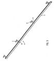
- erfindungsgemäße Haltevorrichtung in dreidimensionaler Darstellung;
- Fig. 4
- Halteleiste gemäß dem Stand der Technik.
- Fig. 1 zeigt im Querschnitt die Haltevorrichtung in Anlage an die Fahrzeugkarosse.
- Die Haltevorrichtung 1 besteht aus polymerem Material. Sie ist leistenförmig ausgeführt und wurde im Spritzgussverfahren hergestellt. In der dargestellten Ausführungsform verfügt die Haltevorrichtung 1 über einen im Wesentlichen U-förmigen Halteabschnitt 3 und einen im Wesentlichen T-förmigen Positionierabschnitt 4. Selbstverständlich kann die Haltevorrichtung mehr Halte- und Positionierabschnitte aufweisen, wobei sowohl der Halteabschnitt als auch der Positionierabschnitt andersartig geformt sein können. Halteabschnitt 3 und Positionierabschnitt 4 sind einstückig miteinander verbunden und bestehen aus dem gleichen Material. Die Verbindungsstelle ist dabei als Sollbruchstelle 5 ausgeführt. Der Schenkel des im Wesentlichen U-förmigen Halteabschnitts 3, der bei montiertem Halteabschnitt 3 der Fahrzeugkarosse 2 zugewandt ist, ist im Wesentlichen parallel zur Oberfläche der Fahrzeugkarosse 2 angeordnet. Zwischen dem der Fahrzeugkarosse 2 zugewandten Schenkel des im Wesentlichen U-förmigen Halteabschnitts 3 und dem im Wesentlichen parallel dazu verlaufenden Abschnitt der Fahrzeugkarosse 2 ist ein Klebeband 8 angeordnet, das den Halteabschnitt 3 mit der Fahrzeugkarosse 2 stoffschlüssig verbindet. An den Schenkel des im Wesentlichen U-förmigen Halteabschnitts 3, welcher der Fahrzeugkarosse 2 in montiertem Zustand zugewandt ist, schließt sich der Positionierabschnitt an 4, wobei der Verbindungsbereich eine bewusst hergestellte Materialschwächung aufweist, die als Sollbruchstelle 5 beim Abtrennen des Positionierabschnitts 4 vom Halteabschnitt 3 dient. Die Sollbruchstelle 5 ist dabei weiter vom gekrümmten Teil des Halteabschnitts 3 beabstandet als das Ende des Schenkels, welcher der Fahrzeugkarosse 2 im montierten Zustand des Halteabschnitts 3 abgewandt ist. Zudem ist die Sollbruchstelle 5 benachbart zu dem Bereich des Halteabschnitts 3 angeordnet, der stoffschlüssig mit der Oberfläche der Fahrzeugkarosse 2 verbunden ist. Der Teil des Positionierabschnitts 4, der sich an die Sollbruchstelle 5 anschließt, ergibt sich aus der Verlängerung des der der Fahrzeugkarosse 2 zugewandten Schenkels des Halteabschnitts 3. Von dieser Verlängerung zweigt ein Steg in im Wesentlichen senkrechter Richtung ab, der als Positionieranschlag 6 dient.
- Aus der Verlängerung des Schenkels des Halteabschnitts 3, welcher der Fahrzeugkarosse 2 im montierten Zustand des Halteabschnitts 3 zugewandt ist, ergibt sich an seinem Ende ein Kraftangriffshebel 7 zum Lösen des Positionierabschnitts vom montierten Halteabschnitt 3.
- Nachfolgend wird die Wirkungs- und Funktionsweise der Erfindung näher erläutert.
- Die Haltevorrichtung 1 wird zur Befestigung von Bauteilen an einer Fahrzeugkarosse 2 eingesetzt. Die Positionierung einer Haltevorrichtung an der Fahrzeugkarosse erfolgt bei ausschließlich geklebten Haltevorrichtungen mit Hilfe von an der Haltevorrichtung angebrachten Positionierhilfen, die sich auf einer Abstellung der Fahrzeugkarosse abstützen (siehe Fig. 4). Diese aus dem Stand der Technik bekannte Positionierhilfe ist dabei jedoch an definierte Gestaltungsformen der Fahrzeugkarosse derart gebunden, dass die Anlageseite der Haltevorrichtung senkrecht auf der Abstellung der Fahrzeugkarosse stehen muss, um eine eindeutige Positionierung der Haltevorrichtung zu gewährleisten. Bei der erfindungsgemäßen Haltevorrichtung 1 hingegen stützt sich der Halteabschnitt 3 nicht auf einer Abstellung der Fahrzeugkarosse 2 ab, sondern wird zunächst über den Positionieranschlag 6 mit einer Oberfläche der Fahrzeugkarosse 2 in Anlage gebracht. Der Positionieranschlag 6 liegt dabei zumindest abschnittsweise an der Oberfläche der Fahrzeugkarosse 2 an. Durch dieses Anlegen ergibt sich eine exakte Positionierung des Halteabschnitts 3 an der Fahrzeugkarosse 2. Im Anschluss an das Anlegen des Positionieranschlags 6 an die Fahrzeugkarosse 2 erfolgt das Entfernen des Liners, der das Klebeband 8 abdeckt, nach unten und der Halteabschnitt 3 der Haltevorrichtung 1 wird gegen die Fahrzeugkarosse 2 gedrückt, wodurch eine zumindest abschnittsweise stoffschlüssige Verbindung zwischen dem Halteabschnitt 3 und der Fahrzeugkarosse 2 resultiert. Nach dem Verbinden des Halteabschnitts 3 mit der Fahrzeugkarosse 2 an der durch den Positionieranschlag 6 definierten Position erfolgt die Aufbringung einer Kraft am Kraftangriffshebel 7 in der der Fahrzeugkarosse 2 abgewandten Richtung. Mit Beginn der Krafteinwirkung erfolgt ein Abheben des Positionierabschnitts 4 von der lackierten Fahrzeugkarosse 2, wodurch die Beschädigung des Lacks vermieden wird. Mit zunehmender Kraft bewegt sich der Positionierabschnitt 4 weiter in die der Fahrzeugkarosse 2 abgewandten Richtung, bis es zum Bruch im Bereich der Sollbruchstelle 5 kommt, wodurch der Positionierabschnitt 4 vom Halteabschnitt 3 abgelöst werden kann.
Claims (24)
- Haltevorrichtung (1) zur Befestigung eines Bauteils an einer Fahrzeugkarosse (2), die wenigstens einen Halteabschnitt (3) zur Befestigung des Bauteils aufweist, und die zumindest einen Positionierabschnitt (4) aufweist, der wenigstens an einem Punkt einer Fläche der Fahrzeugkarosse (2) zur Positionierung der Haltevorrichtung (1) an der Fahrzeugkarosse (2) zumindest abschnittsweise in Anlage bringbar ist, dadurch gekennzeichnet, dass der zumindest eine Positionierabschnitt nach erfolgter Positionierung und Montage der Haltevorrichtung (1) von dieser lösbar ist.
- Haltevorrichtung nach Anspruch 1, dadurch gekennzeichnet, dass diese aus einem polymeren Material besteht.
- Haltevorrichtung nach Anspruch 1 oder 2, dadurch gekennzeichnet, dass die Haltevorrichtung in einem Spritzgießverfahren hergestellt ist.
- Haltevorrichtung nach einem der vorangegangen Ansprüche, dadurch gekennzeichnet, dass die Haltevorrichtung leistenförmig ausgeführt ist.
- Haltevorrichtung nach einem der vorangegangenen Ansprüche, dadurch gekennzeichnet, dass der zumindest eine Halteabschnitt (3) bei montiertem Bauteil dieses zumindest abschnittsweise umgreift.
- Haltevorrichtung nach einem der vorangegangenen Ansprüche, dadurch gekennzeichnet, dass der zumindest eine Halteabschnitt (3) einen im Wesentlichen U-förmigen Querschnitt aufweist.
- Haltevorrichtung nach Anspruch 6, dadurch gekennzeichnet, dass der der Fahrzeugkarosse (2) im montiertem Zustand zugewandte Schenkel des Halteabschnitts (3) zumindest abschnittsweise parallel zur Oberfläche der Fahrzeugkarosse (2) anordnungsbar ist.
- Haltevorrichtung nach einem der vorangegangenen Ansprüche, dadurch gekennzeichnet, dass der Halteabschnitt (3) zumindest abschnittsweise stoffschlüssig mit der Oberfläche der Fahrzeugkarosse (2) verbunden ist.
- Haltevorrichtung nach einem der vorangegangenen Ansprüche, dadurch gekennzeichnet, dass dieser zwei oder mehr Halteabschnitte (3) aufweist.
- Haltevorrichtung nach einem der vorangegangenen Ansprüche, dadurch gekennzeichnet, dass die Haltevorrichtung leistenförmig ausgeführt ist und drei oder mehr Halteabschnitte (3) aufweist, wobei jeweils zwei benachbarte Halteabschnitte den gleichen Abstand zueinander aufweisen.
- Haltevorrichtung nach einem der vorangegangenen Ansprüche, dadurch gekennzeichnet, dass der zumindest eine Positionierabschnitt (4) einstückig mit dem Halteabschnitt (3) verbunden ist und aus dem gleichen Material besteht.
- Haltevorrichtung nach einem der vorangegangenen Ansprüche, dadurch gekennzeichnet, dass der zumindest eine Positionierabschnitt (4) einmalig lösbar mit dem Halteabschnitt (3) verbunden ist.
- Haltevorrichtung nach einem der vorangegangenen Ansprüche, dadurch gekennzeichnet, dass der zumindest eine Positionierabschnitt (4) mit dem Schenkel des Halteabschnitts (3) verbunden ist, der der Fahrzeugkarosse (2) in montiertem Zustand zugewandt ist.
- Haltevorrichtung nach einem der vorangegangenen Ansprüche, dadurch gekennzeichnet, dass der zumindest eine Positionierabschnitt (4) derart mit dem Halteabschnitt (3) verbunden ist, dass die Verbindungsstelle als Sollbruchstelle (5) ausgeführt ist.
- Haltevorrichtung nach Anspruch 14, dadurch gekennzeichnet, dass die Sollbruchstelle (5) weiter vom gekrümmten Teil des Halteabschnitts (3) beabstandet ist als das Ende des Schenkels, der der Fahrzeugkarosse (2) im montierten Zustand des Halteabschnitts (3) abgewandt ist.
- Haltevorrichtung nach Anspruch 14 oder 15, dadurch gekennzeichnet, dass die Sollbruchstelle (5) benachbart ist zu dem Bereich des Halteabschnitts (3), der stoffschlüssig mit der Oberfläche der Fahrzeugkarosse (2) verbunden ist.
- Haltevorrichtung nach einem der vorangegangenen Ansprüche, dadurch gekennzeichnet, dass der zumindest eine Positionierabschnitt (4) einen Positionieranschlag (6) aufweist.
- Haltevorrichtung nach Anspruch 17, dadurch gekennzeichnet, dass der Positionieranschlag (6) einen vorspringenden Steg aufweist, der zumindest abschnittsweise an einer Oberfläche der Fahrzeugkarosse (2) in Anlage bringbar ist.
- Haltevorrichtung nach Anspruch 18, dadurch gekennzeichnet, dass der vorspringende Steg im Wesentlichen senkrecht zu dem Teil des Positionierabschnitts (4) angeordnet ist, der mit dem Halteabschnitt (3) verbunden ist.
- Haltevorrichtung nach einem der vorangegangenen Ansprüche, dadurch gekennzeichnet, dass der zumindest eine Positionierabschnitt (4) einen Kraftangriffshebel (7) zum Lösen des Positionierabschnitts (4) vom montierten Halteabschnitt (3) aufweist.
- Haltevorrichtung nach Anspruch 20, dadurch gekennzeichnet, dass der Kraftangriffshebel (7) aus der Verlängerung des Teils des Positionierabschnitts (4) gebildet wird, der mit dem Halteabschnitt (3) verbunden ist.
- Haltevorrichtung nach einem der vorangegangenen Ansprüche, dadurch gekennzeichnet, dass die Haltevorrichtung (1) zwei oder mehr Positionierabschnitte (4) aufweist.
- Bauteil, das mit einer Haltevorrichtung nach einem der vorangegangenen Ansprüche an einer Fahrzeugkarosse angeordnet ist.
- Fahrzeug mit einer Haltevorrichtung nach einem der vorangegangenen Ansprüche.
Applications Claiming Priority (1)
| Application Number | Priority Date | Filing Date | Title |
|---|---|---|---|
| DE102005038801A DE102005038801A1 (de) | 2005-08-17 | 2005-08-17 | Haltevorrichtung, vorzugsweise zur Befestigung eines Bauteils an einer Fahrzeugkarosse |
Publications (2)
| Publication Number | Publication Date |
|---|---|
| EP1754632A1 EP1754632A1 (de) | 2007-02-21 |
| EP1754632B1 true EP1754632B1 (de) | 2008-01-09 |
Family
ID=37103266
Family Applications (1)
| Application Number | Title | Priority Date | Filing Date |
|---|---|---|---|
| EP06013778A Not-in-force EP1754632B1 (de) | 2005-08-17 | 2006-07-04 | Haltevorrichtung, vorzugsweise zur Befestigung eines Bauteils an einer Fahrzeugkarosse |
Country Status (4)
| Country | Link |
|---|---|
| EP (1) | EP1754632B1 (de) |
| AT (1) | ATE383280T1 (de) |
| DE (2) | DE102005038801A1 (de) |
| ES (1) | ES2299121T3 (de) |
Families Citing this family (1)
| Publication number | Priority date | Publication date | Assignee | Title |
|---|---|---|---|---|
| ES2461017B1 (es) * | 2012-11-15 | 2015-03-02 | Seat Sa | Método de fabricación de un conjunto de soporte y pantalla transparente de un material plástico |
Family Cites Families (3)
| Publication number | Priority date | Publication date | Assignee | Title |
|---|---|---|---|---|
| DE4137707A1 (de) * | 1991-11-15 | 1993-05-19 | Bayerische Motoren Werke Ag | Fahrzeugdach, insbesondere fuer einen personenkraftwagen |
| DE19753099B4 (de) * | 1997-11-29 | 2005-10-20 | Volkswagen Ag | Einrichtung zum lagegenauen manuellen Aufbringen eines Dekorelements auf einen Gegenstand |
| JP4416336B2 (ja) * | 2001-01-29 | 2010-02-17 | 株式会社ニフコ | モール取付け用クリップ及びモ−ル取付け構造 |
-
2005
- 2005-08-17 DE DE102005038801A patent/DE102005038801A1/de not_active Withdrawn
-
2006
- 2006-07-04 ES ES06013778T patent/ES2299121T3/es active Active
- 2006-07-04 AT AT06013778T patent/ATE383280T1/de not_active IP Right Cessation
- 2006-07-04 EP EP06013778A patent/EP1754632B1/de not_active Not-in-force
- 2006-07-04 DE DE502006000282T patent/DE502006000282D1/de active Active
Also Published As
| Publication number | Publication date |
|---|---|
| ATE383280T1 (de) | 2008-01-15 |
| DE102005038801A1 (de) | 2007-02-22 |
| DE502006000282D1 (de) | 2008-02-21 |
| EP1754632A1 (de) | 2007-02-21 |
| ES2299121T3 (es) | 2008-05-16 |
Similar Documents
| Publication | Publication Date | Title |
|---|---|---|
| DE102008005575A1 (de) | Kraftfahrzugschloss und Schlossgehäuse | |
| DE102015206751A1 (de) | Lösbare Befestigungsanordnung eines Stoßfängers mit einer Seitenwand bzw. einem Kotflügel eines Kraftfahrzeuges | |
| DE4026922C2 (de) | Halteklammer zur Befestigung von Bauteilen an Trägerplatten | |
| EP3529868B1 (de) | Verbindungsanordnung für die verbindung von zwei schaltschrankrahmengestellen | |
| DE102016204483B4 (de) | Befestigungselement mit mindestens einem Clip zur Herstellung einer Verbindung mit einem korrespondierenden Ansteckelement und Anordnung eines Befestigungselements an einem Ansteckelement | |
| DE112019004011T5 (de) | Montagesystem für ein Kastenprofil | |
| EP1754632B1 (de) | Haltevorrichtung, vorzugsweise zur Befestigung eines Bauteils an einer Fahrzeugkarosse | |
| DE102010028294B4 (de) | Positionierungsvorrichtung und Verfahren zur Herstellung einer Bauteilanordnung | |
| DE102010048956A1 (de) | Vorrichtung und Verfahren zur Befestigung eines mindestens eine Öffnung aufweisenden Bauteils an einem Trägerteil | |
| DE102005012610B4 (de) | Klemmhalter | |
| DE102015217463A1 (de) | Halter zur Befestigung an einem Strukturteil eines Kraftfahrzeuges sowie Anordnung eines Halters an einem Strukturteil eines Kraftfahrzeuges | |
| EP2295297A1 (de) | Vorrichtung zur lagegenauen Montagepositionierung von mindestens zwei Bauteilen zueinander | |
| EP1091132A2 (de) | Anordnung zur lösbaren Befestigung eines Bauteils an einer Wand | |
| WO2004022416A1 (de) | Hybridbauteil mit spritzguss-kunstoffverbindern für kraftfahrzeuge und verfahren zur seiner reparatur | |
| DE102007012481A1 (de) | Kochfeld mit einem Zierrahmen und einem damit verbundenen Montagerahmen | |
| DE102010031709A1 (de) | Verfahren zum Fügen von Bauteilen mittels Widerstandsschweißen sowie Fügeteil hierfür | |
| DE102010011686A1 (de) | Befestigungsmittel für ein Kraftfahrzeug | |
| DE102006021457B4 (de) | Metallverstärkter Kunststoffträger für ein Fahrzeug | |
| DE102004003907B4 (de) | Klips | |
| DE102016200408A1 (de) | Verfahren zum Herstellen einer Bauteilverbindung | |
| DE102015201358A1 (de) | Leuchtenanordnung für ein Kraftfahrzeug und Heckspoiler | |
| DE102020124120B4 (de) | Fixieranordnung zum temporären Fixieren eines Anbauteils an einer Fahrzeugkarosserie und ein Verfahren | |
| DE102010035369A1 (de) | Vorrichtung zur Anbringung eines Verkleidungsteils an einem Trägerteil | |
| DE4328107C1 (de) | Haltebacke für eine Rohrhalterung | |
| DE102017004202A1 (de) | Verfahren und Vorrichtung zum Herstellen einer Fügeverbindung zwischen zwei Bauteilen mittels Schnappverbindungselementen |
Legal Events
| Date | Code | Title | Description |
|---|---|---|---|
| PUAI | Public reference made under article 153(3) epc to a published international application that has entered the european phase |
Free format text: ORIGINAL CODE: 0009012 |
|
| AK | Designated contracting states |
Kind code of ref document: A1 Designated state(s): AT BE BG CH CY CZ DE DK EE ES FI FR GB GR HU IE IS IT LI LT LU LV MC NL PL PT RO SE SI SK TR |
|
| AX | Request for extension of the european patent |
Extension state: AL BA HR MK YU |
|
| 17P | Request for examination filed |
Effective date: 20070322 |
|
| GRAP | Despatch of communication of intention to grant a patent |
Free format text: ORIGINAL CODE: EPIDOSNIGR1 |
|
| AKX | Designation fees paid |
Designated state(s): AT BE BG CH CY CZ DE DK EE ES FI FR GB GR HU IE IS IT LI LT LU LV MC NL PL PT RO SE SI SK TR |
|
| GRAS | Grant fee paid |
Free format text: ORIGINAL CODE: EPIDOSNIGR3 |
|
| GRAA | (expected) grant |
Free format text: ORIGINAL CODE: 0009210 |
|
| AK | Designated contracting states |
Kind code of ref document: B1 Designated state(s): AT BE BG CH CY CZ DE DK EE ES FI FR GB GR HU IE IS IT LI LT LU LV MC NL PL PT RO SE SI SK TR |
|
| REG | Reference to a national code |
Ref country code: GB Ref legal event code: FG4D Free format text: NOT ENGLISH |
|
| REG | Reference to a national code |
Ref country code: CH Ref legal event code: EP |
|
| REG | Reference to a national code |
Ref country code: IE Ref legal event code: FG4D Free format text: LANGUAGE OF EP DOCUMENT: GERMAN |
|
| REF | Corresponds to: |
Ref document number: 502006000282 Country of ref document: DE Date of ref document: 20080221 Kind code of ref document: P |
|
| REG | Reference to a national code |
Ref country code: ES Ref legal event code: FG2A Ref document number: 2299121 Country of ref document: ES Kind code of ref document: T3 |
|
| PG25 | Lapsed in a contracting state [announced via postgrant information from national office to epo] |
Ref country code: SI Free format text: LAPSE BECAUSE OF FAILURE TO SUBMIT A TRANSLATION OF THE DESCRIPTION OR TO PAY THE FEE WITHIN THE PRESCRIBED TIME-LIMIT Effective date: 20080109 Ref country code: NL Free format text: LAPSE BECAUSE OF FAILURE TO SUBMIT A TRANSLATION OF THE DESCRIPTION OR TO PAY THE FEE WITHIN THE PRESCRIBED TIME-LIMIT Effective date: 20080109 |
|
| NLV1 | Nl: lapsed or annulled due to failure to fulfill the requirements of art. 29p and 29m of the patents act | ||
| PG25 | Lapsed in a contracting state [announced via postgrant information from national office to epo] |
Ref country code: LT Free format text: LAPSE BECAUSE OF FAILURE TO SUBMIT A TRANSLATION OF THE DESCRIPTION OR TO PAY THE FEE WITHIN THE PRESCRIBED TIME-LIMIT Effective date: 20080109 Ref country code: IS Free format text: LAPSE BECAUSE OF FAILURE TO SUBMIT A TRANSLATION OF THE DESCRIPTION OR TO PAY THE FEE WITHIN THE PRESCRIBED TIME-LIMIT Effective date: 20080509 Ref country code: FI Free format text: LAPSE BECAUSE OF FAILURE TO SUBMIT A TRANSLATION OF THE DESCRIPTION OR TO PAY THE FEE WITHIN THE PRESCRIBED TIME-LIMIT Effective date: 20080109 |
|
| GBV | Gb: ep patent (uk) treated as always having been void in accordance with gb section 77(7)/1977 [no translation filed] | ||
| PG25 | Lapsed in a contracting state [announced via postgrant information from national office to epo] |
Ref country code: BG Free format text: LAPSE BECAUSE OF FAILURE TO SUBMIT A TRANSLATION OF THE DESCRIPTION OR TO PAY THE FEE WITHIN THE PRESCRIBED TIME-LIMIT Effective date: 20080409 |
|
| ET | Fr: translation filed | ||
| PG25 | Lapsed in a contracting state [announced via postgrant information from national office to epo] |
Ref country code: PL Free format text: LAPSE BECAUSE OF FAILURE TO SUBMIT A TRANSLATION OF THE DESCRIPTION OR TO PAY THE FEE WITHIN THE PRESCRIBED TIME-LIMIT Effective date: 20080109 Ref country code: PT Free format text: LAPSE BECAUSE OF FAILURE TO SUBMIT A TRANSLATION OF THE DESCRIPTION OR TO PAY THE FEE WITHIN THE PRESCRIBED TIME-LIMIT Effective date: 20080609 Ref country code: LV Free format text: LAPSE BECAUSE OF FAILURE TO SUBMIT A TRANSLATION OF THE DESCRIPTION OR TO PAY THE FEE WITHIN THE PRESCRIBED TIME-LIMIT Effective date: 20080109 |
|
| REG | Reference to a national code |
Ref country code: IE Ref legal event code: FD4D |
|
| PG25 | Lapsed in a contracting state [announced via postgrant information from national office to epo] |
Ref country code: SE Free format text: LAPSE BECAUSE OF FAILURE TO SUBMIT A TRANSLATION OF THE DESCRIPTION OR TO PAY THE FEE WITHIN THE PRESCRIBED TIME-LIMIT Effective date: 20080409 Ref country code: IE Free format text: LAPSE BECAUSE OF FAILURE TO SUBMIT A TRANSLATION OF THE DESCRIPTION OR TO PAY THE FEE WITHIN THE PRESCRIBED TIME-LIMIT Effective date: 20080109 Ref country code: SK Free format text: LAPSE BECAUSE OF FAILURE TO SUBMIT A TRANSLATION OF THE DESCRIPTION OR TO PAY THE FEE WITHIN THE PRESCRIBED TIME-LIMIT Effective date: 20080109 Ref country code: DK Free format text: LAPSE BECAUSE OF FAILURE TO SUBMIT A TRANSLATION OF THE DESCRIPTION OR TO PAY THE FEE WITHIN THE PRESCRIBED TIME-LIMIT Effective date: 20080109 |
|
| PLBE | No opposition filed within time limit |
Free format text: ORIGINAL CODE: 0009261 |
|
| STAA | Information on the status of an ep patent application or granted ep patent |
Free format text: STATUS: NO OPPOSITION FILED WITHIN TIME LIMIT |
|
| PG25 | Lapsed in a contracting state [announced via postgrant information from national office to epo] |
Ref country code: RO Free format text: LAPSE BECAUSE OF FAILURE TO SUBMIT A TRANSLATION OF THE DESCRIPTION OR TO PAY THE FEE WITHIN THE PRESCRIBED TIME-LIMIT Effective date: 20080109 |
|
| 26N | No opposition filed |
Effective date: 20081010 |
|
| PG25 | Lapsed in a contracting state [announced via postgrant information from national office to epo] |
Ref country code: GB Free format text: LAPSE BECAUSE OF FAILURE TO SUBMIT A TRANSLATION OF THE DESCRIPTION OR TO PAY THE FEE WITHIN THE PRESCRIBED TIME-LIMIT Effective date: 20080109 |
|
| PG25 | Lapsed in a contracting state [announced via postgrant information from national office to epo] |
Ref country code: MC Free format text: LAPSE BECAUSE OF NON-PAYMENT OF DUE FEES Effective date: 20080731 |
|
| PG25 | Lapsed in a contracting state [announced via postgrant information from national office to epo] |
Ref country code: EE Free format text: LAPSE BECAUSE OF FAILURE TO SUBMIT A TRANSLATION OF THE DESCRIPTION OR TO PAY THE FEE WITHIN THE PRESCRIBED TIME-LIMIT Effective date: 20080109 |
|
| PG25 | Lapsed in a contracting state [announced via postgrant information from national office to epo] |
Ref country code: CY Free format text: LAPSE BECAUSE OF FAILURE TO SUBMIT A TRANSLATION OF THE DESCRIPTION OR TO PAY THE FEE WITHIN THE PRESCRIBED TIME-LIMIT Effective date: 20080109 |
|
| PG25 | Lapsed in a contracting state [announced via postgrant information from national office to epo] |
Ref country code: IT Free format text: LAPSE BECAUSE OF FAILURE TO SUBMIT A TRANSLATION OF THE DESCRIPTION OR TO PAY THE FEE WITHIN THE PRESCRIBED TIME-LIMIT Effective date: 20080109 |
|
| PG25 | Lapsed in a contracting state [announced via postgrant information from national office to epo] |
Ref country code: AT Free format text: LAPSE BECAUSE OF NON-PAYMENT OF DUE FEES Effective date: 20080704 |
|
| PG25 | Lapsed in a contracting state [announced via postgrant information from national office to epo] |
Ref country code: LU Free format text: LAPSE BECAUSE OF NON-PAYMENT OF DUE FEES Effective date: 20080704 Ref country code: BE Free format text: LAPSE BECAUSE OF NON-PAYMENT OF DUE FEES Effective date: 20080731 Ref country code: HU Free format text: LAPSE BECAUSE OF FAILURE TO SUBMIT A TRANSLATION OF THE DESCRIPTION OR TO PAY THE FEE WITHIN THE PRESCRIBED TIME-LIMIT Effective date: 20080710 |
|
| PG25 | Lapsed in a contracting state [announced via postgrant information from national office to epo] |
Ref country code: TR Free format text: LAPSE BECAUSE OF FAILURE TO SUBMIT A TRANSLATION OF THE DESCRIPTION OR TO PAY THE FEE WITHIN THE PRESCRIBED TIME-LIMIT Effective date: 20080109 |
|
| PG25 | Lapsed in a contracting state [announced via postgrant information from national office to epo] |
Ref country code: GR Free format text: LAPSE BECAUSE OF FAILURE TO SUBMIT A TRANSLATION OF THE DESCRIPTION OR TO PAY THE FEE WITHIN THE PRESCRIBED TIME-LIMIT Effective date: 20080410 |
|
| REG | Reference to a national code |
Ref country code: CH Ref legal event code: PL |
|
| PG25 | Lapsed in a contracting state [announced via postgrant information from national office to epo] |
Ref country code: LI Free format text: LAPSE BECAUSE OF NON-PAYMENT OF DUE FEES Effective date: 20100731 Ref country code: CH Free format text: LAPSE BECAUSE OF NON-PAYMENT OF DUE FEES Effective date: 20100731 |
|
| REG | Reference to a national code |
Ref country code: FR Ref legal event code: PLFP Year of fee payment: 10 |
|
| PGFP | Annual fee paid to national office [announced via postgrant information from national office to epo] |
Ref country code: CZ Payment date: 20150515 Year of fee payment: 10 |
|
| PGFP | Annual fee paid to national office [announced via postgrant information from national office to epo] |
Ref country code: FR Payment date: 20150513 Year of fee payment: 10 |
|
| PGFP | Annual fee paid to national office [announced via postgrant information from national office to epo] |
Ref country code: ES Payment date: 20150716 Year of fee payment: 10 Ref country code: DE Payment date: 20150731 Year of fee payment: 10 |
|
| PG25 | Lapsed in a contracting state [announced via postgrant information from national office to epo] |
Ref country code: CZ Free format text: LAPSE BECAUSE OF NON-PAYMENT OF DUE FEES Effective date: 20160704 |
|
| REG | Reference to a national code |
Ref country code: DE Ref legal event code: R119 Ref document number: 502006000282 Country of ref document: DE |
|
| PG25 | Lapsed in a contracting state [announced via postgrant information from national office to epo] |
Ref country code: FR Free format text: LAPSE BECAUSE OF NON-PAYMENT OF DUE FEES Effective date: 20160801 Ref country code: DE Free format text: LAPSE BECAUSE OF NON-PAYMENT OF DUE FEES Effective date: 20170201 |
|
| REG | Reference to a national code |
Ref country code: FR Ref legal event code: ST Effective date: 20170331 |
|
| PG25 | Lapsed in a contracting state [announced via postgrant information from national office to epo] |
Ref country code: ES Free format text: LAPSE BECAUSE OF NON-PAYMENT OF DUE FEES Effective date: 20160705 |
|
| REG | Reference to a national code |
Ref country code: ES Ref legal event code: FD2A Effective date: 20181204 |