EP1754660A2 - Sonde de ravitaillement en vol avec un tube flexible et extensible - Google Patents
Sonde de ravitaillement en vol avec un tube flexible et extensible Download PDFInfo
- Publication number
- EP1754660A2 EP1754660A2 EP06254165A EP06254165A EP1754660A2 EP 1754660 A2 EP1754660 A2 EP 1754660A2 EP 06254165 A EP06254165 A EP 06254165A EP 06254165 A EP06254165 A EP 06254165A EP 1754660 A2 EP1754660 A2 EP 1754660A2
- Authority
- EP
- European Patent Office
- Prior art keywords
- refueling
- tube
- boom
- flexible
- aircraft
- Prior art date
- Legal status (The legal status is an assumption and is not a legal conclusion. Google has not performed a legal analysis and makes no representation as to the accuracy of the status listed.)
- Granted
Links
Images


Classifications
-
- B—PERFORMING OPERATIONS; TRANSPORTING
- B64—AIRCRAFT; AVIATION; COSMONAUTICS
- B64D—EQUIPMENT FOR FITTING IN OR TO AIRCRAFT; FLIGHT SUITS; PARACHUTES; ARRANGEMENT OR MOUNTING OF POWER PLANTS OR PROPULSION TRANSMISSIONS IN AIRCRAFT
- B64D39/00—Refuelling during flight
- B64D39/04—Adaptations of hose construction
Definitions
- the present invention relates to an airborne mobile platform refueling boom having a flexible, pressure responsive end tube.
- Aircraft refueling booms are well known in the art; however, each is associated with its share of limitations.
- Figure 1 depicts a tail section of the aircraft 20 equipped with an extendible rigid aircraft refueling boom 10 that suffers from several limitations.
- the refueling boom 10 can withstand only a limited amount of in-flight movement during the actual refueling process when the nozzle 80 resides within a receiver aircraft (not shown).
- the refueling boom 10 may undergo undesirable stress at any of a multitude of boom locations such as at the point where the boom upper section 30 meets the aircraft 20, where the retractable boom portion 70 retracts into the boom lower section 60, or where the nozzle 80 inserts into a receiver aircraft (not shown). Regardless of whether such in-flight movement is vertical or horizontal, the refueling boom 10 may undergo undesirable stress at the noted locations. If boom overstressing occurs, repairing the boom requires removal of the complete refueling boom 10 from the aircraft 20.
- While overstressing of the boom may result while physically manipulating the boom during a refueling event, damage of the boom at the conclusion of refueling may also occur due to a fluid shock load. More specifically, if the maximum refueling pressure of the refueling boom is exceeded, then the boom may suffer the effects of "water-hammer" during receiver aircraft refueling. In order to lessen the effects of water-hammer, an internal fuel dynamic shock absorber bladder 40 is typically required in existing refueling booms. However, repairing and replacing such a bladder 40 is time consuming and expensive because removal of the entire refueling boom 10 is required for such a repair. Additionally, replacement or repair of the bladder 40 also results in the aircraft being out of service for an extended period of time since extensive repair hours are generally necessary. This aircraft downtime increases the overall cost of repair of the bladder 40 and the life-cycle cost of the refueling boom.
- the refueling boom is typically used in connection with a refueling tanker aircraft, although the refueling boom could be employed with any form of refueling mobile platform, and is therefore not limited to use with just aircraft.
- the refueling boom utilizes an upper boom tube that connects to an aircraft underside, a lower boom tube that connects to the upper boom tube, and a removable flexible tube with a nozzle that is connected to the lower boom tube.
- the flexible tube is bendable to accommodate movement of the tanker aircraft relative to a receiver mobile aircraft during in-flight refueling of the receiver aircraft. Also, when the flexible tube bends, it signifies to a boom operator that the flexible tube is under a stress load.
- the flexible tube is also expandable about its longitudinal axis to absorb loading forces due to the conservation of momentum of the fuel being shut off or on during a refueling event.
- the expandable, flexible tube eliminates shock loads and pressure spikes in other areas of the refueling boom due to the expandability of the flexible tube.
- a ruddervator is attached to the refueling boom to permit aerial control of the upper, lower and flexible tubes prior to and during refueling.
- the flexible tube is individually removable from the refueling boom, without removing the balance of the boom from the aircraft, to facilitate convenient and cost-effective maintenance. The removal of the flexible tube may be by a threaded connection, a push-on pull-off type connection, or other suitable mechanical quick disconnect method.
- the entire refueling boom tube is either a rigid tube or a flexible, bendable hose with an additional end hose or tube that is expandable, resilient and equipped to be quickly connected and disconnected to the main refueling boom tube.
- a flexible, bendable and expandable tube eliminates the need for an internal shock bladder of prior art refueling booms.
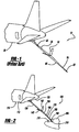
- Figure 1 is a perspective view of an aircraft tail section employing a rigid refueling boom with an internal shock bladder, according to the prior art
- Figure 2 is a perspective view of an aircraft tail section employing a refueling boom with a flexible extendable air refueling boom tube according to the teachings of the present invention
- Figure 3 is a perspective view of a refueling boom with a flexible, expandable, and extendable air refueling boom end tube according to the teachings of the present invention
- Figure 4 is a perspective view of a flexible, expandable air refueling boom end tube according to the teachings of the present invention
- Figure 5 is a perspective view of a flexible, expandable air refueling boom end tube in an expanded condition according to the teachings of the present invention
- Figure 6 is a perspective view of a flexible boom tube having a flexible, expandable air refueling boom end tube according to a second embodiment of the teachings of the present invention.
- Figure 7 is a perspective view of a basket style fuel receptacle to which the flexible air refueling boom tube of the present invention can be applied.
- An in-flight refueling boom is generally depicted in Figure 2 at reference numeral 100.
- a first end of the refueling boom 100 attaches to a tanker aircraft 110, usually at the aircraft tail section 120.
- the connection of the refueling boom 100 to the tanker aircraft 110 is normally a rigid connection that permits movement in the vertical direction, that is, a vertical plane through which the refueling boom 100 can move or pivot.
- the refueling boom 100 is moved, known as "flying" the boom, by an operator, known as a “boomer”, in a vertical plane by manipulating control vanes 140, 145, referred to throughout the following discussion as “ruddervators” 140, 145.
- the control vanes 140, 145 are termed “ruddervators” 140, 145 because they act as a rudder and an elevator for maneuvering the refueling boom 100 when the refueling boom 100 is maneuvered into position over a receiver mobile platform, such as a receiver aircraft 200.
- Figure 2 and Figure 3 depict a main refueling tube 130 that is attached to the tanker aircraft 110.
- the main refueling tube 130 On the main refueling tube 130 are the attached ruddervators 140, 145, which are used to maneuver the refueling boom 100 into position for refueling the receiver aircraft 200.
- the refueling boom 100 is easily maneuvered in a vertical plane, the refueling boom can also be maneuvered laterally to a small degree.
- the refueling boom 100 is supported from a fuselage 112 of the tanker aircraft 110 and maneuvered over a receiver aircraft 200 so that the receiver aircraft 200 can receive liquid fuel from the supply or tanker aircraft 110.
- the refueling boom 100 is positioned over, yet slightly in front of, the receiver aircraft 200 using the ruddervators 140, 145.
- the retractable refueling tube 160 may be extended from within a distal end of the main refueling tube 130, relative to the tanker aircraft 110.
- the rigid retractable refueling tube 160 has a connection portion 170 that is used to connect the retractable refueling tube 160 and a flexible refueling tube 180.
- connection portion 170 may be any acceptable means of coupling two fluid-carrying tubes.
- a threaded connection may be used such that the flexible refueling tube 180 may have male or female threads on an end while the retractable refueling tube 160 would have the opposite of either male or female threads.
- the connection method could also be a push-pull type of quick connection apparatus such that the flexible refueling tube 180 could push onto the retractable refueling tube 160 for coupling. These connection methods would allow for the advantage of a quick connection of the flexible refueling tube 180 to the end of the retractable refueling tube 160 to facilitate maintenance, such as nozzle replacement, on the flexible refueling tube 180, or quick replacement of the flexible refueling tube 180 upon completion of its life cycle.
- a nozzle 190 At the end of the flexible refueling tube 180 opposite to the connection portion 170, is a nozzle 190.
- the nozzle 190 permits the flexible refueling tube 180 to lock into the receiver aircraft 200 to transfer fuel to the receiver aircraft 200.
- the receiver aircraft 200 has a receiver area 215 that contains a nozzle receiver 210, also known as a nozzle dock, for securely receiving the nozzle 190.
- the flexible refueling tube 180 permits the nozzle 190 to remain in the nozzle receiver 210 even when the tanker aircraft 110 is moving vertically to the extent permissible according to the flexible limit of the flexible refueling tube 180.
- an advantage of the flexible refueling tube 180 is that either the tanker aircraft 110 or the receiver aircraft 200 can move in a vertical plane while refueling is taking place without jeopardizing the integrity of the refueling operation. Furthermore, the tanker aircraft 110 may also move laterally, or horizontally, since the flexible refueling tube 180 permits movement in both planes. This is a significant advantage over prior art refueling booms that normally have very limited horizontal movement capabilities. Additionally, the flexible refueling tube 180 will permit movement from the nozzle receiver 210 location in nearly any direction. To elaborate, once the nozzle 190 is connected to the nozzle receiver 210, the tanker aircraft 110 is free to move laterally relative to the original longitudinal hook-up axis of the refueling boom 100. Finally, because the flexible refueling tube 180 is flexible, curvilinear motion of the tanker aircraft relative to the nozzle receiver 210 is also possible.
- the flexible refueling tube 180 Although various directions of motion are permitted by the flexible refueling tube 180, one advantage of the flexible refueling tube 180 over existing refueling tubes is the ability of a boomer to visually witness the bending and subsequently eliminate the bending by flying the boom to a different position relative to the nozzle receiver 210. Because of such an advantage, the flexible refueling tube 180 also eliminates the need for sensors used in conjunction with a conventional automatic load alleviation system (ALAS) (not shown) on the tanker aircraft 110.
- ALAS automatic load alleviation system
- An optional ALAS monitors stresses and loading in existing refueling booms during in flight refueling since such stresses and loading can not be accurately gauged by the naked eye by simply viewing a rigid tube.
- Figure 3 depicts the flexible refueling tube 180 in a straight condition
- Figure 4 depicts the flexible refueling tube 180 in a bent condition
- Figure 5 depicts the flexible refueling tube 180 in an expanded condition
- Figure 4 depicts the flexible nature of the flexible refueling tube 180 when it is placed under a load that is not coincident with the longitudinal axis of the flexible refueling tube 180.
- the flexible refueling tube 180 is permitted to flex in response to a situation in which the tanker aircraft 110 may move in a vertical plane, horizontal plane, or a combination of such, relative to the nozzle receiver 210.
- nozzle loads and stresses are significantly reduced or eliminated.
- FIG. 5 depicts the expansive nature of the flexible refueling tube 180, which illustrates another advantage of the present invention.
- liquid fuel is not compressible and as a result, any energy that is applied to it is instantly transmitted to surrounding structure. This energy becomes dynamic in nature when a force such as a quick closing valve applies velocity to the fluid.
- Surge or "water hammer” is the result of a sudden change in liquid velocity. Water hammer usually occurs when a transfer system is quickly started, stopped or is forced to make a rapid change in direction. These events can cause undesired stresses to be placed on a liquid fuel transfer system such as an in-flight refueling boom.
- the flexible refueling tube 180 is designed to absorb the shock associated with any water hammer that occurs during an in-flight refueling operation.
- the flexible refueling tube 180 When the fuel flow is shut off during refueling, the fuel pressure spike resulting from the momentum of the fuel mass is absorbed and reduced by the expansion of the flexible refueling tube 180.
- the flexible refueling tube 180 As depicted in Figure 5, the flexible refueling tube 180 is seen in its expanded (i.e., albeit exaggerated) condition, while its unexpanded geometry is depicted in phantom at 230.
- Such an expansion occurs between the quick-connect threaded end 220, which connects to the retractable refueling tube 160, and the nozzle 190, which connects to the nozzle receiver 210.
- the primary cause of water hammer during in-flight refueling is by closing a fuel valve, whether manually or automatically.
- a fuel valve may be located at the aircraft, where the refueling boom 100 meets the aircraft 110, or at the nozzle receiver 210 of the receiver aircraft 200.
- a fuel valve that quickly closes, depending upon valve size and system conditions, may cause an abrupt stoppage of fuel flow that generates a fuel pressure spike or acoustic wave in the refueling boom 100.
- the fuel pressure spike can be a multitude of times higher than the fuel system working pressure during steady-state refueling.
- the expandable, flexible refueling tube 180 will expand like a balloon in accordance with the pressure changes in such a re-fueling event when a valve is suddenly opened or closed, relative to the steady-state flow. For instance, steady-state refueling pressure is normally below 55 psi; however, the spike pressure in the refueling boom 100, which results when a valve is suddenly opened or closed, may approach 240 psi.
- the pressure at which the expandable, flexible refueling tube 180 may begin to expand may be just above 55 psi.
- the actual fuel pressure at which the expandable, flexible tube 180 may begin to expand may vary with the material used for the expandable, flexible refueling tube 180.
- the expandable, flexible refueling tube 180 can be made of any rubber or rubber-like material that is suitable for the transfer of liquid aircraft fuel.
- an advantage of the expandable, flexible tube 180 is the elimination of the need for a separate internal bladder that is typically used with existing refueling booms. This also eliminates the need to remove a traditional boom from an aircraft to replace such a bladder, and furthermore, permits quick and easy connection of a replacement expandable, flexible refueling tube 180 according to the present invention.
- Figure 6 depicts a second embodiment of the present invention.
- a refueling boom tube 400 is connected to the aircraft 420 and may entail an upper boom tube 410 and a lower boom tube 430.
- the lower boom tube 430 attaches to the upper boom tube 410 in one of several possible methods such as a threaded connection or a push-on pull-off type connection, or other suitable mechanical quick disconnect method.
- a nozzle 450 attaches to the lower boom tube 430 and is used in the same fashion as in the first embodiment, that is, the nozzle 450 is receivable by a nozzle receiver of an airborne mobile platform that is in need of refueling.
- the upper boom tube 410 may be made of a flexible, bendable material, such as rubber, that is suited to carrying liquid aviation fuel.
- the upper boom tube 410 may be made from a semi-rigid rubber.
- These upper and lower boom tubes 410, 430 may be made of the same rubber material or rubber materials having different rigidity and expansion characteristics. This is in contrast to the rigid upper boom tube 150 of the first embodiment which may be made of metal.
- the lower boom tube 430 of the second embodiment may be a resilient rubber or rubber-like material that is capable of bending, expanding, and absorbing shock loads due to the fuel momentum pressure accumulation situation created in the lower boom tube 430 during the opening or closing of fuel valves during the refueling of an in-flight aircraft.
- the upper and lower boom tubes 410, 430 may be connectable by a quick connection joint 440, such as a threaded connection or push-on pull-off type connection.
- a quick connection joint 440 such as a threaded connection or push-on pull-off type connection.
- the lower boom tube 430 performs in the same manner as the expandable, flexible refueling tube 180 of the first embodiment.
- a general advantage of the second embodiment is the total overall flexibility of the refueling boom tube 400 when the upper boom tube 410 is connected to the lower boom tube 430. Another advantage is that the refueling boom tube 400 gains even greater flexibility than existing boom tubes, and the refueling boom 10 of the first embodiment, because both sections of the refueling boom tube 400 are flexible. This permits greater variation in the relative positions of the airborne mobile platforms during a refueling operation.
- Figure 7 depicts a "capturing" or “basket” refueling system that receives fuel during refueling in a slightly different manner compared to the "flying boom" and nozzle system depicted in Figures 2 and 3.
- the teachings of the present invention may be used with either a nozzle receiver 210 or a basket type system.
- a rotorcraft (e.g. helicopter) 300 extends a rigid refueling boom 320 from a refueling boom receptacle 310.
- the rigid refueling boom 320 has a refueling basket 330 that receives the extendable, flexible refueling tube 180, 430 according to the first and second embodiments.
- the alignment of the tanker aircraft need only be changed to accommodate such a refueling basket 330.
Landscapes
- Engineering & Computer Science (AREA)
- Aviation & Aerospace Engineering (AREA)
- Rigid Pipes And Flexible Pipes (AREA)
- Loading And Unloading Of Fuel Tanks Or Ships (AREA)
- Air Transport Of Granular Materials (AREA)
- Sampling And Sample Adjustment (AREA)
- Fluid-Damping Devices (AREA)
- Jib Cranes (AREA)
Applications Claiming Priority (1)
| Application Number | Priority Date | Filing Date | Title |
|---|---|---|---|
| US11/208,343 US20070040065A1 (en) | 2005-08-19 | 2005-08-19 | Flexible refueling boom extendable tube |
Publications (3)
| Publication Number | Publication Date |
|---|---|
| EP1754660A2 true EP1754660A2 (fr) | 2007-02-21 |
| EP1754660A3 EP1754660A3 (fr) | 2007-12-05 |
| EP1754660B1 EP1754660B1 (fr) | 2009-03-11 |
Family
ID=37401011
Family Applications (1)
| Application Number | Title | Priority Date | Filing Date |
|---|---|---|---|
| EP06254165A Active EP1754660B1 (fr) | 2005-08-19 | 2006-08-08 | Sonde de ravitaillement en vol avec un tube flexible et extensible |
Country Status (5)
| Country | Link |
|---|---|
| US (1) | US20070040065A1 (fr) |
| EP (1) | EP1754660B1 (fr) |
| AT (1) | ATE425084T1 (fr) |
| DE (1) | DE602006005563D1 (fr) |
| ES (1) | ES2322292T3 (fr) |
Cited By (2)
| Publication number | Priority date | Publication date | Assignee | Title |
|---|---|---|---|---|
| CN103192993A (zh) * | 2013-03-28 | 2013-07-10 | 西北工业大学 | 一种有小翼的空中加油机锥套 |
| EP2243705A3 (fr) * | 2009-04-20 | 2013-08-28 | Flight Refuelling Limited | Appareil de ravitaillement aérien |
Families Citing this family (8)
| Publication number | Priority date | Publication date | Assignee | Title |
|---|---|---|---|---|
| ES2378007B1 (es) * | 2009-02-12 | 2013-01-31 | Eads Construcciones Aeronáuticas, S.A. | Conjunto de control y mando para aeronave. |
| US8485474B2 (en) * | 2010-08-31 | 2013-07-16 | The Boeing Company | Aerial refueling boom nozzle with integral pressure regulation |
| CN105083571A (zh) * | 2015-09-08 | 2015-11-25 | 天津市天舞科技有限公司 | 一种可转动桁杆式直升机空中受油装置 |
| US10343788B2 (en) * | 2017-09-26 | 2019-07-09 | The Boeing Company | Telescoping refueling boom control systems and methods |
| US11691753B2 (en) * | 2019-11-11 | 2023-07-04 | Textron Innovations Inc. | Systems and methods for aerial aircraft resupply |
| CN112896533A (zh) * | 2021-03-12 | 2021-06-04 | 中航西飞民用飞机有限责任公司 | 一种飞机加油杆系统及加油方法 |
| US12503250B2 (en) * | 2023-01-31 | 2025-12-23 | The Boeing Company | Systems and method to determine connection of a boom with a receiver aircraft |
| CN118083144B (zh) * | 2024-04-18 | 2024-08-09 | 中国空气动力研究与发展中心计算空气动力研究所 | 飞行器空中对接装置及方法 |
Family Cites Families (60)
| Publication number | Priority date | Publication date | Assignee | Title |
|---|---|---|---|---|
| US2663523A (en) * | 1949-08-02 | 1953-12-22 | Boeing Co | Aircraft interconnecting mechanism |
| GB724092A (en) * | 1951-07-16 | 1955-02-16 | Boeing Co | Aircraft interconnecting mechanism |
| US2859002A (en) * | 1954-03-05 | 1958-11-04 | Boeing Co | Airfoil aircraft interconnecting boom |
| US3091419A (en) * | 1957-01-14 | 1963-05-28 | Schulz Tool & Mfg Co | Aircraft in-flight refueling system |
| US3108769A (en) * | 1961-09-18 | 1963-10-29 | Schulz Tool & Mfg Co | Ring wing drogue |
| GB1054110A (fr) * | 1963-04-19 | |||
| US3665967A (en) * | 1970-01-16 | 1972-05-30 | Western Co Of North America | Supercharge hose |
| US3874417A (en) * | 1973-05-24 | 1975-04-01 | Robert B Clay | Pneumatic pump surge chamber |
| US4025193A (en) * | 1974-02-11 | 1977-05-24 | The Boeing Company | Apparatus suitable for use in orienting aircraft in-flight for refueling or other purposes |
| US3917196A (en) * | 1974-02-11 | 1975-11-04 | Boeing Co | Apparatus suitable for use in orienting aircraft flight for refueling or other purposes |
| US4095761A (en) * | 1976-09-29 | 1978-06-20 | The Boeing Company | Aerial refueling spoiler |
| US4072283A (en) * | 1976-12-17 | 1978-02-07 | The Boeing Company | Aerial refueling boom articulation |
| US4129270A (en) * | 1977-06-13 | 1978-12-12 | The Boeing Company | Air refueling boom pivot gimbal arrangements |
| US4231536A (en) * | 1977-10-11 | 1980-11-04 | The Boeing Company | Airfoil for controlling refueling boom |
| US4519560A (en) * | 1977-10-11 | 1985-05-28 | The Boeing Company | Airfoil for controlling refueling boom |
| US4158885A (en) * | 1977-11-09 | 1979-06-19 | The Boeing Company | Guidance-light display apparatus and method for in-flight link-up of two aircraft |
| US4160534A (en) * | 1977-12-30 | 1979-07-10 | The Boeing Company | Operating station for aircraft refueling boom |
| US4264044A (en) * | 1977-12-30 | 1981-04-28 | The Boeing Company | Operating station for aircraft refueling boom |
| US4170773A (en) * | 1978-05-05 | 1979-10-09 | The Boeing Company | Precision approach sensor system for aircraft |
| US4298176A (en) * | 1979-03-01 | 1981-11-03 | Mcdonnell Douglas Corporation | Remote refueling station |
| US4586683A (en) * | 1979-03-12 | 1986-05-06 | Mcdonnell Douglas Corporation | Rolling aerial refueling boom |
| US4257703A (en) * | 1979-03-15 | 1981-03-24 | The Bendix Corporation | Collision avoidance using optical pattern growth rate |
| US4510525A (en) * | 1982-03-23 | 1985-04-09 | The United States Of America As Represented By The Secretary Of The Air Force | Stereoscopic video imagery generation |
| US4633376A (en) * | 1985-07-15 | 1986-12-30 | The Boeing Company | Advanced fuel receptacle lighting system for aerial refueling |
| US4834531A (en) * | 1985-10-31 | 1989-05-30 | Energy Optics, Incorporated | Dead reckoning optoelectronic intelligent docking system |
| US4792107A (en) * | 1986-07-31 | 1988-12-20 | The Boeing Company | Airship telescopic boom |
| GB2228771A (en) * | 1989-01-27 | 1990-09-05 | Smr Technologies Inc | Refuelling surge boot |
| US5267328A (en) * | 1990-01-22 | 1993-11-30 | Gouge James O | Method for selecting distinctive pattern information from a pixel generated image |
| US5249128A (en) * | 1990-11-16 | 1993-09-28 | Texas Instruments Incorporated | System and method for determining the distance to an energy emitting object |
| DE69330513D1 (de) * | 1992-03-20 | 2001-09-06 | Commw Scient Ind Res Org | Gegenstands-überwachungsystem |
| US5479526A (en) * | 1993-03-23 | 1995-12-26 | Martin Marietta | Pixel designator for small objects |
| FR2705082B1 (fr) * | 1993-05-12 | 1995-08-04 | Aerospatiale | Système de ravitaillement en vol. |
| US5809658A (en) * | 1993-09-29 | 1998-09-22 | Snap-On Technologies, Inc. | Method and apparatus for calibrating cameras used in the alignment of motor vehicle wheels |
| WO1995034044A1 (fr) * | 1994-06-09 | 1995-12-14 | Kollmorgen Instrument Corporation | Systeme optique stereoscopique de controle automatique et/ou d'alignement de dispositifs d'affichage sur une chaine de fabrication |
| KR0174454B1 (ko) * | 1995-06-30 | 1999-03-20 | 배순훈 | 특징점 기반 움직임 보상에서의 에지 검출, 세선화 방법 및 장치 |
| US5568136A (en) * | 1995-09-05 | 1996-10-22 | Hochstein; Peter A. | Method and apparatus for identifying and measuring the distance between vehicles |
| US5785276A (en) * | 1995-12-22 | 1998-07-28 | The Boeing Company | Actuated roll axis aerial refueling boom |
| DE19836681B4 (de) * | 1997-09-19 | 2008-03-27 | Carl Zeiss Ag | Stereoskopisches Aufnahme- und Wiedergabesystem |
| US6004639A (en) * | 1997-10-10 | 1999-12-21 | Fiberspar Spoolable Products, Inc. | Composite spoolable tube with sensor |
| US5906336A (en) * | 1997-11-14 | 1999-05-25 | Eckstein; Donald | Method and apparatus for temporarily interconnecting an unmanned aerial vehicle |
| US6191809B1 (en) * | 1998-01-15 | 2001-02-20 | Vista Medical Technologies, Inc. | Method and apparatus for aligning stereo images |
| DE19807702A1 (de) * | 1998-02-24 | 1999-08-26 | Bosch Gmbh Robert | Dämpferelement für ein Kraftstoffversorgungssystem |
| US5996939A (en) * | 1998-08-28 | 1999-12-07 | The Boeing Company | Aerial refueling boom with translating pivot |
| JP3596314B2 (ja) * | 1998-11-02 | 2004-12-02 | 日産自動車株式会社 | 物体端の位置計測装置および移動体の通行判断装置 |
| US6778216B1 (en) * | 1999-03-25 | 2004-08-17 | Texas Instruments Incorporated | Method and apparatus for digital camera real-time image correction in preview mode |
| US6282301B1 (en) * | 1999-04-08 | 2001-08-28 | The United States Of America As Represented By The Secretary Of The Army | Ares method of sub-pixel target detection |
| JP2001213254A (ja) * | 2000-01-31 | 2001-08-07 | Yazaki Corp | 車両用側方監視装置 |
| AU8146801A (en) * | 2000-03-10 | 2001-09-24 | Erickson Air Crane Inc | Fluid loading system |
| US6250287B1 (en) * | 2000-03-14 | 2001-06-26 | Brunswick Corporation | Fuel delivery system for a marine engine |
| US6768509B1 (en) * | 2000-06-12 | 2004-07-27 | Intel Corporation | Method and apparatus for determining points of interest on an image of a camera calibration object |
| JP4159794B2 (ja) * | 2001-05-02 | 2008-10-01 | 本田技研工業株式会社 | 画像処理装置及び方法 |
| US6651933B1 (en) * | 2002-05-01 | 2003-11-25 | The Boeing Company | Boom load alleviation using visual means |
| US6779758B2 (en) * | 2002-05-07 | 2004-08-24 | Smiths Aerospace, Inc. | Boom deploy system |
| US6752357B2 (en) * | 2002-05-10 | 2004-06-22 | The Boeing Company | Distance measuring using passive visual means |
| US7209161B2 (en) * | 2002-07-15 | 2007-04-24 | The Boeing Company | Method and apparatus for aligning a pair of digital cameras forming a three dimensional image to compensate for a physical misalignment of cameras |
| US7171028B2 (en) * | 2002-11-22 | 2007-01-30 | The Boeing Company | Method and apparatus for covertly determining the rate of relative motion between two objects |
| US6994294B2 (en) * | 2003-08-29 | 2006-02-07 | Smiths Aerospace, Inc. | Stabilization of a drogue body |
| US7281687B2 (en) * | 2004-07-14 | 2007-10-16 | The Boeing Company | In-flight refueling system and method for facilitating emergency separation of in-flight refueling system components |
| US6948479B1 (en) * | 2004-09-01 | 2005-09-27 | Delphi Technologies, Inc. | Inline pulsation damper system |
| US7147186B2 (en) * | 2004-11-18 | 2006-12-12 | The Boeing Company | Interoperable aerial refueling apparatus and methods |
-
2005
- 2005-08-19 US US11/208,343 patent/US20070040065A1/en not_active Abandoned
-
2006
- 2006-08-08 EP EP06254165A patent/EP1754660B1/fr active Active
- 2006-08-08 DE DE602006005563T patent/DE602006005563D1/de active Active
- 2006-08-08 AT AT06254165T patent/ATE425084T1/de not_active IP Right Cessation
- 2006-08-08 ES ES06254165T patent/ES2322292T3/es active Active
Cited By (2)
| Publication number | Priority date | Publication date | Assignee | Title |
|---|---|---|---|---|
| EP2243705A3 (fr) * | 2009-04-20 | 2013-08-28 | Flight Refuelling Limited | Appareil de ravitaillement aérien |
| CN103192993A (zh) * | 2013-03-28 | 2013-07-10 | 西北工业大学 | 一种有小翼的空中加油机锥套 |
Also Published As
| Publication number | Publication date |
|---|---|
| ES2322292T3 (es) | 2009-06-18 |
| EP1754660A3 (fr) | 2007-12-05 |
| DE602006005563D1 (de) | 2009-04-23 |
| EP1754660B1 (fr) | 2009-03-11 |
| US20070040065A1 (en) | 2007-02-22 |
| ATE425084T1 (de) | 2009-03-15 |
Similar Documents
| Publication | Publication Date | Title |
|---|---|---|
| US7665479B2 (en) | Aerial refueling system | |
| EP1754660B1 (fr) | Sonde de ravitaillement en vol avec un tube flexible et extensible | |
| US7938369B2 (en) | Method and apparatus for aerial fuel transfer | |
| US7472868B2 (en) | Systems and methods for controlling an aerial refueling device | |
| US7188807B2 (en) | Refueling booms with multiple couplings and associated methods and systems | |
| US8439311B2 (en) | Aerial refueling boom and boom pivot | |
| EP2611691B1 (fr) | Ajutage de perche de ravitaillement aérien avec régulation de pression intégrale | |
| US7637458B2 (en) | Systems and methods for providing back-up hydraulic power for aircraft, including tanker aircraft | |
| CN112706931A (zh) | 无人机燃油供油系统及供油、加油控制方法 | |
| US2879016A (en) | In-flight refueling assembly | |
| US3319979A (en) | Quick attach and release fluid coupling assembly | |
| EP1780123A2 (fr) | Systèmes et procédés pour réduire des charges provenant de chocs de pression dans des tuyaux, y compris des tuyaux pour le ravitaillement d'avions | |
| EP2902326A1 (fr) | Système de ravitaillement en carburant cryogénique | |
| EP3484762A1 (fr) | Système d'accouplement destiné au transfert d'hydrocarbures en haute mer | |
| EP1824734A1 (fr) | Systeme de ravitaillement en vol, dispositif a vessie et procede pour empecher les oscillations dans les composants de systeme de ravitaillement en vol | |
| EP1894840A1 (fr) | Arrangement intelligent d'extrémité de perche de ravitaillement en vol | |
| CN214190133U (zh) | 无人机燃油供油系统 | |
| US8590840B2 (en) | Boom force absorber systems and methods for aerial refueling | |
| US2761701A (en) | Severable duct joints with plural universal connections | |
| CN209290667U (zh) | 雷达罩开启设备 | |
| EP3362362B1 (fr) | Couplage de ravitaillement en vol à faible force de prise | |
| EP2902687B1 (fr) | Connecteur cryogénique | |
| RU2841416C2 (ru) | Выпускная система | |
| EP3527489A1 (fr) | Système hydraulique pour aéronef | |
| CN115539746A (zh) | 一种耐高压柔性注水接头 |
Legal Events
| Date | Code | Title | Description |
|---|---|---|---|
| PUAI | Public reference made under article 153(3) epc to a published international application that has entered the european phase |
Free format text: ORIGINAL CODE: 0009012 |
|
| 17P | Request for examination filed |
Effective date: 20060817 |
|
| AK | Designated contracting states |
Kind code of ref document: A2 Designated state(s): AT BE BG CH CY CZ DE DK EE ES FI FR GB GR HU IE IS IT LI LT LU LV MC NL PL PT RO SE SI SK TR |
|
| AX | Request for extension of the european patent |
Extension state: AL BA HR MK YU |
|
| PUAL | Search report despatched |
Free format text: ORIGINAL CODE: 0009013 |
|
| AK | Designated contracting states |
Kind code of ref document: A3 Designated state(s): AT BE BG CH CY CZ DE DK EE ES FI FR GB GR HU IE IS IT LI LT LU LV MC NL PL PT RO SE SI SK TR |
|
| AX | Request for extension of the european patent |
Extension state: AL BA HR MK YU |
|
| 17Q | First examination report despatched |
Effective date: 20080605 |
|
| AKX | Designation fees paid |
Designated state(s): AT BE BG CH CY CZ DE DK EE ES FI FR GB GR HU IE IS IT LI LT LU LV MC NL PL PT RO SE SI SK TR |
|
| GRAP | Despatch of communication of intention to grant a patent |
Free format text: ORIGINAL CODE: EPIDOSNIGR1 |
|
| GRAS | Grant fee paid |
Free format text: ORIGINAL CODE: EPIDOSNIGR3 |
|
| GRAA | (expected) grant |
Free format text: ORIGINAL CODE: 0009210 |
|
| AK | Designated contracting states |
Kind code of ref document: B1 Designated state(s): AT BE BG CH CY CZ DE DK EE ES FI FR GB GR HU IE IS IT LI LT LU LV MC NL PL PT RO SE SI SK TR |
|
| REG | Reference to a national code |
Ref country code: GB Ref legal event code: FG4D |
|
| REG | Reference to a national code |
Ref country code: CH Ref legal event code: EP |
|
| REG | Reference to a national code |
Ref country code: IE Ref legal event code: FG4D |
|
| REF | Corresponds to: |
Ref document number: 602006005563 Country of ref document: DE Date of ref document: 20090423 Kind code of ref document: P |
|
| REG | Reference to a national code |
Ref country code: DE Ref legal event code: R096 Ref document number: 602006005563 Country of ref document: DE Effective date: 20090423 |
|
| REG | Reference to a national code |
Ref country code: ES Ref legal event code: FG2A Ref document number: 2322292 Country of ref document: ES Kind code of ref document: T3 |
|
| PG25 | Lapsed in a contracting state [announced via postgrant information from national office to epo] |
Ref country code: FI Free format text: LAPSE BECAUSE OF FAILURE TO SUBMIT A TRANSLATION OF THE DESCRIPTION OR TO PAY THE FEE WITHIN THE PRESCRIBED TIME-LIMIT Effective date: 20090311 Ref country code: LT Free format text: LAPSE BECAUSE OF FAILURE TO SUBMIT A TRANSLATION OF THE DESCRIPTION OR TO PAY THE FEE WITHIN THE PRESCRIBED TIME-LIMIT Effective date: 20090311 Ref country code: NL Free format text: LAPSE BECAUSE OF FAILURE TO SUBMIT A TRANSLATION OF THE DESCRIPTION OR TO PAY THE FEE WITHIN THE PRESCRIBED TIME-LIMIT Effective date: 20090311 Ref country code: SI Free format text: LAPSE BECAUSE OF FAILURE TO SUBMIT A TRANSLATION OF THE DESCRIPTION OR TO PAY THE FEE WITHIN THE PRESCRIBED TIME-LIMIT Effective date: 20090311 |
|
| NLV1 | Nl: lapsed or annulled due to failure to fulfill the requirements of art. 29p and 29m of the patents act | ||
| PG25 | Lapsed in a contracting state [announced via postgrant information from national office to epo] |
Ref country code: SE Free format text: LAPSE BECAUSE OF FAILURE TO SUBMIT A TRANSLATION OF THE DESCRIPTION OR TO PAY THE FEE WITHIN THE PRESCRIBED TIME-LIMIT Effective date: 20090611 Ref country code: PL Free format text: LAPSE BECAUSE OF FAILURE TO SUBMIT A TRANSLATION OF THE DESCRIPTION OR TO PAY THE FEE WITHIN THE PRESCRIBED TIME-LIMIT Effective date: 20090311 Ref country code: LV Free format text: LAPSE BECAUSE OF FAILURE TO SUBMIT A TRANSLATION OF THE DESCRIPTION OR TO PAY THE FEE WITHIN THE PRESCRIBED TIME-LIMIT Effective date: 20090311 Ref country code: AT Free format text: LAPSE BECAUSE OF FAILURE TO SUBMIT A TRANSLATION OF THE DESCRIPTION OR TO PAY THE FEE WITHIN THE PRESCRIBED TIME-LIMIT Effective date: 20090311 |
|
| PG25 | Lapsed in a contracting state [announced via postgrant information from national office to epo] |
Ref country code: BE Free format text: LAPSE BECAUSE OF FAILURE TO SUBMIT A TRANSLATION OF THE DESCRIPTION OR TO PAY THE FEE WITHIN THE PRESCRIBED TIME-LIMIT Effective date: 20090311 |
|
| PG25 | Lapsed in a contracting state [announced via postgrant information from national office to epo] |
Ref country code: CZ Free format text: LAPSE BECAUSE OF FAILURE TO SUBMIT A TRANSLATION OF THE DESCRIPTION OR TO PAY THE FEE WITHIN THE PRESCRIBED TIME-LIMIT Effective date: 20090311 Ref country code: PT Free format text: LAPSE BECAUSE OF FAILURE TO SUBMIT A TRANSLATION OF THE DESCRIPTION OR TO PAY THE FEE WITHIN THE PRESCRIBED TIME-LIMIT Effective date: 20090824 Ref country code: EE Free format text: LAPSE BECAUSE OF FAILURE TO SUBMIT A TRANSLATION OF THE DESCRIPTION OR TO PAY THE FEE WITHIN THE PRESCRIBED TIME-LIMIT Effective date: 20090311 |
|
| PG25 | Lapsed in a contracting state [announced via postgrant information from national office to epo] |
Ref country code: RO Free format text: LAPSE BECAUSE OF FAILURE TO SUBMIT A TRANSLATION OF THE DESCRIPTION OR TO PAY THE FEE WITHIN THE PRESCRIBED TIME-LIMIT Effective date: 20090311 Ref country code: SK Free format text: LAPSE BECAUSE OF FAILURE TO SUBMIT A TRANSLATION OF THE DESCRIPTION OR TO PAY THE FEE WITHIN THE PRESCRIBED TIME-LIMIT Effective date: 20090311 Ref country code: IS Free format text: LAPSE BECAUSE OF FAILURE TO SUBMIT A TRANSLATION OF THE DESCRIPTION OR TO PAY THE FEE WITHIN THE PRESCRIBED TIME-LIMIT Effective date: 20090711 |
|
| PLBE | No opposition filed within time limit |
Free format text: ORIGINAL CODE: 0009261 |
|
| STAA | Information on the status of an ep patent application or granted ep patent |
Free format text: STATUS: NO OPPOSITION FILED WITHIN TIME LIMIT |
|
| PG25 | Lapsed in a contracting state [announced via postgrant information from national office to epo] |
Ref country code: BG Free format text: LAPSE BECAUSE OF FAILURE TO SUBMIT A TRANSLATION OF THE DESCRIPTION OR TO PAY THE FEE WITHIN THE PRESCRIBED TIME-LIMIT Effective date: 20090611 Ref country code: DK Free format text: LAPSE BECAUSE OF FAILURE TO SUBMIT A TRANSLATION OF THE DESCRIPTION OR TO PAY THE FEE WITHIN THE PRESCRIBED TIME-LIMIT Effective date: 20090311 |
|
| 26N | No opposition filed |
Effective date: 20091214 |
|
| PG25 | Lapsed in a contracting state [announced via postgrant information from national office to epo] |
Ref country code: MC Free format text: LAPSE BECAUSE OF NON-PAYMENT OF DUE FEES Effective date: 20090831 |
|
| REG | Reference to a national code |
Ref country code: DE Ref legal event code: R097 Ref document number: 602006005563 Country of ref document: DE Effective date: 20091214 |
|
| REG | Reference to a national code |
Ref country code: IE Ref legal event code: MM4A |
|
| PG25 | Lapsed in a contracting state [announced via postgrant information from national office to epo] |
Ref country code: IE Free format text: LAPSE BECAUSE OF NON-PAYMENT OF DUE FEES Effective date: 20090808 |
|
| PG25 | Lapsed in a contracting state [announced via postgrant information from national office to epo] |
Ref country code: GR Free format text: LAPSE BECAUSE OF FAILURE TO SUBMIT A TRANSLATION OF THE DESCRIPTION OR TO PAY THE FEE WITHIN THE PRESCRIBED TIME-LIMIT Effective date: 20090612 |
|
| PG25 | Lapsed in a contracting state [announced via postgrant information from national office to epo] |
Ref country code: IT Free format text: LAPSE BECAUSE OF FAILURE TO SUBMIT A TRANSLATION OF THE DESCRIPTION OR TO PAY THE FEE WITHIN THE PRESCRIBED TIME-LIMIT Effective date: 20090311 |
|
| REG | Reference to a national code |
Ref country code: CH Ref legal event code: PL |
|
| PG25 | Lapsed in a contracting state [announced via postgrant information from national office to epo] |
Ref country code: CH Free format text: LAPSE BECAUSE OF NON-PAYMENT OF DUE FEES Effective date: 20100831 Ref country code: LU Free format text: LAPSE BECAUSE OF NON-PAYMENT OF DUE FEES Effective date: 20090808 Ref country code: LI Free format text: LAPSE BECAUSE OF NON-PAYMENT OF DUE FEES Effective date: 20100831 |
|
| PG25 | Lapsed in a contracting state [announced via postgrant information from national office to epo] |
Ref country code: HU Free format text: LAPSE BECAUSE OF FAILURE TO SUBMIT A TRANSLATION OF THE DESCRIPTION OR TO PAY THE FEE WITHIN THE PRESCRIBED TIME-LIMIT Effective date: 20090912 |
|
| PG25 | Lapsed in a contracting state [announced via postgrant information from national office to epo] |
Ref country code: TR Free format text: LAPSE BECAUSE OF FAILURE TO SUBMIT A TRANSLATION OF THE DESCRIPTION OR TO PAY THE FEE WITHIN THE PRESCRIBED TIME-LIMIT Effective date: 20090311 |
|
| PG25 | Lapsed in a contracting state [announced via postgrant information from national office to epo] |
Ref country code: CY Free format text: LAPSE BECAUSE OF FAILURE TO SUBMIT A TRANSLATION OF THE DESCRIPTION OR TO PAY THE FEE WITHIN THE PRESCRIBED TIME-LIMIT Effective date: 20090311 |
|
| REG | Reference to a national code |
Ref country code: FR Ref legal event code: PLFP Year of fee payment: 11 |
|
| REG | Reference to a national code |
Ref country code: FR Ref legal event code: PLFP Year of fee payment: 12 |
|
| REG | Reference to a national code |
Ref country code: FR Ref legal event code: PLFP Year of fee payment: 13 |
|
| P01 | Opt-out of the competence of the unified patent court (upc) registered |
Effective date: 20230516 |
|
| PGFP | Annual fee paid to national office [announced via postgrant information from national office to epo] |
Ref country code: ES Payment date: 20250901 Year of fee payment: 20 |
|
| PGFP | Annual fee paid to national office [announced via postgrant information from national office to epo] |
Ref country code: DE Payment date: 20250827 Year of fee payment: 20 |
|
| PGFP | Annual fee paid to national office [announced via postgrant information from national office to epo] |
Ref country code: GB Payment date: 20250827 Year of fee payment: 20 |
|
| PGFP | Annual fee paid to national office [announced via postgrant information from national office to epo] |
Ref country code: FR Payment date: 20250825 Year of fee payment: 20 |