EP1754877A1 - Vorrichtung zur Rückgewinnung von Wärmeenergie - Google Patents
Vorrichtung zur Rückgewinnung von Wärmeenergie Download PDFInfo
- Publication number
- EP1754877A1 EP1754877A1 EP06111106A EP06111106A EP1754877A1 EP 1754877 A1 EP1754877 A1 EP 1754877A1 EP 06111106 A EP06111106 A EP 06111106A EP 06111106 A EP06111106 A EP 06111106A EP 1754877 A1 EP1754877 A1 EP 1754877A1
- Authority
- EP
- European Patent Office
- Prior art keywords
- working gas
- heat exchanger
- exhaust
- thermal expansion
- heat
- Prior art date
- Legal status (The legal status is an assumption and is not a legal conclusion. Google has not performed a legal analysis and makes no representation as to the accuracy of the status listed.)
- Withdrawn
Links
- 238000011084 recovery Methods 0.000 title claims abstract description 73
- 238000002485 combustion reaction Methods 0.000 claims description 41
- 239000012530 fluid Substances 0.000 claims description 29
- 230000000694 effects Effects 0.000 description 7
- 238000010586 diagram Methods 0.000 description 4
- 235000014676 Phragmites communis Nutrition 0.000 description 2
- 238000001816 cooling Methods 0.000 description 2
- 238000002474 experimental method Methods 0.000 description 2
- 238000010438 heat treatment Methods 0.000 description 2
- 238000012986 modification Methods 0.000 description 2
- 230000004048 modification Effects 0.000 description 2
- 230000005855 radiation Effects 0.000 description 2
- 238000004088 simulation Methods 0.000 description 2
- 230000001174 ascending effect Effects 0.000 description 1
- 230000006835 compression Effects 0.000 description 1
- 238000007906 compression Methods 0.000 description 1
- 230000000881 depressing effect Effects 0.000 description 1
- 238000005516 engineering process Methods 0.000 description 1
Images


Classifications
-
- F—MECHANICAL ENGINEERING; LIGHTING; HEATING; WEAPONS; BLASTING
- F02—COMBUSTION ENGINES; HOT-GAS OR COMBUSTION-PRODUCT ENGINE PLANTS
- F02G—HOT GAS OR COMBUSTION-PRODUCT POSITIVE-DISPLACEMENT ENGINE PLANTS; USE OF WASTE HEAT OF COMBUSTION ENGINES; NOT OTHERWISE PROVIDED FOR
- F02G5/00—Profiting from waste heat of combustion engines, not otherwise provided for
- F02G5/02—Profiting from waste heat of exhaust gases
-
- F—MECHANICAL ENGINEERING; LIGHTING; HEATING; WEAPONS; BLASTING
- F02—COMBUSTION ENGINES; HOT-GAS OR COMBUSTION-PRODUCT ENGINE PLANTS
- F02G—HOT GAS OR COMBUSTION-PRODUCT POSITIVE-DISPLACEMENT ENGINE PLANTS; USE OF WASTE HEAT OF COMBUSTION ENGINES; NOT OTHERWISE PROVIDED FOR
- F02G1/00—Hot gas positive-displacement engine plants
- F02G1/02—Hot gas positive-displacement engine plants of open-cycle type
-
- F—MECHANICAL ENGINEERING; LIGHTING; HEATING; WEAPONS; BLASTING
- F02—COMBUSTION ENGINES; HOT-GAS OR COMBUSTION-PRODUCT ENGINE PLANTS
- F02B—INTERNAL-COMBUSTION PISTON ENGINES; COMBUSTION ENGINES IN GENERAL
- F02B41/00—Engines characterised by special means for improving conversion of heat or pressure energy into mechanical power
-
- F—MECHANICAL ENGINEERING; LIGHTING; HEATING; WEAPONS; BLASTING
- F02—COMBUSTION ENGINES; HOT-GAS OR COMBUSTION-PRODUCT ENGINE PLANTS
- F02G—HOT GAS OR COMBUSTION-PRODUCT POSITIVE-DISPLACEMENT ENGINE PLANTS; USE OF WASTE HEAT OF COMBUSTION ENGINES; NOT OTHERWISE PROVIDED FOR
- F02G2280/00—Output delivery
- F02G2280/60—Heat pumps
-
- Y—GENERAL TAGGING OF NEW TECHNOLOGICAL DEVELOPMENTS; GENERAL TAGGING OF CROSS-SECTIONAL TECHNOLOGIES SPANNING OVER SEVERAL SECTIONS OF THE IPC; TECHNICAL SUBJECTS COVERED BY FORMER USPC CROSS-REFERENCE ART COLLECTIONS [XRACs] AND DIGESTS
- Y02—TECHNOLOGIES OR APPLICATIONS FOR MITIGATION OR ADAPTATION AGAINST CLIMATE CHANGE
- Y02T—CLIMATE CHANGE MITIGATION TECHNOLOGIES RELATED TO TRANSPORTATION
- Y02T10/00—Road transport of goods or passengers
- Y02T10/10—Internal combustion engine [ICE] based vehicles
- Y02T10/12—Improving ICE efficiencies
Definitions
- the present invention relates to a heat energy recovery apparatus for converting thermal energy in which heat is absorbed by a heat exchanger to mechanical energy.
- a Brayton cycle engine which includes a compressor which has a piston for adiabatically compressing sucked-in working fluid (working gas), a heat exchanger (heat source) which makes the working gas adiabatically compressed by the compressor absorb heat of high temperature fluid under isobaric pressure, and an expander which makes a piston move under pressure by adiabatic expansion of the working gas isobarically heat-received by the heat exchanger; and which takes out output from a crankshaft using the expansion force, as disclosed in Japanese Patent Application Laid-Open ( JP-A) No. 6-257462 .
- the heat cycle engine is to obtain output using expansion force of heated working gas and, for example, is able to construct as an exhaust heat recovery apparatus (heat energy recovery apparatus) for an internal combustion engine by using exhaust heat of exhaust gas of the internal combustion engine.
- an exhaust heat recovery apparatus heat energy recovery apparatus
- a heat cycle engine there is a Stirling cycle engine in which heating from an external heat source to a cylinder sealed with working fluid (working gas) and cooling of the working gas expanded by this heating are repeated; and depressing of a piston due to expansion force of the working gas increased in temperature and ascending of the piston due to cooling of the expanded working gas are repeated, thereby taking out output from a crankshaft, as disclosed in JP-A No. 2002-266701 .
- bends, torsions, or the like also occur in a connecting rod and crankshaft of the compressor and expander with the generation of the tensile stress or compressive stress in the interconnecting pipings. Then, such bends and torsions cause strains in the heat energy recovery apparatus.
- the present invention is to improve such conventional drawbacks and it is an object of the present invention to provide a heat energy recovery apparatus capable of relieving tensile stress and/or compressive stress generated with thermal expansion of a heat source.
- a heat energy recovery apparatus includes a compressor which has a piston for compressing sucked-in working gas; a heat exchanger which makes the working gas compressed by the compressor absorb heat of high temperature fluid; an expander which has a piston to be moved under pressure by expansion of the heat-absorbed working gas; a working gas exhaust pipe which leads the working gas compressed by the compressor to the heat exchanger; a working gas exhaust path, generally parallel to a direction of the thermal expansion of the heat exchanger, which is provided on at least one portion of the working gas exhaust pipe; a first extending unit, extensible in the same direction as that of the thermal expansion when the heat exchanger expands thermally and tensile stress occurs in the working gas exhaust path with the thermal expansion of the heat exchanger, which is provided on the working gas exhaust path; and a first shrinking unit, shrinkable in the same direction as that of the thermal expansion when the heat exchanger expands thermally and compressive stress occurs in the working gas exhaust path with the thermal expansion of the heat exchanger, which is provided on the working gas exhaust
- the direction of the thermal expansion is the same as the extension direction of the first extending unit or the shrinking direction of the first shrinking unit and therefore tensile stress or compressive stress in the working gas exhaust path, generated with thermal expansion can be absorbed.
- the first extending unit may be pressured in an extension direction of the first extending unit with the flowing-in of the working gas.
- this heat energy recovery apparatus when the heat exchanger expands thermally, pressure is applied to the first extending unit in the same direction as that of the thermal expansion and therefore tensile stress generated in the working gas exhaust path can be relieved; when the exhaust flow path of the internal combustion engine expands thermally, pressure is applied to the first extending unit in the same direction as that of the thermal expansion and therefore tensile stress generated in the working gas supply path can be relieved.
- the first extending unit may be a bellows which expands under pressure toward a flowing direction with the flowing-in of the working gas.
- the first extending unit (bellows) extends in the same direction as that of the thermal expansion and therefore tensile stress generated in the working gas exhaust path can be efficiently absorbed.
- the exhaust flow path of the internal combustion engine expands thermally, the first extending unit (bellows) extends in the same direction as that of the thermal expansion and therefore tensile stress generated in the working gas supply path can be efficiently absorbed.
- the heat exchanger may have a double pipe structure composed of a first flow path and a second flow path.
- the heat exchanger may be disposed on an exhaust.
- the heat energy recovery apparatus may further include a working gas supply pipe which leads the working gas heat-received by the heat exchanger to the expander; a working gas supply path, generally parallel to a direction of the thermal expansion of the exhaust flow path, which is provided on at least one portion of the working gas supply pipe; a second extending unit, extensible in the same direction as that of the thermal expansion when the exhaust flow path expands thermally and tensile stress occurs in the working gas supply path with the thermal expansion of the exhaust flow path, which is provided on the working gas supply path; and a second shrinking unit, shrinkable in the same direction as that of the thermal expansion when the exhaust flow path expands thermally and compressive stress occurs in the working gas supply path with the thermal expansion of the exhaust flow path, which is provided on the working gas supply path.
- this heat energy recovery apparatus not only tensile stress or compressive stress in the working gas exhaust path, generated with thermal expansion of the heat exchanger can be absorbed; but also tensile stress or compressive stress in the working gas supply path, generated with thermal expansion of the exhaust flow path of the internal combustion engine can be absorbed.
- the heat energy recovery apparatus as described above, even when the exhaust flow paths of the heat exchanger and the internal combustion engine expand thermally, tensile stress or compressive stress generated in the working gas exhaust pipe of the compressor and in the working gas supply path of the expander can be absorbed or relieved and therefore bends, torsions, or the like generated in the working gas exhaust pipe and the working gas supply path can be suppressed. Furthermore, concurrently, bends, torsions, or the like generated in a connecting rod and crankshaft of the compressor and expander can also be suppressed. Consequently, according to the heat energy recovery apparatus of the present invention, strains generated in the heat energy recovery apparatus can be suppressed and therefore damages thereof can be avoided.
- a heat energy recovery apparatus according to a first embodiment of the present invention will be described with reference to FIG. 1.
- the heat energy recovery apparatus of the first embodiment is a Brayton cycle engine in which working fluid is processed using heat of high temperature fluid as follows: adiabatic compression ⁇ isobaric heat receiving ⁇ adiabatic expansion ⁇ isobaric heat radiation, thereby obtaining driving force.
- the heat energy recovery apparatus includes a compressor 10 which adiabatically compresses suck-in working fluid, a heat exchanger 20 which makes the working fluid adiabatically compressed by the compressor 10 absorb heat of high temperature fluid under isobaric pressure, and an expander 30 which makes the working fluid isobarically heat-received by the heat exchanger 20 expand adiabatically.
- exhaust gas discharged from an internal combustion engine 60 shown in FIG. 1 is used as the high temperature fluid and exhaust heat of the exhaust gas is recovered to convert to mechanical energy. That is, the heat energy recovery apparatus exemplified here is an exhaust heat recovery apparatus that recovers exhaust heat of the internal combustion engine 60. Furthermore, the first embodiment explains with an example of gas such as air (referred to as "working gas” below) as the working fluid to be sucked into the compressor 10.
- working gas gas
- the heat exchanger 20 includes a first flow path 21 in which the high temperature fluid flows and a second flow path 22 in which working gas adiabatically compressed by the compressor 10 flows; both of which are placed inside a cylindrical housing 20a, for example.
- the first and the second flow paths 21 and 22 are disposed so that a flowing direction of the high temperature fluid and a flowing direction of the working gas are opposed to each other as in the case of the first embodiment in order to enhance endothermic efficiency (heat exchanger efficiency) to the working gas.
- exhaust gas from the internal combustion engine 60 is used as the high temperature fluid and therefore the heat exchanger 20 of the first embodiment is disposed on an exhaust flow path 61 of the internal combustion engine 60 so that the exhaust gas flows into the first flow path 21.
- the heat exchanger 20 is disposed at a position (on the upper stream side of the exhaust flow path 61) as close to a combustion chamber of the internal combustion engine 60 as possible in order to effectively use the exhaust heat of the exhaust gas. Consequently, the heat exchanger 20 of the first embodiment is disposed at an assembly portion of an exhaust manifold, for example.
- the compressor 10 includes a cylinder 11 whose volume V comp is constant and a piston 12 that reciprocates in the cylinder 11.
- the piston 12 is coupled with a crankshaft 40 via a connecting rod 13.
- the crankshaft 40 is provided with a wheel 50.
- the compressor 10 of the first embodiment is disposed at a position spaced from an outer circumference 20a 1 of the housing 20a of the heat exchanger 20 and within a range of an axis line length L of the heat exchanger 20.
- the compressor 10 includes a working gas supply pipe 14 which leads working gas with atmospheric pressure into the cylinder 11 and a working gas exhaust pipe 15 which leads working gas adiabatically compressed by the piston 12 in the cylinder 11 into the second flow path 22 of the heat exchanger 20.
- the working gas exhaust pipe 15 of the first embodiment is connected to the heat exchanger 20 on the outer circumference 20a 1 at the outlet side of the high temperature fluid in the heat exchanger 20.
- the working gas supply pipe 14 and the working gas exhaust pipe 15 are provided with an intake air side open/close valve 16 and an exhaust air side open/close valve 17, respectively.
- a check valve intake air side reed valve which makes the working gas flow into the cylinder 11 by inside pressure difference between the working gas supply pipe 14 and the cylinder 11 and at the same time prevents the working gas from back-flowing into the working gas supply pipe 14, is used as the intake air side open/close valve 16 of the first embodiment.
- a check valve exhaust air side reed valve which makes the working gas after adiabatically compressed flow into the second flow path 22 of the heat exchanger 20 by inside pressure difference between the working gas exhaust pipe 15 and the cylinder 11 and at the same time prevents the working gas from back-flowing into the cylinder 11, is used as the exhaust air side open/close valve 17 of the first embodiment.
- the expander 30 includes a cylinder 31 whose volume V exp (here, V exp ⁇ V comp ) is constant and a piston 32 which reciprocates in the cylinder 31.
- the piston 32 is coupled with the crankshaft 40 which is the same as in the case of the compressor 10 via a connecting rod 33.
- the expander 30 of the first embodiment as in the case of the aforementioned compressor 10, is disposed at a position spaced from an outer circumference 20a 1 of the housing 20a of the heat exchanger 20 and within the range of the axis line length L of the heat exchanger 20.
- the expander 30 includes a working gas supply pipe 34 which leads working gas isobarically heat-received by the heat exchanger 20 into the cylinder 31 and a working gas exhaust pipe 35 which leads working gas after adiabatically compressed into outside the cylinder 31.
- the working gas exhaust pipe 35 of the first embodiment is connected to the heat exchanger 20 on the outer circumference 20a 1 at the inlet side of the high temperature fluid of the heat exchanger 20.
- the working gas supply pipe 34 and the working gas exhaust pipe 35 are provided with an intake air side open/close valve 36 and an exhaust air side open/close valve 37, respectively.
- an intake air side open/close valve 36 and exhaust air side open/close valve 37 of the first embodiment for example, a rotational synchronizing valve which performs open/close operation in synchronization with the rotation of the crankshaft 40 by means of a chain, sprocket, and the like is used.
- isobarically heat-received working gas with a pressure P2, volume V3, temperature T3, entropy s2 flows into the cylinder 31 of the expander 30 via the working gas supply pipe 34 and lowers the piston 32 while adiabatically compressing.
- Working gas after adiabatic expansion with a pressure P1, volume V4, temperature T4, entropy s2 is discharged (isobaric heat radiation) from the expander 30 via the working gas exhaust pipe 35.
- the housing 20a of the heat exchanger 20 is affected by the heat of the high temperature fluid to expand thermally. Then, when such a thermal expansion occurs, tensile stress and/or compressive stress occurs in the working gas exhaust pipe 15 of the compressor 10 and in the working gas supply pipe 34 of the expander 30, both are connected to the housing 20a; as described above, bends, torsions, or the like occur in the working gas exhaust pipe 15, working gas supply pipe 34, connecting rods 13 and 33, crankshaft 40, and the like. Furthermore, they may cause damages in certain tensile stress and/or compressive stress.
- a working gas exhaust path generally parallel to a direction of the thermal expansion of the heat exchanger 20 is provided on at least one portion of the working gas exhaust pipe 15 of the compressor 10 and at least one portion of the working gas supply pipe 34 of the expander 30 where tensile stress and/or compressive stress occur.
- extending means which is extensible in the same direction as that of the thermal expansion when the heat exchanger 20 expands thermally, is provided on the working gas exhaust path; and, when compressive stress occurs in the working gas exhaust path, shrinking means, which is shrinkable in the same direction as that of the thermal expansion when the heat exchanger 20 expands thermally, is provided on the working gas exhaust path.
- the extending means for example, there may be considered a bellows which expands under pressure toward the flowing direction with the flowing-in of the working gas.
- the shrinking means for example, a member such as a diaphragm, which is retractable according to the pressure of the working gas, is disposed in an accordion cylinder body in which the working gas flows; and the member is connected to a one end of the accordion cylinder body with an elastic member. Then, there may be considered a configuration in which the diaphragm retracts when the working gas flows into the cylinder body and the one end of the cylinder body is pulled to shrink.
- the first embodiment explains with an example that the housing 20a of the heat exchanger 20 expands thermally in a direction marked by an arrow A in FIG. 1 (axis line direction of the housing 20a of the heat exchanger 20) to generate tensile stress in the working gas exhaust pipe 15 of the compressor 10 in the direction of the arrow A. Consequently, in the first embodiment, as shown in FIG. 1, a working gas exhaust path 15a generally parallel to the direction of the thermal expansion (the arrow A) is provided in the working gas exhaust pipe 15 and a bellows 18, which is able to expand under pressure toward the direction of the arrow A as the compressed working gas flows in, is provided on the working gas exhaust path 15a as the extending means.
- the bellows 18 of the first embodiment uses one having set so that an amount of extension of the housing 20a toward the direction of the arrow A during the thermal expansion is previously determined by experiments or simulation and expansion under pressure is performed by an amount of extension capable of counterbalancing the amount of extension of the housing 20a when the compressed working gas flows in.
- the high temperature fluid (exhaust gas) flows into the heat exchanger 20; and, when the housing 20a of the heat exchanger 20 expands thermally by the heat of the high temperature fluid toward the direction of the arrow A, compressed working gas generated by the compressor 10 flows into the bellows 18 and therefore the bellows 18 expands under pressure toward the direction of the arrow A. That is, when the housing 20a extends toward the direction of the arrow A by the thermal expansion, the bellows 18 extends by generally the same level of the amount of extension by the expansion under pressure.
- the compressed working gas of the compressor 10 flows into the bellows 18 to expand under pressure toward the same direction as in the case of the tensile stress of the working gas exhaust pipe 15, whereby the tensile stress of the working gas exhaust pipe 15, which occurs with the thermal expansion of the heat exchanger 20, can be absorbed. Consequently, strains generated in the exhaust heat recovery apparatus, such as bends and torsions of the working gas exhaust pipe 15, connecting rod 13, and crankshaft 40 can be suppressed and damages thereof can be avoided.
- the bellows 18 which expands under pressure toward the flowing direction with the flowing-in of the working gas (that is, extending in the same direction as in the case of the thermal expansion of the heat exchanger 20) is described as an example of the extending means, but the extending means is not necessarily limited to only the bellows 18.
- the extending means there may be used one in which pressure is applied in the extension direction of the extending means (the same direction as in the case of the thermal expansion of the heat exchanger 20) with the flowing-in of the working gas.
- the pressure is applied to the extending means in the same direction as in the case of the thermal expansion; and therefore, tensile stress which occurs in the working gas exhaust pipe 15 can be relieved, whereby strains generated in the exhaust heat recovery apparatus can be suppressed and damages thereof can be avoided. That is, it can exhibit the same effects as in the case of the bellows 18 without actually extending as the aforementioned bellows 18.
- Such extending means is especially effective when there occurs a little thermal expansion in the heat exchanger 20.
- a heat energy recovery apparatus according to a second embodiment of the present invention will be described with reference to FIG. 3 and FIG. 4.
- an exhaust heat recovery apparatus which recovers exhaust heat of an internal combustion engine 60 will be explained with an example.
- the exhaust heat recovery apparatus of the second embodiment is one in which the heat exchanger 20 is replaced with a heat exchanger 120 shown in FIG. 3, in the heat energy recovery apparatus of the aforementioned first embodiment.
- the heat exchanger 120 of the second embodiment includes a first flow path 121 in which high temperature fluid (exhaust gas) flown in from the exhaust flow path 61 of the internal combustion engine 60 flows and a second flow path 122 in which working gas adiabatically compressed by the compressor 10 flows.
- the heat exchanger 120 includes a cylindrical first interconnecting piping 120a which communicates with the exhaust flow path 61 of the internal combustion engine 60 and a second interconnecting piping 120b which is generally concentrically disposed on the first interconnecting piping 120a and has its inner diameter larger than the outer diameter of the first interconnecting piping 120a; the inside of the first interconnecting piping 120a is used as the first flow path 121 and the space between the outer circumference surface of the first interconnecting piping 120a and the inner circumference surface of the second interconnecting piping 120b is used as the second flow path 122.
- the first and the second flow paths 121 and 122 are disposed so that a flowing direction of the high temperature fluid and a flowing direction of the working gas are opposed to each other in order to enhance endothermic efficiency (heat exchanger efficiency) to the working gas.
- the heat exchanger 120 is disposed at a position (on the upper stream side of the exhaust flow path 61) as close to a combustion chamber of the internal combustion engine 60 as possible in order to effectively use the exhaust heat of the high temperature fluid (exhaust gas) and consequently the heat exchanger 120 is disposed at an assembly portion of an exhaust manifold, for example.
- the second embodiment is disposed to the thus configured heat exchanger 120 in the position relationship equivalent to the first embodiment, that is, the compressor 10 and the expander 30 are disposed at a position spaced from the second interconnecting piping 120b of the heat exchanger 120 and within a range of an axis line length L of the heat exchanger 120.
- the compressor 10 and the expander 30, as in the case of the first embodiment, include the working gas exhaust pipe 15 and the working gas supply pipe 34, respectively, both of which are connected to the heat exchanger 120.
- the second embodiment also explains with an example that the second interconnecting piping 120b of heat exchanger 120 expands thermally in a direction marked by an arrow A in FIG. 3 (axis line direction of the second interconnecting piping 120b) to generate tensile stress in the working gas exhaust pipe 15 of the compressor 10 in the direction marked by the arrow A. Consequently, also in the second embodiment, the working gas exhaust path 15a generally parallel to the direction of the thermal expansion (the arrow A) of the heat exchanger 120 is provided in the working gas exhaust pipe 15 of the compressor 10 and the bellows 18, which is able to expand under pressure in the direction of the arrow A as the compressed working gas flows in, is provided on the working gas exhaust path 15a.
- the high temperature fluid (exhaust gas) flows into the heat exchanger 120; and, when the second interconnecting piping 120b of the heat exchanger 120 expands thermally by the heat of the high temperature fluid toward the direction of the arrow A, as in the case of the aforementioned first embodiment, compressed working gas generated by the compressor 10 flows into the bellows 18 and therefore the bellows 18 expands under pressure toward the direction of the arrow A. That is, when the second interconnecting piping 120b extends toward the direction of the arrow A by the thermal expansion, the bellows 18 extends by generally the same level of the amount of extension by the expansion under pressure.
- the compressed working gas of the compressor 10 flows into the bellows 18 to expand under pressure toward the same direction of the tensile stress; whereby the tensile stress of the working gas exhaust pipe 15 which occurs with the thermal expansion of the heat exchanger 120 can be absorbed. Consequently, strains generated in the exhaust heat recovery apparatus, such as bends, torsions, or the like in the working gas exhaust pipe 15, connecting rod 13, and crankshaft 40 can be suppressed and damages thereof can be avoided.
- the heat exchanger 120 of the second embodiment is of a simple and downsizable double pipe structure composed of the concentrically disposed first interconnecting piping 120a and the second interconnecting piping 120b and therefore the exhaust heat recovery apparatus can be disposed with ease even in a small mounting space.
- the heat exchanger 120 of the second embodiment is configured by the first interconnecting piping 120a which is a different member from other components, and the second interconnecting piping 120b; however, the exhaust flow path 61 of the internal combustion engine 60 may be directly used as the first interconnecting piping 120a. That is, the heat exchanger 120 of the second embodiment may be configured by covering the second interconnecting piping 120b around the exhaust flow path 61 of the internal combustion engine 60.
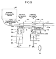
- a heat energy recovery apparatus according to a third embodiment of the present invention will be described with reference to FIG. 5.
- an exhaust heat recovery apparatus which recovers exhaust heat of an internal combustion engine 60 will be explained with an example.
- the exhaust heat recovery apparatus of the third embodiment in the exhaust heat recovery apparatus of the aforementioned second embodiment, includes a working gas supply path, which is generally parallel to a direction of the thermal expansion of the exhaust flow path 61, is provided on at least one portion of the working gas supply pipe 34 where tensile stress and/or compressive stress occur.
- extending means which is extensible in the same direction as that of the thermal expansion when the exhaust flow path 61 expands thermally, is provided on the working gas supply path; and, when compressive stress occurs in the working gas supply path, shrinking means, which is shrinkable in the same direction as that of the thermal expansion when the exhaust flow path 61 expands thermally, is provided on the working gas supply path.
- the third embodiment explains with an example that the exhaust flow path 61 of the internal combustion engine 60 expands thermally in a direction marked by an arrow B in FIG. 5 to generate tensile stress in working gas supply pipe 34 of the expander 30 in the direction marked by the arrow B. Therefore, in the third embodiment, as shown in FIG. 5, the expander 30 is disposed on the side of the exhaust flow path 61 of the internal combustion engine 60 than the heat exchanger 120 in the axis line direction thereof; and a working gas supply path 34a generally parallel to the direction of the thermal expansion (the arrow B) of the exhaust flow path 61 is provided in the working gas supply pipe 34. Then, a bellows 38, which is able to expand under pressure toward the direction of the arrow B as the compressed working gas flows in, is provided on the working gas supply path 34a as the extending means.
- the bellows 38 of the third embodiment is set so that an amount of extension of the exhaust flow path 61 of the internal combustion engine 60 toward the direction of the arrow B during the thermal expansion is previously determined by experiments or simulation and expansion under pressure is performed by an amount of extension capable of counterbalancing the amount of extension of the exhaust flow path 61 when the compressed working gas flows in.
- the compressed working gas flows into the bellows 38 to expand under pressure toward the same direction as in the case of the tensile stress of the working gas supply pipe 34, whereby the tensile stress of the working gas supply pipe 34, which occurs with the thermal expansion of the exhaust flow path 61 of the internal combustion engine 60, can be absorbed. Consequently, even when a relative position relationship between the exhaust flow path 61 of the internal combustion engine 60 and the expander 30 of the exhaust heat recovery apparatus and the working gas supply pipe 34 thereof is fixed, strains generated in the exhaust heat recovery apparatus, such as bends and torsions in the working gas supply pipe 34, connecting rod 33, and crankshaft 40 can be avoided and damages thereof can be avoided.
- the second interconnecting piping 120b of the heat exchanger 120 also expands thermally toward the direction of the arrow A, at that time, the bellows 18 provided in the working gas exhaust pipe 15 of the compressor 10 expands under pressure as the compressed working gas flows in, whereby strains generated in the exhaust heat recovery apparatus, such as bends and torsions in the working gas exhaust pipe 15, connecting rod 13, and crankshaft 40 of the compressor 10 side can be avoided and damages thereof can be avoided.
- extending means in the working gas supply pipe 34 to which pressure is applied in the same direction of the thermal expansion of the exhaust flow path 61 of the internal combustion engine 60 with the flowing-in of the working gas.
- extending means in the same direction as in the case of the thermal expansion; and therefore, tensile stress which occurs in the working gas supply pipe 34 can be relieved, whereby strains generated in the exhaust heat recovery apparatus can be suppressed and damages thereof can be avoided. That is, it can exhibit the same effects as in the case of the bellows 38 without actually extending as the aforementioned bellows 38.
- Such extending means is especially effective when there occurs a little thermal expansion in the exhaust flow path 61.
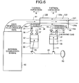
- a heat energy recovery apparatus according to a fourth embodiment of the present invention will be described with reference to FIG. 6.
- an exhaust heat recovery apparatus which recovers exhaust heat of an internal combustion engine 60 will be explained with an example.
- the heat energy recovery apparatus is suitable for technology which absorbs or relieves tensile stress or compressive stress applied to the heat energy recovery apparatus, the stresses being generated with the thermal expansion of the heat source, and suppresses strains thereof.
- a heat energy recovery apparatus includes a compressor (10); a heat exchanger (20; 120); an expander (30); a working gas exhaust pipe (15) which leads the working gas compressed by the compressor (10) to the heat exchanger (20; 120); a working gas exhaust path (15a) generally parallel to a direction of the thermal expansion of the heat exchanger (20; 120); an extending unit (18) extensible in the same direction as that of the thermal expansion when the heat exchanger (20; 120) expands thermally and tensile stress occurs in the working gas exhaust path (15a) with the thermal expansion of the heat exchanger (20; 120); and a shrinking unit (18) shrinkable in the same direction as that of the thermal expansion when the heat exchanger (20; 120) expands thermally and compressive stress occurs in the working gas exhaust path (15a) with the thermal expansion of the heat exchanger (20; 120).
Landscapes
- Engineering & Computer Science (AREA)
- Chemical & Material Sciences (AREA)
- Combustion & Propulsion (AREA)
- Mechanical Engineering (AREA)
- General Engineering & Computer Science (AREA)
- Engine Equipment That Uses Special Cycles (AREA)
Applications Claiming Priority (1)
| Application Number | Priority Date | Filing Date | Title |
|---|---|---|---|
| JP2005106311A JP2006283699A (ja) | 2005-04-01 | 2005-04-01 | 熱エネルギ回収装置 |
Publications (1)
| Publication Number | Publication Date |
|---|---|
| EP1754877A1 true EP1754877A1 (de) | 2007-02-21 |
Family
ID=37068709
Family Applications (1)
| Application Number | Title | Priority Date | Filing Date |
|---|---|---|---|
| EP06111106A Withdrawn EP1754877A1 (de) | 2005-04-01 | 2006-03-14 | Vorrichtung zur Rückgewinnung von Wärmeenergie |
Country Status (3)
| Country | Link |
|---|---|
| US (1) | US20060218919A1 (de) |
| EP (1) | EP1754877A1 (de) |
| JP (1) | JP2006283699A (de) |
Cited By (1)
| Publication number | Priority date | Publication date | Assignee | Title |
|---|---|---|---|---|
| US10852339B2 (en) | 2015-09-04 | 2020-12-01 | Dehn Se + Co Kg | Method for sensing lightning-current parameters at installations having one or more capturing devices and lightning-current diversion paths |
Families Citing this family (20)
| Publication number | Priority date | Publication date | Assignee | Title |
|---|---|---|---|---|
| US20080105125A1 (en) * | 2006-11-07 | 2008-05-08 | Lauson Robert G | Method and device for disposing of air compression system effluent |
| FR2914696A1 (fr) * | 2007-04-03 | 2008-10-10 | Etienne Baudino | Systeme hybride motorise |
| DE102007049522A1 (de) * | 2007-10-15 | 2009-04-16 | Rerum Cognitio Forschungszentrum Gmbh | Thermo-Hydraulisches Verfahren zur Druckerhöhung diverser Arbeitsfluids und deren Anwendung |
| EP2318781A1 (de) * | 2008-07-04 | 2011-05-11 | Heleos Technology Gmbh | Verfahren und vorrichtung zur übertragung von wärme von einem ersten medium auf ein zweites medium |
| EP2334602B1 (de) * | 2008-10-02 | 2014-12-10 | BAUDINO, Etienne | Hybridmotorsystem |
| DE102009015693A1 (de) * | 2009-03-31 | 2010-10-07 | Walter Hamberger | Fahrzeug mit einer Verbrennungskraftmaschine und einer deren Abwärme nutzenden Wärmekraftmaschine als Antriebe |
| DE102010000487B4 (de) * | 2010-02-21 | 2023-06-29 | von Görtz & Finger Techn. Entwicklungs GmbH | Verfahren und Vorrichtung für Verbrennungskraftmaschinen |
| CN102032832B (zh) * | 2010-10-22 | 2012-11-07 | 浙江大学 | 一种柔性换热件及其加工方法 |
| JP5533713B2 (ja) * | 2011-02-04 | 2014-06-25 | トヨタ自動車株式会社 | 排熱回収用スターリングエンジンの出力制御装置 |
| JP5874366B2 (ja) * | 2011-12-12 | 2016-03-02 | いすゞ自動車株式会社 | ディーゼルエンジンの動力発生方法及び動力発生システム |
| EP2794346B1 (de) | 2011-12-20 | 2017-03-22 | Carrier Corporation | Transportkühlsystem mit triebwerkswellen-pferdestärkenverstärkung |
| ITTO20120732A1 (it) * | 2012-08-16 | 2014-02-17 | Aldo Placidi | Scambiatore di calore per un gruppo di conversione di energia, e gruppo di conversione di energia provvisto di tale scambiatore di calore |
| EP2890886B1 (de) * | 2012-08-30 | 2020-04-08 | Enhanced Energy Group LLC | Hubkolben-brennkraftmaschinensystem |
| EP2923058A4 (de) | 2012-11-20 | 2016-09-14 | Dulob Ab | Heissgasmotor |
| CN103423020B (zh) * | 2013-08-08 | 2016-04-13 | 中国第一汽车股份有限公司 | 热量回收系统 |
| JP6507006B2 (ja) * | 2015-03-26 | 2019-04-24 | 月島機械株式会社 | 流動層焼却設備 |
| CN104806296A (zh) * | 2015-05-14 | 2015-07-29 | 戴跃东 | 热源式发动机 |
| US10844817B2 (en) * | 2018-04-23 | 2020-11-24 | Ford Global Technologies, Llc | Convolute-swirl integrated duct for swirl generation |
| BR102018015325A2 (pt) * | 2018-07-26 | 2020-02-04 | Finco Saulo | motor de combustão interna integrado formado por uma unidade principal a turbina e uma unidade secundária a pistões e processo de controle para o ciclo termodinâmico do motor. |
| BR102018015947A2 (pt) * | 2018-08-03 | 2020-02-27 | Saulo Finco | Motor de combustão interna integrado formado por uma unidade principal de ciclo diesel e uma unidade secundária a pistões e processo de controle para o ciclo termodinâmico do motor |
Citations (3)
| Publication number | Priority date | Publication date | Assignee | Title |
|---|---|---|---|---|
| GB127686A (en) | 1918-03-21 | 1919-05-21 | Frederick William Lanchester | Improvements in and relating to Hot Air Engines. |
| JPS56101045A (en) * | 1980-01-11 | 1981-08-13 | Mitsubishi Heavy Ind Ltd | Cooling system for internal combustion engine |
| US4389844A (en) * | 1981-06-11 | 1983-06-28 | Mechanical Technology Incorporated | Two stage stirling engine |
Family Cites Families (14)
| Publication number | Priority date | Publication date | Assignee | Title |
|---|---|---|---|---|
| US3894581A (en) * | 1973-04-16 | 1975-07-15 | Garrett Corp | Method of manifold construction for formed tube-sheet heat exchanger and structure formed thereby |
| US3968834A (en) * | 1975-02-07 | 1976-07-13 | Caterpillar Tractor Co. | Heat exchanger mounting for a turbine engine |
| US4008574A (en) * | 1975-10-20 | 1977-02-22 | Rein Charles R | Power plant with air working fluid |
| US4090358A (en) * | 1976-10-01 | 1978-05-23 | Caterpillar Tractor Co. | Heat exchanger support system |
| DE2758998C2 (de) * | 1977-12-30 | 1980-02-21 | Mtu Motoren- Und Turbinen-Union Muenchen Gmbh, 8000 Muenchen | Rekuperator fur den Wärmeaustausch zwischen zwei Strömungsmitteln unterschiedlicher Temperaturen |
| WO2000006876A1 (en) * | 1998-07-31 | 2000-02-10 | The Texas A & M University System | Quasi-isothermal brayton cycle engine |
| US6216462B1 (en) * | 1999-07-19 | 2001-04-17 | The United States Of America As Represented By The Administrator Of The Environmental Protection Agency | High efficiency, air bottoming engine |
| US6363737B1 (en) * | 2000-03-07 | 2002-04-02 | Robby D. Raney | Heat exchanger and method of use therefor |
| US7017656B2 (en) * | 2001-05-24 | 2006-03-28 | Honeywell International, Inc. | Heat exchanger with manifold tubes for stiffening and load bearing |
| DE10135303A1 (de) * | 2001-07-19 | 2003-02-13 | Bosch Gmbh Robert | Verfahren und Vorrichtung zur Abgasnachbehandlung in Verbrennungskraftmaschinen |
| US7036562B2 (en) * | 2002-02-26 | 2006-05-02 | Honeywell International, Inc. | Heat exchanger with core and support structure coupling for reduced thermal stress |
| AU2003261920A1 (en) * | 2002-09-06 | 2004-03-29 | Ork Corporation | Metal bellows tube, method of producing the same, and flexible tube for high-pressure fluid |
| US6672063B1 (en) * | 2002-09-25 | 2004-01-06 | Richard Alan Proeschel | Reciprocating hot air bottom cycle engine |
| JP4010238B2 (ja) * | 2002-12-06 | 2007-11-21 | 東海ゴム工業株式会社 | 蛇腹金属管付ホース |
-
2005
- 2005-04-01 JP JP2005106311A patent/JP2006283699A/ja active Pending
-
2006
- 2006-03-07 US US11/368,541 patent/US20060218919A1/en not_active Abandoned
- 2006-03-14 EP EP06111106A patent/EP1754877A1/de not_active Withdrawn
Patent Citations (3)
| Publication number | Priority date | Publication date | Assignee | Title |
|---|---|---|---|---|
| GB127686A (en) | 1918-03-21 | 1919-05-21 | Frederick William Lanchester | Improvements in and relating to Hot Air Engines. |
| JPS56101045A (en) * | 1980-01-11 | 1981-08-13 | Mitsubishi Heavy Ind Ltd | Cooling system for internal combustion engine |
| US4389844A (en) * | 1981-06-11 | 1983-06-28 | Mechanical Technology Incorporated | Two stage stirling engine |
Cited By (1)
| Publication number | Priority date | Publication date | Assignee | Title |
|---|---|---|---|---|
| US10852339B2 (en) | 2015-09-04 | 2020-12-01 | Dehn Se + Co Kg | Method for sensing lightning-current parameters at installations having one or more capturing devices and lightning-current diversion paths |
Also Published As
| Publication number | Publication date |
|---|---|
| US20060218919A1 (en) | 2006-10-05 |
| JP2006283699A (ja) | 2006-10-19 |
Similar Documents
| Publication | Publication Date | Title |
|---|---|---|
| US20060218919A1 (en) | Heat energy recovery apparatus | |
| CN105531456B (zh) | 内燃机操作方法以及完成该方法的内燃机 | |
| CN112576404B (zh) | 自由活塞和气缸组件以及斯特林发动机 | |
| RU2018108835A (ru) | Устройство термического сжатия газообразной текучей среды | |
| JP2011127870A (ja) | 熱音響機関 | |
| CN100487235C (zh) | 热机 | |
| KR20170067708A (ko) | 가요성 장치, 선형 회전 변환기 및 시스템 | |
| CN110462171B (zh) | 热力发动机 | |
| US20090277152A1 (en) | Quasi-isobaric heat engine | |
| US5088284A (en) | Compressor integral with Stirling engine | |
| US20100257857A1 (en) | Stirling engine | |
| JP2020529550A (ja) | 効率的熱回収エンジン | |
| US6474058B1 (en) | Warren cycle engine | |
| CN113047948B (zh) | 一种基于刚性连接的自由活塞发电机 | |
| Gupta et al. | Review of working of Stirling engines | |
| WO2005090771A1 (ja) | スターリング機関 | |
| CN101881264B (zh) | 一种线性压缩机用吸排气一体化吸排气装置 | |
| CN117029302A (zh) | 一种集成式同轴脉管制冷机 | |
| KR101714186B1 (ko) | 베인 로터형 스터링 엔진 | |
| US5134848A (en) | Stirling cycle apparatus | |
| JP5444288B2 (ja) | 燃料から機械的エネルギーを生み出すための燃焼装置および方法 | |
| US20100269502A1 (en) | External combustion engine | |
| US10221725B2 (en) | Strain augmented thermodynamic power cycle | |
| CN216077785U (zh) | 一种超薄气缸 | |
| JPWO2018181975A1 (ja) | 往復動式ブースター圧縮機 |
Legal Events
| Date | Code | Title | Description |
|---|---|---|---|
| PUAI | Public reference made under article 153(3) epc to a published international application that has entered the european phase |
Free format text: ORIGINAL CODE: 0009012 |
|
| 17P | Request for examination filed |
Effective date: 20060314 |
|
| AK | Designated contracting states |
Kind code of ref document: A1 Designated state(s): AT BE BG CH CY CZ DE DK EE ES FI FR GB GR HU IE IS IT LI LT LU LV MC NL PL PT RO SE SI SK TR |
|
| AX | Request for extension of the european patent |
Extension state: AL BA HR MK YU |
|
| AKX | Designation fees paid |
Designated state(s): DE FR |
|
| 17Q | First examination report despatched |
Effective date: 20071213 |
|
| STAA | Information on the status of an ep patent application or granted ep patent |
Free format text: STATUS: THE APPLICATION IS DEEMED TO BE WITHDRAWN |
|
| 18D | Application deemed to be withdrawn |
Effective date: 20100202 |