EP1754879B1 - Abgasrückführsystem - Google Patents
Abgasrückführsystem Download PDFInfo
- Publication number
- EP1754879B1 EP1754879B1 EP06117454A EP06117454A EP1754879B1 EP 1754879 B1 EP1754879 B1 EP 1754879B1 EP 06117454 A EP06117454 A EP 06117454A EP 06117454 A EP06117454 A EP 06117454A EP 1754879 B1 EP1754879 B1 EP 1754879B1
- Authority
- EP
- European Patent Office
- Prior art keywords
- egr
- air
- exhaust
- compressor
- cooler
- Prior art date
- Legal status (The legal status is an assumption and is not a legal conclusion. Google has not performed a legal analysis and makes no representation as to the accuracy of the status listed.)
- Ceased
Links
- 238000001816 cooling Methods 0.000 claims description 14
- 238000002485 combustion reaction Methods 0.000 claims description 8
- 238000011144 upstream manufacturing Methods 0.000 claims description 4
- 239000007789 gas Substances 0.000 description 13
- 239000000498 cooling water Substances 0.000 description 1
- 238000010586 diagram Methods 0.000 description 1
Images
Classifications
-
- F—MECHANICAL ENGINEERING; LIGHTING; HEATING; WEAPONS; BLASTING
- F02—COMBUSTION ENGINES; HOT-GAS OR COMBUSTION-PRODUCT ENGINE PLANTS
- F02B—INTERNAL-COMBUSTION PISTON ENGINES; COMBUSTION ENGINES IN GENERAL
- F02B29/00—Engines characterised by provision for charging or scavenging not provided for in groups F02B25/00, F02B27/00 or F02B33/00 - F02B39/00; Details thereof
- F02B29/04—Cooling of air intake supply
- F02B29/0406—Layout of the intake air cooling or coolant circuit
- F02B29/0425—Air cooled heat exchangers
-
- F—MECHANICAL ENGINEERING; LIGHTING; HEATING; WEAPONS; BLASTING
- F02—COMBUSTION ENGINES; HOT-GAS OR COMBUSTION-PRODUCT ENGINE PLANTS
- F02M—SUPPLYING COMBUSTION ENGINES IN GENERAL WITH COMBUSTIBLE MIXTURES OR CONSTITUENTS THEREOF
- F02M26/00—Engine-pertinent apparatus for adding exhaust gases to combustion-air, main fuel or fuel-air mixture, e.g. by exhaust gas recirculation [EGR] systems
- F02M26/02—EGR systems specially adapted for supercharged engines
- F02M26/04—EGR systems specially adapted for supercharged engines with a single turbocharger
- F02M26/05—High pressure loops, i.e. wherein recirculated exhaust gas is taken out from the exhaust system upstream of the turbine and reintroduced into the intake system downstream of the compressor
-
- F—MECHANICAL ENGINEERING; LIGHTING; HEATING; WEAPONS; BLASTING
- F02—COMBUSTION ENGINES; HOT-GAS OR COMBUSTION-PRODUCT ENGINE PLANTS
- F02M—SUPPLYING COMBUSTION ENGINES IN GENERAL WITH COMBUSTIBLE MIXTURES OR CONSTITUENTS THEREOF
- F02M26/00—Engine-pertinent apparatus for adding exhaust gases to combustion-air, main fuel or fuel-air mixture, e.g. by exhaust gas recirculation [EGR] systems
- F02M26/02—EGR systems specially adapted for supercharged engines
- F02M26/09—Constructional details, e.g. structural combinations of EGR systems and supercharger systems; Arrangement of the EGR and supercharger systems with respect to the engine
- F02M26/10—Constructional details, e.g. structural combinations of EGR systems and supercharger systems; Arrangement of the EGR and supercharger systems with respect to the engine having means to increase the pressure difference between the exhaust and intake system, e.g. venturis, variable geometry turbines, check valves using pressure pulsations or throttles in the air intake or exhaust system
-
- F—MECHANICAL ENGINEERING; LIGHTING; HEATING; WEAPONS; BLASTING
- F02—COMBUSTION ENGINES; HOT-GAS OR COMBUSTION-PRODUCT ENGINE PLANTS
- F02M—SUPPLYING COMBUSTION ENGINES IN GENERAL WITH COMBUSTIBLE MIXTURES OR CONSTITUENTS THEREOF
- F02M26/00—Engine-pertinent apparatus for adding exhaust gases to combustion-air, main fuel or fuel-air mixture, e.g. by exhaust gas recirculation [EGR] systems
- F02M26/13—Arrangement or layout of EGR passages, e.g. in relation to specific engine parts or for incorporation of accessories
- F02M26/22—Arrangement or layout of EGR passages, e.g. in relation to specific engine parts or for incorporation of accessories with coolers in the recirculation passage
- F02M26/23—Layout, e.g. schematics
- F02M26/27—Layout, e.g. schematics with air-cooled heat exchangers
-
- F—MECHANICAL ENGINEERING; LIGHTING; HEATING; WEAPONS; BLASTING
- F02—COMBUSTION ENGINES; HOT-GAS OR COMBUSTION-PRODUCT ENGINE PLANTS
- F02M—SUPPLYING COMBUSTION ENGINES IN GENERAL WITH COMBUSTIBLE MIXTURES OR CONSTITUENTS THEREOF
- F02M26/00—Engine-pertinent apparatus for adding exhaust gases to combustion-air, main fuel or fuel-air mixture, e.g. by exhaust gas recirculation [EGR] systems
- F02M26/13—Arrangement or layout of EGR passages, e.g. in relation to specific engine parts or for incorporation of accessories
- F02M26/17—Arrangement or layout of EGR passages, e.g. in relation to specific engine parts or for incorporation of accessories in relation to the intake system
- F02M26/19—Means for improving the mixing of air and recirculated exhaust gases, e.g. venturis or multiple openings to the intake system
-
- Y—GENERAL TAGGING OF NEW TECHNOLOGICAL DEVELOPMENTS; GENERAL TAGGING OF CROSS-SECTIONAL TECHNOLOGIES SPANNING OVER SEVERAL SECTIONS OF THE IPC; TECHNICAL SUBJECTS COVERED BY FORMER USPC CROSS-REFERENCE ART COLLECTIONS [XRACs] AND DIGESTS
- Y02—TECHNOLOGIES OR APPLICATIONS FOR MITIGATION OR ADAPTATION AGAINST CLIMATE CHANGE
- Y02T—CLIMATE CHANGE MITIGATION TECHNOLOGIES RELATED TO TRANSPORTATION
- Y02T10/00—Road transport of goods or passengers
- Y02T10/10—Internal combustion engine [ICE] based vehicles
- Y02T10/12—Improving ICE efficiencies
Definitions
- the present invention relates to an exhaust gas recirculation system for an internal combustion engine having a combustion air intake circuit, an exhaust circuit for communicating engine exhaust to the environment, the EGR system comprising an air-to-gas EGR cooler, an air inlet line communicating cooling inlet air to the EGR cooler, an EGR supply line communicating exhaust from the exhaust circuit to the EGR cooler.
- EGR exhaust gas re-circulation
- US-B1-6,216,458 shows an exhaust gas recirculation system for a turbo-charged internal combustion engine.
- the system includes a recirculation conduit for recirculation a volume of exhaust gas from the exhaust manifold to the intake manifold; a cooling air conduit for transporting a flow of cooling air; and a gas-to-air heat exchanger disposed in operative association with the recirculation conduit and the cooling air conduit and adapted for cooling the volume of recirculated exhaust gas in the recirculation conduit.
- an object of this invention is to provide an engine EGR system which cools the EGR without increasing the temperature of the engine.
- an exhaust gas recirculation (EGR) system for an internal combustion engine having a combustion air intake circuit and an exhaust circuit for communicating engine exhaust to the environment.
- the EGR system includes an air-to-gas EGR cooler, an air inlet line communicating cooling inlet air to the EGR cooler, an EGR supply line communicating exhaust from the exhaust circuit to the EGR cooler, a venturi unit in the exhaust circuit, and an air outlet line communicating heated air from the EGR cooler to the venturi unit. Flow of exhaust through the venturi creates a pressure which draws cooling air through the EGR cooler.
- the EGR system also includes a turbocharger unit having an exhaust turbine and an inlet air compressor.
- a compressor outlet circuit communicates air from the compressor to an air intake of the engine.
- a valve is located in the compressor outlet circuit.
- An EGR venturi is in the compressor outlet circuit and is connected in parallel with the valve.
- a cooled EGR line communicates cooled exhaust gas from the EGR cooler to a suction port of the EGR venturi.
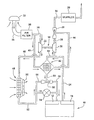
- an engine 10 includes a combustion air intake 12, an exhaust outlet 14 and a conventional turbo-compressor 18 which includes a turbine 20 and a compressor 22.
- An exhaust line 24 communicates engine exhaust from exhaust outlet 14 to the turbine 20.
- Exhaust line 26 communicates exhaust from turbine 20 to an exhaust venturi 28.
- Exhaust outlet line 30 communicates exhaust from venturi 28 to the environment through a muffler 29.
- An air intake 32 and line 34 provides intake air to air filter 36.
- Main intake air line 38 communicates air to the compressor 22.
- Air line 40 communicates a portion (preferably 10%) of intake air to an air inlet of an EGR cooler 42.
- Line 44 communicates cooling air from EGR cooler 42 to an suction port in the venturi 28.
- Line 46 communicates intake air from compressor 22 to a charge air cooler 48, which is cooled by air blown by fan 50.
- Line 52 communicates cooled charge air from charge air cooler 48 to the engine air intake 12 via a control valve 54.
- Branch line 56 communicates line 52 to an inlet of an EGR venturi 58.
- Branch line 60 communicates an outlet of EGR venturi 58 back to line 52 on the other side of valve 54.
- An EGR line 62 communicates a portion of the exhaust from exhaust line 24 to an inlet of EGR cooler 42.
- the EGR line 62 is communicated with the exhaust circuit upstream of the venturi 28 and upstream of the turbine 20.
- Line 64 communicates cooled EGR from EGR cooler 42 to a suction port of venturi 58.
- the charge air cooler there is a second air-to-air type cooler to cool the hot recirculated exhaust gases.
- the EGR cooler can be small due to the large temperature difference between the hot exhaust gas and the cooling air, and the EGR is cooled without increasing the size of the radiator.
Landscapes
- Engineering & Computer Science (AREA)
- Chemical & Material Sciences (AREA)
- Combustion & Propulsion (AREA)
- Mechanical Engineering (AREA)
- General Engineering & Computer Science (AREA)
- Physics & Mathematics (AREA)
- Thermal Sciences (AREA)
- Exhaust-Gas Circulating Devices (AREA)
- Supercharger (AREA)
Claims (8)
- Abgasrückführungssystem (AGR-System) für einen Verbrennungsmotor (10) mit einem Verbrennungslufteinlasskreis und einem Abgaskreis zur Weiterleitung von Motorabgas an die Umgebung, wobei das AGR-System einen Luft-Gas-AGR-Kühler (42), eine Lufteinlassleitung (34), die Kühleinlassluft an den AGR-Kühler (42) weiterleitet und eine AGR-Versorgungsleitung (52), die Abgas von dem Abgaskreis an den AGR-Kühler (42) weiterleitet, aufweist, dadurch gekennzeichnet, dass eine Venturi-Einheit (28) in dem Abgaskreis vorgesehen ist und dass eine Luftauslassleitung (44) erwärmte Luft aus dem AGR-Kühler (42) an die Venturi-Einheit (28) weiterleitet, wobei der Abgasstrom durch das Venturi (28) einen Druck erzeugt, der Kühlluft durch den AGR-Kühler (42) saugt.
- AGR-System nach Anspruch 1, gekennzeichnet durch eine Turboladereinheit (18) mit einer Abgasturbine (20) und einem Einlassluftkompressor (22), einen Kompressorauslasskreis, der Luft von dem Kompressor (22) an einen Lufteinlass (12) des Motors (10) weiterleitet, ein Ventil (54) in dem Kompressorauslasskreis, ein AGR-Venturi (58) im Kompressorauslasskreis, das parallel zu dem Ventil (54) geschaltet ist, und eine gekühlte AGR-Leitung (64), die gekühltes Abgas von dem AGR-Kühler (42) an eine Saugöffnung des AGR-Venturis (58) weiterleitet.
- AGR-System nach Anspruch 2, gekennzeichnet durch einen Ladeluftkühler (48), der einen Druckluft von dem Kompressor (22) empfangenden Einlass und einen gekühlte Ladeluft an das AGR-Venturi (58) und an das Ventil (54) weiterleitenden Auslass aufweist.
- AGR-System nach Anspruch 2, dadurch gekennzeichnet, dass die AGR-Leitung (64) mit dem Abgaskreis stromaufwärts des Venturis (28) in Verbindung steht.
- AGR-System nach einem oder mehreren der Ansprüche 2 bis 4, dadurch gekennzeichnet, dass die AGR-Leitung (64) mit dem Abgaskreis stromaufwärts des Turbokompressors (22) verbunden ist.
- AGR-System nach einem oder mehreren der vorhergehenden Ansprüche, gekennzeichnet durch einen Einlassluftfilter, wobei die Lufteinlassleitung gekühlte Einlassluft von dem Luftfilter (36) an den AGR-Kühler (42) weiterleitet.
- AGR-System nach einem oder mehreren der vorhergehenden Ansprüche, gekennzeichnet durch ein Ventil (54) zur Steuerung des AGR-Stroms durch den AGR-Kühler (42) .
- AGR-System nach Anspruch 1, gekennzeichnet durch eine Turboladereinheit (18) mit einer Abgasturbine (20) und einem Einlassluftkompressor (22), und einen Ladeluftkühler (48) zwischen dem Kompressor (22) und einem Motorlufteinlass (12).
Applications Claiming Priority (1)
| Application Number | Priority Date | Filing Date | Title |
|---|---|---|---|
| US11/207,291 US7322192B2 (en) | 2005-08-19 | 2005-08-19 | Exhaust gas recirculation system |
Publications (2)
| Publication Number | Publication Date |
|---|---|
| EP1754879A1 EP1754879A1 (de) | 2007-02-21 |
| EP1754879B1 true EP1754879B1 (de) | 2009-04-29 |
Family
ID=37459506
Family Applications (1)
| Application Number | Title | Priority Date | Filing Date |
|---|---|---|---|
| EP06117454A Ceased EP1754879B1 (de) | 2005-08-19 | 2006-07-19 | Abgasrückführsystem |
Country Status (4)
| Country | Link |
|---|---|
| US (1) | US7322192B2 (de) |
| EP (1) | EP1754879B1 (de) |
| JP (1) | JP2007051638A (de) |
| DE (1) | DE602006006509D1 (de) |
Families Citing this family (26)
| Publication number | Priority date | Publication date | Assignee | Title |
|---|---|---|---|---|
| US7549412B2 (en) * | 1999-12-17 | 2009-06-23 | Satnarine Singh | System and method for recovering wasted energy from an internal combustion engine |
| DE102005002518B3 (de) * | 2005-01-19 | 2006-08-03 | Pierburg Gmbh | Abgasrückführungssystem für eine Brennkraftmaschine sowie Abgasrückführungsverfahren |
| FR2892155B1 (fr) * | 2005-10-19 | 2007-12-14 | Inst Francais Du Petrole | Circuit d'alimentation en au moins un fluide d'un moteur suralimente et procede pour alimenter en au moins un fluide un tel moteur |
| US7448368B2 (en) * | 2006-11-17 | 2008-11-11 | Gm Global Technology Operations, Inc. | Exhaust gas recirculation system for an internal combustion engine |
| US7584748B2 (en) * | 2006-11-20 | 2009-09-08 | Gm Global Technology Operations, Inc. | Exhaust gas recirculation system for an internal combustion engine |
| DE102007051659A1 (de) * | 2007-10-26 | 2009-04-30 | Behr Gmbh & Co. Kg | Vorrichtung und Verfahren zur Rückführung von Abgas eines Verbrennungsmotors |
| DE102007054227A1 (de) * | 2007-11-12 | 2009-05-14 | Man Nutzfahrzeuge Ag | Brennkraftmaschine mit AGR-Kühler |
| US7757678B2 (en) * | 2008-05-07 | 2010-07-20 | General Electric Company | Locomotive exhaust gas recirculation cooling |
| US8448626B2 (en) * | 2008-08-13 | 2013-05-28 | International Engine Intellectual Property Company, Llc | Exhaust system for engine braking |
| SE533123C2 (sv) * | 2008-12-08 | 2010-06-29 | Scania Cv Ab | Arrangemang för kylning av återcirkulerande avgaser hos en förbränningsmotor |
| SE533508C2 (sv) * | 2009-03-13 | 2010-10-12 | Scania Cv Ab | Arrangemang för kylning av återcirkulerande avgaser hos en förbränningsmotor |
| US8353275B2 (en) * | 2010-01-08 | 2013-01-15 | Ford Global Technologies, Llc | Dual throttle for improved tip-out stability in boosted engine system |
| US8091359B2 (en) | 2010-06-03 | 2012-01-10 | Ford Global Technologies, Llc | Exhaust heat recovery for engine heating and exhaust cooling |
| US8746217B2 (en) | 2011-10-07 | 2014-06-10 | Deere & Company | Power system comprising an air cooled HT EGR cooler and LT EGR cooler |
| US9151250B2 (en) | 2012-04-05 | 2015-10-06 | Donald B. Scoggins | Fluid cooling system |
| US9291097B2 (en) | 2013-06-04 | 2016-03-22 | Caterpillar Inc. | Cooling module for electronic engine components |
| CN104074636B (zh) * | 2013-12-23 | 2016-05-04 | 哈尔滨工程大学 | 具有加湿效果的柴油机egr系统 |
| US20170218890A1 (en) * | 2014-09-29 | 2017-08-03 | Boost Mechanics (Pty) Limited | A turbomachinery assembly for an internal combustion engine using a venturi apparatus |
| US10316803B2 (en) | 2017-09-25 | 2019-06-11 | Woodward, Inc. | Passive pumping for recirculating exhaust gas |
| CN108757155B (zh) * | 2018-06-27 | 2020-01-14 | 福州大学 | 一种基于文丘里管的涡轮增压系统及其工作方法 |
| US10995705B2 (en) | 2019-02-07 | 2021-05-04 | Woodward, Inc. | Modular exhaust gas recirculation system |
| US11499508B2 (en) | 2019-08-14 | 2022-11-15 | Transportation Ip Holdings, Llc | Cleaning system for an engine exhaust cooler |
| CN213175878U (zh) | 2020-01-08 | 2021-05-11 | 伍德沃德有限公司 | 排气气体再循环混合器和发动机系统 |
| US11215132B1 (en) | 2020-12-15 | 2022-01-04 | Woodward, Inc. | Controlling an internal combustion engine system |
| US11174809B1 (en) | 2020-12-15 | 2021-11-16 | Woodward, Inc. | Controlling an internal combustion engine system |
| US12270362B1 (en) | 2024-02-29 | 2025-04-08 | Fca Us Llc | System for selective liquid cooling of an air intake duct |
Family Cites Families (12)
| Publication number | Priority date | Publication date | Assignee | Title |
|---|---|---|---|---|
| US4094284A (en) * | 1975-10-21 | 1978-06-13 | Eltra Corporation | Emission control system |
| JPH0828253A (ja) * | 1994-07-15 | 1996-01-30 | Toyota Motor Corp | 内燃機関の2次空気供給装置 |
| US6216458B1 (en) * | 1997-03-31 | 2001-04-17 | Caterpillar Inc. | Exhaust gas recirculation system |
| US6003315A (en) * | 1997-03-31 | 1999-12-21 | Caterpillar Inc. | Exhaust gas recirculation system for an internal combustion engine |
| US6205775B1 (en) * | 1999-03-22 | 2001-03-27 | Caterpillar Inc. | Exhaust gas recirculation control system |
| JP4323680B2 (ja) * | 1999-09-30 | 2009-09-02 | 株式会社小松製作所 | 内燃機関の排気再循環制御装置 |
| JP2001342911A (ja) * | 2000-05-31 | 2001-12-14 | Komatsu Ltd | 内燃機関の排気再循環制御装置 |
| US6543428B1 (en) * | 2000-06-14 | 2003-04-08 | Caterpillar Inc. | Intake air separation system for an internal combustion engine |
| US6453893B1 (en) * | 2000-06-14 | 2002-09-24 | Caterpillar Inc | Intake air separation system for an internal combustion engine |
| JP2002221103A (ja) * | 2001-01-24 | 2002-08-09 | Komatsu Ltd | 排気再循環装置付き内燃機関システム |
| US6609374B2 (en) * | 2001-12-19 | 2003-08-26 | Caterpillar Inc | Bypass venturi assembly for an exhaust gas recirculation system |
| US7356987B2 (en) * | 2004-07-30 | 2008-04-15 | Caterpillar Inc. | Exhaust gas recirculation system having an electrostatic precipitator |
-
2005
- 2005-08-19 US US11/207,291 patent/US7322192B2/en not_active Expired - Fee Related
-
2006
- 2006-07-19 DE DE602006006509T patent/DE602006006509D1/de active Active
- 2006-07-19 EP EP06117454A patent/EP1754879B1/de not_active Ceased
- 2006-07-28 JP JP2006205501A patent/JP2007051638A/ja active Pending
Also Published As
| Publication number | Publication date |
|---|---|
| US20070039321A1 (en) | 2007-02-22 |
| US7322192B2 (en) | 2008-01-29 |
| DE602006006509D1 (de) | 2009-06-10 |
| EP1754879A1 (de) | 2007-02-21 |
| JP2007051638A (ja) | 2007-03-01 |
Similar Documents
| Publication | Publication Date | Title |
|---|---|---|
| EP1754879B1 (de) | Abgasrückführsystem | |
| US7254947B2 (en) | Vehicle cooling system | |
| US8453447B2 (en) | Two-stage exhaust gas turbocharging arrangement for an internal combustion engine | |
| US7322193B2 (en) | Exhaust gas recirculation system | |
| RU2589556C2 (ru) | Система двигателя и способ снижения стоимости ее производства | |
| EP2357351B1 (de) | Abgasrückführungssystem (EGR) und Energiesystem | |
| US8028523B2 (en) | Arrangement for recirculation of exhaust gases of a supercharged internal combustion engine | |
| JP2009511797A (ja) | 内燃機関の排ガスを再循環および冷却するための装置 | |
| JP4571673B2 (ja) | 車輌の冷却装置 | |
| US8201405B2 (en) | Crossover exhaust duct with front inside passage and rear outside passage | |
| EP1886012B1 (de) | Anordnung zur rückführung von abgasen einer aufgeladenen brennkraftmaschine | |
| CN111894769A (zh) | 发动机系统 | |
| ATE483906T1 (de) | Ein abgasrückführungssystem umfassender verbrennungsmotor | |
| US7584748B2 (en) | Exhaust gas recirculation system for an internal combustion engine | |
| US7448368B2 (en) | Exhaust gas recirculation system for an internal combustion engine | |
| JP2003278608A (ja) | Egr装置 | |
| CN215213736U (zh) | 一种发动机低压egr控制系统及车辆 | |
| CN206816354U (zh) | 一种增压发动机系统 | |
| US11261767B2 (en) | Bifurcated air induction system for turbocharged engines | |
| WO2009059923A3 (de) | Brennkraftmaschine mit einem einlasssystem und einem auslasssystem | |
| KR20220104441A (ko) | 라디에이터-인터쿨러 통합모듈 및 이를 포함하는 차량 | |
| GB2530509A (en) | A motor vehicle having a charge air cooler | |
| CN101988424B (zh) | 具有空气/水中间冷却器的火花点火式内燃机的节流 | |
| JP7135402B2 (ja) | 冷却システム | |
| CN121828038A (zh) | 车辆驱动机构、车辆、控制方法、存储介质及电子设备 |
Legal Events
| Date | Code | Title | Description |
|---|---|---|---|
| PUAI | Public reference made under article 153(3) epc to a published international application that has entered the european phase |
Free format text: ORIGINAL CODE: 0009012 |
|
| AK | Designated contracting states |
Kind code of ref document: A1 Designated state(s): AT BE BG CH CY CZ DE DK EE ES FI FR GB GR HU IE IS IT LI LT LU LV MC NL PL PT RO SE SI SK TR |
|
| AX | Request for extension of the european patent |
Extension state: AL BA HR MK YU |
|
| 17P | Request for examination filed |
Effective date: 20070821 |
|
| 17Q | First examination report despatched |
Effective date: 20070920 |
|
| AKX | Designation fees paid |
Designated state(s): DE GB |
|
| GRAP | Despatch of communication of intention to grant a patent |
Free format text: ORIGINAL CODE: EPIDOSNIGR1 |
|
| GRAS | Grant fee paid |
Free format text: ORIGINAL CODE: EPIDOSNIGR3 |
|
| GRAA | (expected) grant |
Free format text: ORIGINAL CODE: 0009210 |
|
| AK | Designated contracting states |
Kind code of ref document: B1 Designated state(s): DE GB |
|
| REG | Reference to a national code |
Ref country code: GB Ref legal event code: FG4D |
|
| REF | Corresponds to: |
Ref document number: 602006006509 Country of ref document: DE Date of ref document: 20090610 Kind code of ref document: P |
|
| PLBE | No opposition filed within time limit |
Free format text: ORIGINAL CODE: 0009261 |
|
| STAA | Information on the status of an ep patent application or granted ep patent |
Free format text: STATUS: NO OPPOSITION FILED WITHIN TIME LIMIT |
|
| 26N | No opposition filed |
Effective date: 20100201 |
|
| GBPC | Gb: european patent ceased through non-payment of renewal fee |
Effective date: 20100719 |
|
| PG25 | Lapsed in a contracting state [announced via postgrant information from national office to epo] |
Ref country code: GB Free format text: LAPSE BECAUSE OF NON-PAYMENT OF DUE FEES Effective date: 20100719 |
|
| PGFP | Annual fee paid to national office [announced via postgrant information from national office to epo] |
Ref country code: DE Payment date: 20200619 Year of fee payment: 15 |
|
| REG | Reference to a national code |
Ref country code: DE Ref legal event code: R119 Ref document number: 602006006509 Country of ref document: DE |
|
| PG25 | Lapsed in a contracting state [announced via postgrant information from national office to epo] |
Ref country code: DE Free format text: LAPSE BECAUSE OF NON-PAYMENT OF DUE FEES Effective date: 20220201 |