EP1754880A1 - Abgasrückführsystem - Google Patents
Abgasrückführsystem Download PDFInfo
- Publication number
- EP1754880A1 EP1754880A1 EP06117456A EP06117456A EP1754880A1 EP 1754880 A1 EP1754880 A1 EP 1754880A1 EP 06117456 A EP06117456 A EP 06117456A EP 06117456 A EP06117456 A EP 06117456A EP 1754880 A1 EP1754880 A1 EP 1754880A1
- Authority
- EP
- European Patent Office
- Prior art keywords
- egr
- air
- exhaust
- cooler
- communicating
- Prior art date
- Legal status (The legal status is an assumption and is not a legal conclusion. Google has not performed a legal analysis and makes no representation as to the accuracy of the status listed.)
- Withdrawn
Links
- 238000001816 cooling Methods 0.000 claims abstract description 15
- 238000002485 combustion reaction Methods 0.000 claims abstract description 12
- 239000003570 air Substances 0.000 claims description 70
- 239000000203 mixture Substances 0.000 claims description 8
- 239000012080 ambient air Substances 0.000 claims description 6
- 238000011144 upstream manufacturing Methods 0.000 claims description 3
- 238000009833 condensation Methods 0.000 description 4
- 230000005494 condensation Effects 0.000 description 4
- XLYOFNOQVPJJNP-UHFFFAOYSA-N water Substances O XLYOFNOQVPJJNP-UHFFFAOYSA-N 0.000 description 3
- LYCAIKOWRPUZTN-UHFFFAOYSA-N Ethylene glycol Chemical compound OCCO LYCAIKOWRPUZTN-UHFFFAOYSA-N 0.000 description 2
- 238000013459 approach Methods 0.000 description 2
- 230000007423 decrease Effects 0.000 description 2
- 238000010586 diagram Methods 0.000 description 2
- 230000000694 effects Effects 0.000 description 2
- 238000012986 modification Methods 0.000 description 2
- 230000004048 modification Effects 0.000 description 2
- 229910000881 Cu alloy Inorganic materials 0.000 description 1
- GRYLNZFGIOXLOG-UHFFFAOYSA-N Nitric acid Chemical class O[N+]([O-])=O GRYLNZFGIOXLOG-UHFFFAOYSA-N 0.000 description 1
- XSQUKJJJFZCRTK-UHFFFAOYSA-N Urea Chemical compound NC(N)=O XSQUKJJJFZCRTK-UHFFFAOYSA-N 0.000 description 1
- XAGFODPZIPBFFR-UHFFFAOYSA-N aluminium Chemical compound [Al] XAGFODPZIPBFFR-UHFFFAOYSA-N 0.000 description 1
- 229910052782 aluminium Inorganic materials 0.000 description 1
- 239000004202 carbamide Substances 0.000 description 1
- 239000003054 catalyst Substances 0.000 description 1
- 230000003197 catalytic effect Effects 0.000 description 1
- 239000003638 chemical reducing agent Substances 0.000 description 1
- 230000003247 decreasing effect Effects 0.000 description 1
- WGCNASOHLSPBMP-UHFFFAOYSA-N hydroxyacetaldehyde Natural products OCC=O WGCNASOHLSPBMP-UHFFFAOYSA-N 0.000 description 1
- 239000007788 liquid Substances 0.000 description 1
- 238000000034 method Methods 0.000 description 1
- 230000003647 oxidation Effects 0.000 description 1
- 238000007254 oxidation reaction Methods 0.000 description 1
Images

Classifications
-
- F—MECHANICAL ENGINEERING; LIGHTING; HEATING; WEAPONS; BLASTING
- F02—COMBUSTION ENGINES; HOT-GAS OR COMBUSTION-PRODUCT ENGINE PLANTS
- F02B—INTERNAL-COMBUSTION PISTON ENGINES; COMBUSTION ENGINES IN GENERAL
- F02B29/00—Engines characterised by provision for charging or scavenging not provided for in groups F02B25/00, F02B27/00 or F02B33/00 - F02B39/00; Details thereof
- F02B29/04—Cooling of air intake supply
- F02B29/0406—Layout of the intake air cooling or coolant circuit
- F02B29/0425—Air cooled heat exchangers
-
- F—MECHANICAL ENGINEERING; LIGHTING; HEATING; WEAPONS; BLASTING
- F02—COMBUSTION ENGINES; HOT-GAS OR COMBUSTION-PRODUCT ENGINE PLANTS
- F02M—SUPPLYING COMBUSTION ENGINES IN GENERAL WITH COMBUSTIBLE MIXTURES OR CONSTITUENTS THEREOF
- F02M26/00—Engine-pertinent apparatus for adding exhaust gases to combustion-air, main fuel or fuel-air mixture, e.g. by exhaust gas recirculation [EGR] systems
- F02M26/02—EGR systems specially adapted for supercharged engines
- F02M26/04—EGR systems specially adapted for supercharged engines with a single turbocharger
- F02M26/06—Low pressure loops, i.e. wherein recirculated exhaust gas is taken out from the exhaust downstream of the turbocharger turbine and reintroduced into the intake system upstream of the compressor
-
- F—MECHANICAL ENGINEERING; LIGHTING; HEATING; WEAPONS; BLASTING
- F02—COMBUSTION ENGINES; HOT-GAS OR COMBUSTION-PRODUCT ENGINE PLANTS
- F02M—SUPPLYING COMBUSTION ENGINES IN GENERAL WITH COMBUSTIBLE MIXTURES OR CONSTITUENTS THEREOF
- F02M26/00—Engine-pertinent apparatus for adding exhaust gases to combustion-air, main fuel or fuel-air mixture, e.g. by exhaust gas recirculation [EGR] systems
- F02M26/13—Arrangement or layout of EGR passages, e.g. in relation to specific engine parts or for incorporation of accessories
- F02M26/14—Arrangement or layout of EGR passages, e.g. in relation to specific engine parts or for incorporation of accessories in relation to the exhaust system
- F02M26/15—Arrangement or layout of EGR passages, e.g. in relation to specific engine parts or for incorporation of accessories in relation to the exhaust system in relation to engine exhaust purifying apparatus
-
- F—MECHANICAL ENGINEERING; LIGHTING; HEATING; WEAPONS; BLASTING
- F02—COMBUSTION ENGINES; HOT-GAS OR COMBUSTION-PRODUCT ENGINE PLANTS
- F02M—SUPPLYING COMBUSTION ENGINES IN GENERAL WITH COMBUSTIBLE MIXTURES OR CONSTITUENTS THEREOF
- F02M26/00—Engine-pertinent apparatus for adding exhaust gases to combustion-air, main fuel or fuel-air mixture, e.g. by exhaust gas recirculation [EGR] systems
- F02M26/13—Arrangement or layout of EGR passages, e.g. in relation to specific engine parts or for incorporation of accessories
- F02M26/22—Arrangement or layout of EGR passages, e.g. in relation to specific engine parts or for incorporation of accessories with coolers in the recirculation passage
- F02M26/23—Layout, e.g. schematics
- F02M26/27—Layout, e.g. schematics with air-cooled heat exchangers
-
- Y—GENERAL TAGGING OF NEW TECHNOLOGICAL DEVELOPMENTS; GENERAL TAGGING OF CROSS-SECTIONAL TECHNOLOGIES SPANNING OVER SEVERAL SECTIONS OF THE IPC; TECHNICAL SUBJECTS COVERED BY FORMER USPC CROSS-REFERENCE ART COLLECTIONS [XRACs] AND DIGESTS
- Y02—TECHNOLOGIES OR APPLICATIONS FOR MITIGATION OR ADAPTATION AGAINST CLIMATE CHANGE
- Y02T—CLIMATE CHANGE MITIGATION TECHNOLOGIES RELATED TO TRANSPORTATION
- Y02T10/00—Road transport of goods or passengers
- Y02T10/10—Internal combustion engine [ICE] based vehicles
- Y02T10/12—Improving ICE efficiencies
Definitions
- the present invention relates to an exhaust gas recirculation system for an internal combustion engine having a combustion air intake circuit, an exhaust manifold, and an exhaust circuit for communicating engine exhaust to the environment, the EGR system comprising an air-to-gas EGR cooler; an air supply conduit for supplying inlet air to the EGR cooler; an EGR supply conduit for communicating exhaust from the exhaust circuit to the EGR cooler; an EGR outlet conduit communicating cooled EGR from the EGR cooler to the intake circuit.
- EGR exhaust gas re-circulation
- EGR exhaust gas recirculation
- U.S. Patent No. 6,216,458 shows an EGR system with a gas to air EGR cooler and a valve in an air line between the EGR cooler and exhaust gas outlet.
- this patent describes embodiments which require pressurized cooling air from the intake air compressor, and a mass air flow sensor.
- fresh ambient air is communicated to the EGR cooler, but the fresh air to be transported to the EGR cooler is "ram air" or air which is drawn through the radiator with a fan as the vehicle travels at a given speed.
- This embodiment includes both a temperature sensor and a pressure responsive EGR valve.
- an object of this invention is to provide an engine EGR system which includes air cooled EGR and which prevents corrosive condensation.
- An exhaust gas recirculation (EGR) system is provided for an internal combustion engine having a combustion air intake circuit, an exhaust manifold, and an exhaust circuit for communicating engine exhaust to the environment.
- the EGR system includes an air-to-gas EGR cooler, an air supply conduit for supplying inlet air to the EGR cooler, an EGR supply conduit for communicating exhaust from the exhaust circuit to the EGR cooler, and an EGR outlet conduit communicating cooled EGR from the EGR cooler to the intake circuit.
- the EGR system also includes a venturi unit in the exhaust circuit, and an air outlet conduit communicating heated air from the EGR cooler to the venturi unit. Flow of exhaust through the venturi creates a pressure which draws cooling air through the EGR cooler. The flow of cooling air through the EGR cooler is controlled by a valve with controls air flow to the venturi from an alternate source, as a function of a sensed temperature in the intake circuit.
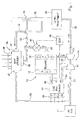
- an engine 10 includes a combustion air intake 12, an exhaust outlet 14 and a conventional turbo-compressor 18 which includes a turbine 20 and a compressor 22.
- An exhaust circuit includes an exhaust line 24 communicates engine exhaust from exhaust outlet 14 to the turbine 20.
- Exhaust line 26 communicates exhaust from turbine 20 to an exhaust after-treatment unit 28 (such as a particulate filter, a urea selective catalytic reducer, a lean NOx trap and/or a diesel oxidation catalyst).
- Exhaust outlet line 30 communicates exhaust from after-treatment unit 28 to the environment.
- An EGR line 32 communicates a portion of the exhaust from exhaust line 30 downstream of turbine 20 to an inlet 35 of EGR cooler 34.
- EGR cooler 34 includes an ambient air inlet 36, a cooled EGR outlet 38 and a heated air outlet 40.
- An air line 42 communicates heated air from outlet 40 to a venturi port 44 in the exhaust line 30 downstream of the after-treatment unit 28.
- venturi port 44 creates a suction or negative pressure which draws cooling air through cooler 34 and line 42.
- a bypass line 46 communicates ambient air to line 42.
- an electronically controlled valve 48 is installed in the bypass line 46 to control the flow therethrough.
- Valve 48 may be an on/off or a proportional valve.
- Air intake line 52 communicates a mixture of intake air from air inlet 50 and cooled exhaust gas from EGR cooler 34 to the compressor 22.
- Line 54 communicates the compressed mixture from compressor 22 to an inlet of a charge air cooler 56.
- Intake line 58 communicates cooled charge air from charge air cooler 56 to the engine intake 12.
- a fan 60 blows cooling air into the charge air cooler 56.
- a cooled EGR line 62 communicates cooled EGR from outlet 38 of EGR cooler 34 to a port in intake line 52 upstream of compressor 22.
- a parameter sensor preferably a temperature type sensor 64 senses the temperature of the mixture in line 58 and supplies an electronic temperature signal T to an electronic control unit ECU 66.
- the ECU 66 controls valve 46 in response to the sensed temperature.
- ECU 66 is programmed to cause valve 46 to fully or partially open if the sensed temperature approaches or falls below the dew point temperature. This reduces the flow of cooling air through cooler 34, increases the EGR temperature which flows out of cooler 34, and thus increases the temperature of the mixture in lines 54 and 58 and maintains the mixture temperature above the temperature at which condensation occurs.
- control valve regulates the flow of cooling air through the EGR cooler as a function of the temperature of the air/EGR mixture exiting the compressor. If this temperature approaches the dew point temperature, the flow is reduced which allows hotter exhaust gas to be combined with the charge air, thereby ensuring that the mixed temperature remains above the point at which condensation occurs.
- This system transfers heat directly to the ambient air. This is the most efficient way of removing the heat because it maintains the largest temperature difference possible. This system is also self-regulating. When the engine runs faster, more exhaust gas is created, the EGR flow increases, the entrained air flow rises and the amount of cooling increases. Also, the heat being removed is directed up and away from the tractor by the exhaust circuit, thereby reducing the risk of re-circulating the air into the cooling or combustion air systems. If necessary, a valve could be placed in line 32 to control the flow of EGR therethrough.
- FIG. 2 there is shown a simpler alternate embodiment similar to Fig. 1, but wherein the bypass inlet 46, valve 48, sensor 64 and ECU 66 are eliminated.
- increasing exhaust flow through line 30 increases the suction at venture 44. This increases the flow of cooling air through line 42 and increase the cooling effect upon EGR cooler 34. Conversely, decreasing exhaust flow decreases the flow of cooling air though line 42 and decreases the cooling effect upon EGR cooler 34.
Landscapes
- Engineering & Computer Science (AREA)
- Chemical & Material Sciences (AREA)
- Combustion & Propulsion (AREA)
- Mechanical Engineering (AREA)
- General Engineering & Computer Science (AREA)
- Physics & Mathematics (AREA)
- Thermal Sciences (AREA)
- Exhaust-Gas Circulating Devices (AREA)
Applications Claiming Priority (1)
| Application Number | Priority Date | Filing Date | Title |
|---|---|---|---|
| US11/207,309 US7322193B2 (en) | 2005-08-19 | 2005-08-19 | Exhaust gas recirculation system |
Publications (1)
| Publication Number | Publication Date |
|---|---|
| EP1754880A1 true EP1754880A1 (de) | 2007-02-21 |
Family
ID=37459549
Family Applications (1)
| Application Number | Title | Priority Date | Filing Date |
|---|---|---|---|
| EP06117456A Withdrawn EP1754880A1 (de) | 2005-08-19 | 2006-07-19 | Abgasrückführsystem |
Country Status (2)
| Country | Link |
|---|---|
| US (1) | US7322193B2 (de) |
| EP (1) | EP1754880A1 (de) |
Cited By (9)
| Publication number | Priority date | Publication date | Assignee | Title |
|---|---|---|---|---|
| GB2518009A (en) * | 2013-09-10 | 2015-03-11 | Gm Global Tech Operations Inc | System layout for an exhaust recirculation gas cooler |
| EP2406486A4 (de) * | 2009-03-13 | 2015-05-06 | Scania Cv Ab | Anordnung zur kühlung rückgeführter abgase in einem verbrennungsmotor |
| EP3573160A1 (de) * | 2018-05-22 | 2019-11-27 | Helmholtz-Zentrum Geesthacht Zentrum für Material- und Küstenforschung GmbH | Gaskreislaufsystem für den wärmetransport |
| CN114294092A (zh) * | 2021-11-19 | 2022-04-08 | 东风商用车有限公司 | 一种发动机用动态空气补偿与排温管理系统 |
| CN114294101A (zh) * | 2021-11-19 | 2022-04-08 | 东风商用车有限公司 | 柴油机动态空气补偿及热管理系统 |
| CN114294095A (zh) * | 2021-11-19 | 2022-04-08 | 东风商用车有限公司 | 发动机冷端动态空气补偿与旁通节气门后置排温管理系统 |
| CN114294098A (zh) * | 2021-11-19 | 2022-04-08 | 东风商用车有限公司 | 柴油机用动态空气补偿及排温管理系统 |
| CN114294097A (zh) * | 2021-11-19 | 2022-04-08 | 东风商用车有限公司 | 发动机热端动态空气补偿与旁通节气门后置排温管理系统 |
| CN114294100A (zh) * | 2021-11-19 | 2022-04-08 | 东风商用车有限公司 | 发动机用热端动态空气补偿与带加热装置的排温管理系统 |
Families Citing this family (38)
| Publication number | Priority date | Publication date | Assignee | Title |
|---|---|---|---|---|
| US7549412B2 (en) * | 1999-12-17 | 2009-06-23 | Satnarine Singh | System and method for recovering wasted energy from an internal combustion engine |
| SE528621C2 (sv) * | 2005-05-18 | 2006-12-27 | Scania Cv Ab | Arrangemang för återcirkulation av avgaser hos en överladdad förbränningsmotor |
| SE528620C2 (sv) * | 2005-05-18 | 2006-12-27 | Scania Cv Ab | Arrangemang för återcirkulation av avgaser hos en överladdad förbränningsmotor |
| DE102005042396A1 (de) * | 2005-09-06 | 2007-03-15 | Behr Gmbh & Co. Kg | Kühlsystem für ein Kraftfahrzeug |
| US20080264094A1 (en) * | 2007-04-30 | 2008-10-30 | Caterpillar Inc. | Cooling system with expansion driven fan |
| US7975479B2 (en) * | 2007-04-30 | 2011-07-12 | Caterpillar Inc. | Bi-material corrosive resistant heat exchanger |
| US7797937B2 (en) * | 2007-06-29 | 2010-09-21 | Caterpillar Inc | EGR equipped engine having condensation dispersion device |
| US7451750B1 (en) * | 2007-06-29 | 2008-11-18 | Caterpillar Inc. | Condensation reduction device for an EGR equipped system |
| US7798134B2 (en) * | 2008-05-07 | 2010-09-21 | General Electric Company | System, kit, and method for locomotive exhaust gas recirculation cooling |
| US7757678B2 (en) * | 2008-05-07 | 2010-07-20 | General Electric Company | Locomotive exhaust gas recirculation cooling |
| US20090313984A1 (en) * | 2008-06-24 | 2009-12-24 | Rez Mustafa | Hydraulic hybrid turbo transmission |
| US8087487B2 (en) * | 2008-11-12 | 2012-01-03 | Rez Mustafa | Hybrid turbo transmission |
| US8336304B2 (en) * | 2008-06-24 | 2012-12-25 | Rez Mustafa | Hydraulic hybrid turbo-transmission |
| US8235150B2 (en) * | 2008-06-24 | 2012-08-07 | Rez Mustafa | Pneumatic hybrid turbo transmission |
| SE533123C2 (sv) * | 2008-12-08 | 2010-06-29 | Scania Cv Ab | Arrangemang för kylning av återcirkulerande avgaser hos en förbränningsmotor |
| US8091359B2 (en) | 2010-06-03 | 2012-01-10 | Ford Global Technologies, Llc | Exhaust heat recovery for engine heating and exhaust cooling |
| US8056340B2 (en) * | 2010-08-17 | 2011-11-15 | Ford Global Technologies, Llc | EGR mixer for high-boost engine systems |
| US8783028B2 (en) * | 2011-08-16 | 2014-07-22 | Caterpillar Inc. | EGR performance balancing restrictor for an engine system |
| US20130061579A1 (en) * | 2011-09-14 | 2013-03-14 | Adam J. Kotrba | Exhaust Gas Aftertreatment System For Engines Equipped With Exhaust Gas Recirculation |
| US9151250B2 (en) | 2012-04-05 | 2015-10-06 | Donald B. Scoggins | Fluid cooling system |
| US9695785B2 (en) | 2013-11-11 | 2017-07-04 | Borgwarner Inc. | Turbocharger with integrated venturi mixer and EGR valve system |
| WO2015069330A1 (en) * | 2013-11-11 | 2015-05-14 | Borgwarner Inc. | Condensing egr-mixer system |
| WO2015140989A1 (ja) * | 2014-03-20 | 2015-09-24 | 日産自動車株式会社 | ディーゼルエンジンの制御装置及び制御方法 |
| US9551303B2 (en) | 2014-09-18 | 2017-01-24 | Caterpillar Inc. | Exhaust gas recirculation system for an internal combustion engine and method for operating same |
| US10138800B2 (en) | 2015-04-03 | 2018-11-27 | Cummins, Inc. | System and method for managing condensation in EGR systems |
| US9845772B2 (en) | 2015-04-30 | 2017-12-19 | Cummins, Inc. | System and method for managing condensation in EGR systems |
| US9845750B2 (en) | 2016-01-29 | 2017-12-19 | Ford Global Technologies, Llc | Method and system for exhaust gas heat recovery |
| US9689295B1 (en) | 2016-01-29 | 2017-06-27 | Ford Global Technologies, Llc | Method and system for exhaust gas heat recovery |
| US9957871B2 (en) | 2016-01-29 | 2018-05-01 | Ford Global Technologies, Llc | Exhaust heat recovery and hydrocarbon trapping |
| GB2551180A (en) * | 2016-06-09 | 2017-12-13 | Univ Of Huddersfield | Method and apparatus for charge air control |
| US11884904B2 (en) * | 2017-08-28 | 2024-01-30 | Icm, Inc. | Gas fermentation using multiple-pass trickle bed reactors |
| US10316803B2 (en) | 2017-09-25 | 2019-06-11 | Woodward, Inc. | Passive pumping for recirculating exhaust gas |
| US10995705B2 (en) | 2019-02-07 | 2021-05-04 | Woodward, Inc. | Modular exhaust gas recirculation system |
| KR102817281B1 (ko) * | 2019-11-19 | 2025-06-05 | 현대자동차 주식회사 | 인터쿨러 어셈블리 |
| CN213175878U (zh) | 2020-01-08 | 2021-05-11 | 伍德沃德有限公司 | 排气气体再循环混合器和发动机系统 |
| KR102152777B1 (ko) * | 2020-03-31 | 2020-09-07 | 에스티엑스엔진 주식회사 | 배기가스 흡입 장치 |
| US11174809B1 (en) | 2020-12-15 | 2021-11-16 | Woodward, Inc. | Controlling an internal combustion engine system |
| US11215132B1 (en) | 2020-12-15 | 2022-01-04 | Woodward, Inc. | Controlling an internal combustion engine system |
Citations (3)
| Publication number | Priority date | Publication date | Assignee | Title |
|---|---|---|---|---|
| JPH10176611A (ja) * | 1996-12-18 | 1998-06-30 | Isuzu Motors Ltd | Egrクーラー付きegr装置 |
| EP0869275A1 (de) * | 1997-03-31 | 1998-10-07 | Caterpillar Inc. | Abgasrückführungssystem für eine Brennkraftmaschine |
| US6216458B1 (en) | 1997-03-31 | 2001-04-17 | Caterpillar Inc. | Exhaust gas recirculation system |
Family Cites Families (10)
| Publication number | Priority date | Publication date | Assignee | Title |
|---|---|---|---|---|
| US4094284A (en) * | 1975-10-21 | 1978-06-13 | Eltra Corporation | Emission control system |
| US6205775B1 (en) * | 1999-03-22 | 2001-03-27 | Caterpillar Inc. | Exhaust gas recirculation control system |
| US6543428B1 (en) * | 2000-06-14 | 2003-04-08 | Caterpillar Inc. | Intake air separation system for an internal combustion engine |
| US6453893B1 (en) * | 2000-06-14 | 2002-09-24 | Caterpillar Inc | Intake air separation system for an internal combustion engine |
| US6598584B2 (en) * | 2001-02-23 | 2003-07-29 | Clean Air Partners, Inc. | Gas-fueled, compression ignition engine with maximized pilot ignition intensity |
| US6609374B2 (en) * | 2001-12-19 | 2003-08-26 | Caterpillar Inc | Bypass venturi assembly for an exhaust gas recirculation system |
| US20060179824A1 (en) * | 2003-02-03 | 2006-08-17 | Chapeau, Inc. | Air flow regulation system for exhaust stream oxidation catalyst |
| US7131271B2 (en) * | 2003-08-28 | 2006-11-07 | International Engine Intellectual Property Company, Llc | Clean, low-pressure EGR in a turbocharged engine by back-pressure control |
| US7013879B2 (en) * | 2003-11-17 | 2006-03-21 | Honeywell International, Inc. | Dual and hybrid EGR systems for use with turbocharged engine |
| US7356987B2 (en) * | 2004-07-30 | 2008-04-15 | Caterpillar Inc. | Exhaust gas recirculation system having an electrostatic precipitator |
-
2005
- 2005-08-19 US US11/207,309 patent/US7322193B2/en not_active Expired - Fee Related
-
2006
- 2006-07-19 EP EP06117456A patent/EP1754880A1/de not_active Withdrawn
Patent Citations (3)
| Publication number | Priority date | Publication date | Assignee | Title |
|---|---|---|---|---|
| JPH10176611A (ja) * | 1996-12-18 | 1998-06-30 | Isuzu Motors Ltd | Egrクーラー付きegr装置 |
| EP0869275A1 (de) * | 1997-03-31 | 1998-10-07 | Caterpillar Inc. | Abgasrückführungssystem für eine Brennkraftmaschine |
| US6216458B1 (en) | 1997-03-31 | 2001-04-17 | Caterpillar Inc. | Exhaust gas recirculation system |
Cited By (18)
| Publication number | Priority date | Publication date | Assignee | Title |
|---|---|---|---|---|
| EP2406486A4 (de) * | 2009-03-13 | 2015-05-06 | Scania Cv Ab | Anordnung zur kühlung rückgeführter abgase in einem verbrennungsmotor |
| GB2518009A (en) * | 2013-09-10 | 2015-03-11 | Gm Global Tech Operations Inc | System layout for an exhaust recirculation gas cooler |
| EP3573160A1 (de) * | 2018-05-22 | 2019-11-27 | Helmholtz-Zentrum Geesthacht Zentrum für Material- und Küstenforschung GmbH | Gaskreislaufsystem für den wärmetransport |
| JP2019204776A (ja) * | 2018-05-22 | 2019-11-28 | ヘルムホルツ−ツェントルム ゲーストハハト ツェントルム フュアー マテリアル ウント キュステンフォルシュンク ゲーエムベーハー | 熱移送用ガス循環システム |
| JP7102365B2 (ja) | 2018-05-22 | 2022-07-19 | ヘルムホルツ-ツェントルム ヘレオン ゲーエムベーハー | 熱移送用ガス循環システム |
| US11329299B2 (en) | 2018-05-22 | 2022-05-10 | Helmholtz-Zentrum Hereon Gmbh | Gas circulation system for transporting heat from a high temperature source |
| CN114294097A (zh) * | 2021-11-19 | 2022-04-08 | 东风商用车有限公司 | 发动机热端动态空气补偿与旁通节气门后置排温管理系统 |
| CN114294098A (zh) * | 2021-11-19 | 2022-04-08 | 东风商用车有限公司 | 柴油机用动态空气补偿及排温管理系统 |
| CN114294095A (zh) * | 2021-11-19 | 2022-04-08 | 东风商用车有限公司 | 发动机冷端动态空气补偿与旁通节气门后置排温管理系统 |
| CN114294100A (zh) * | 2021-11-19 | 2022-04-08 | 东风商用车有限公司 | 发动机用热端动态空气补偿与带加热装置的排温管理系统 |
| CN114294101A (zh) * | 2021-11-19 | 2022-04-08 | 东风商用车有限公司 | 柴油机动态空气补偿及热管理系统 |
| CN114294092A (zh) * | 2021-11-19 | 2022-04-08 | 东风商用车有限公司 | 一种发动机用动态空气补偿与排温管理系统 |
| CN114294097B (zh) * | 2021-11-19 | 2023-05-23 | 东风商用车有限公司 | 发动机热端动态空气补偿与旁通节气门后置排温管理系统 |
| CN114294095B (zh) * | 2021-11-19 | 2023-05-23 | 东风商用车有限公司 | 发动机冷端动态空气补偿与旁通节气门后置排温管理系统 |
| CN114294100B (zh) * | 2021-11-19 | 2023-05-23 | 东风商用车有限公司 | 发动机用热端动态空气补偿与带加热装置的排温管理系统 |
| CN114294092B (zh) * | 2021-11-19 | 2023-05-23 | 东风商用车有限公司 | 一种发动机用动态空气补偿与排温管理系统 |
| CN114294101B (zh) * | 2021-11-19 | 2023-05-23 | 东风商用车有限公司 | 柴油机动态空气补偿及热管理系统 |
| CN114294098B (zh) * | 2021-11-19 | 2023-05-23 | 东风商用车有限公司 | 柴油机用动态空气补偿及排温管理系统 |
Also Published As
| Publication number | Publication date |
|---|---|
| US20070039322A1 (en) | 2007-02-22 |
| US7322193B2 (en) | 2008-01-29 |
Similar Documents
| Publication | Publication Date | Title |
|---|---|---|
| US7322193B2 (en) | Exhaust gas recirculation system | |
| CN102007280B (zh) | 用于增压内燃发动机的冷却装置 | |
| US7530336B2 (en) | Intake condensation removal for internal combustion engine | |
| CN101542099B (zh) | 用于增压内燃机的废气的再循环的装置 | |
| CN101883920B (zh) | 用于燃烧发动机中废气的返回的装置和方法 | |
| US6216458B1 (en) | Exhaust gas recirculation system | |
| CN101960116B (zh) | 增压内燃发动机中的装置 | |
| KR101648866B1 (ko) | 연소 기관의 재순환 배기 가스 냉각 장치 | |
| EP2357351B1 (de) | Abgasrückführungssystem (EGR) und Energiesystem | |
| RU2449136C1 (ru) | Устройство для двигателя внутреннего сгорания с наддувом | |
| CN101405494B (zh) | 车辆内的冷却器装置 | |
| US8726657B2 (en) | Air turbine driven EGR pump for diesel engines | |
| US7757678B2 (en) | Locomotive exhaust gas recirculation cooling | |
| CN102066713B (zh) | 用于增压燃烧发动机的冷却装置 | |
| CN101553659B (zh) | 车辆的冷却装置 | |
| CN111102060B (zh) | 增压发动机系统及其冷凝控制方法 | |
| CN105201614B (zh) | 用于内燃机的冷却系统 | |
| JP2018021510A (ja) | 凝縮水抑制装置 | |
| CN111140410A (zh) | 用于使具有具备排气再循环的内燃发动机的机动车辆运转的方法 | |
| EP1550796A1 (de) | Verfahren und Vorrichtung zur Kontrolle der Abgastemperatur eines Motors | |
| EP1674681A2 (de) | Verfahren zum regeln einer abgasreinigunssystemtemperatur eines brennkraftmaschine und brennkraftmaschine | |
| CN103790697A (zh) | 防止涡轮增压机动车辆内燃发动机的压缩机上游的冷凝物形成的方法和设备 | |
| SE525197C2 (sv) | Anordning för reglering av temperaturen hos avgaser från ett avgassystem försett med aktivt regenererbart filter | |
| WO1988006679A1 (en) | Apparatus and method for treating air from a turbocharger | |
| US12378934B2 (en) | Low-pressure EGR system with condensate management |
Legal Events
| Date | Code | Title | Description |
|---|---|---|---|
| PUAI | Public reference made under article 153(3) epc to a published international application that has entered the european phase |
Free format text: ORIGINAL CODE: 0009012 |
|
| AK | Designated contracting states |
Kind code of ref document: A1 Designated state(s): AT BE BG CH CY CZ DE DK EE ES FI FR GB GR HU IE IS IT LI LT LU LV MC NL PL PT RO SE SI SK TR |
|
| AX | Request for extension of the european patent |
Extension state: AL BA HR MK YU |
|
| 17P | Request for examination filed |
Effective date: 20070821 |
|
| 17Q | First examination report despatched |
Effective date: 20070920 |
|
| AKX | Designation fees paid |
Designated state(s): DE GB |
|
| STAA | Information on the status of an ep patent application or granted ep patent |
Free format text: STATUS: THE APPLICATION IS DEEMED TO BE WITHDRAWN |
|
| 18D | Application deemed to be withdrawn |
Effective date: 20081108 |