EP1754894A2 - Elément de connexion à ajustement serré et sa méthode de fabrication - Google Patents
Elément de connexion à ajustement serré et sa méthode de fabrication Download PDFInfo
- Publication number
- EP1754894A2 EP1754894A2 EP06025191A EP06025191A EP1754894A2 EP 1754894 A2 EP1754894 A2 EP 1754894A2 EP 06025191 A EP06025191 A EP 06025191A EP 06025191 A EP06025191 A EP 06025191A EP 1754894 A2 EP1754894 A2 EP 1754894A2
- Authority
- EP
- European Patent Office
- Prior art keywords
- press
- fit
- outer diameter
- connection element
- head
- Prior art date
- Legal status (The legal status is an assumption and is not a legal conclusion. Google has not performed a legal analysis and makes no representation as to the accuracy of the status listed.)
- Granted
Links
- 238000004519 manufacturing process Methods 0.000 title claims description 15
- 238000000034 method Methods 0.000 claims abstract 3
- 230000000630 rising effect Effects 0.000 claims description 12
- 230000004323 axial length Effects 0.000 claims description 4
- 238000005096 rolling process Methods 0.000 claims description 4
- 238000005520 cutting process Methods 0.000 claims description 3
- 230000007423 decrease Effects 0.000 claims description 3
- 238000013461 design Methods 0.000 description 6
- 239000000463 material Substances 0.000 description 6
- 238000005553 drilling Methods 0.000 description 5
- 230000000694 effects Effects 0.000 description 4
- 238000003780 insertion Methods 0.000 description 3
- 230000037431 insertion Effects 0.000 description 3
- 238000009434 installation Methods 0.000 description 3
- 238000012545 processing Methods 0.000 description 3
- 230000000153 supplemental effect Effects 0.000 description 3
- 230000015572 biosynthetic process Effects 0.000 description 2
- 238000003825 pressing Methods 0.000 description 2
- 238000010008 shearing Methods 0.000 description 2
- 238000012549 training Methods 0.000 description 2
- 230000007704 transition Effects 0.000 description 2
- NPPQSCRMBWNHMW-UHFFFAOYSA-N Meprobamate Chemical compound NC(=O)OCC(C)(CCC)COC(N)=O NPPQSCRMBWNHMW-UHFFFAOYSA-N 0.000 description 1
- 229910000831 Steel Inorganic materials 0.000 description 1
- XAGFODPZIPBFFR-UHFFFAOYSA-N aluminium Chemical compound [Al] XAGFODPZIPBFFR-UHFFFAOYSA-N 0.000 description 1
- 229910052782 aluminium Inorganic materials 0.000 description 1
- 238000013459 approach Methods 0.000 description 1
- 230000000295 complement effect Effects 0.000 description 1
- 238000009826 distribution Methods 0.000 description 1
- 238000005516 engineering process Methods 0.000 description 1
- 238000001125 extrusion Methods 0.000 description 1
- CPJSUEIXXCENMM-UHFFFAOYSA-N phenacetin Chemical compound CCOC1=CC=C(NC(C)=O)C=C1 CPJSUEIXXCENMM-UHFFFAOYSA-N 0.000 description 1
- 239000010959 steel Substances 0.000 description 1
Images





Classifications
-
- F—MECHANICAL ENGINEERING; LIGHTING; HEATING; WEAPONS; BLASTING
- F16—ENGINEERING ELEMENTS AND UNITS; GENERAL MEASURES FOR PRODUCING AND MAINTAINING EFFECTIVE FUNCTIONING OF MACHINES OR INSTALLATIONS; THERMAL INSULATION IN GENERAL
- F16B—DEVICES FOR FASTENING OR SECURING CONSTRUCTIONAL ELEMENTS OR MACHINE PARTS TOGETHER, e.g. NAILS, BOLTS, CIRCLIPS, CLAMPS, CLIPS OR WEDGES; JOINTS OR JOINTING
- F16B35/00—Screw-bolts; Stay-bolts; Screw-threaded studs; Screws; Set screws
- F16B35/04—Screw-bolts; Stay-bolts; Screw-threaded studs; Screws; Set screws with specially-shaped head or shaft in order to fix the bolt on or in an object
- F16B35/041—Specially-shaped shafts
- F16B35/048—Specially-shaped necks
-
- F—MECHANICAL ENGINEERING; LIGHTING; HEATING; WEAPONS; BLASTING
- F16—ENGINEERING ELEMENTS AND UNITS; GENERAL MEASURES FOR PRODUCING AND MAINTAINING EFFECTIVE FUNCTIONING OF MACHINES OR INSTALLATIONS; THERMAL INSULATION IN GENERAL
- F16B—DEVICES FOR FASTENING OR SECURING CONSTRUCTIONAL ELEMENTS OR MACHINE PARTS TOGETHER, e.g. NAILS, BOLTS, CIRCLIPS, CLAMPS, CLIPS OR WEDGES; JOINTS OR JOINTING
- F16B4/00—Shrinkage connections, e.g. assembled with the parts at different temperature; Force fits; Non-releasable friction-grip fastenings
- F16B4/004—Press fits, force fits, interference fits, i.e. fits without heat or chemical treatment
Definitions
- the invention relates to a press-fit connecting element having a shaft, a head adjoining the shaft and a press-fit section provided on the shaft with a helical profile with an inlet region.
- Such press-fit connection elements serve in combination with a corresponding bore arranged in a component for producing a press-fit connection. Irrespective of the tolerance pairing of the press-fit connection present in the concrete individual case, the outer diameter of the press-fit section always has a certain excess compared to the inner diameter of the bore, from which the desired secure frictional connection results.
- a Presspassharmselement in particular a wheel bolt, is from the DE 43 18 494 C1 known.
- the press-fit connection element has a shank, a head adjoining the shank and a press-fit section provided with a multi-turn helical profile on the shank.
- the spiral profile has, like every thread, an inlet area and an outlet area.
- the helical profile has several threads with a corresponding pitch.
- the known Presspassitatiselement is always used in conjunction with a reworked hole in the component. Theoretically, it would be possible to dispense with a reworking of the bore or the bore could have a relatively large tolerance for other reasons. Such a non-reworked bore then has a tolerance in the range of IT 10 to IT 12. This means that the difference of the amounts of the inner diameter of the largest hole produced within the tolerance field and the smallest hole produced within the tolerance field is relatively large. Now, if the known press-fit connecting element would be pressed into such a bore in the component with a comparatively large inner diameter, the overlap and the resulting friction was insufficient to ensure the interference fit securely. There is a risk that the press-fit connection element unintentionally releases from the bore.
- the invention has for its object to provide a press-fit connection element, which can be pressed with good security effect and reusability in a machined with a relatively large tolerance bore.
- the object of the invention is achieved by a press-fit connection element having the features of independent claim 1 and by a method for producing a press-fit connection element having the features of independent claim 12.
- the axial knurled wheel bolt has a knurled press-fit section with axially extending knurls, ie with a multiplicity of adjacent ribs and grooves extending parallel to each other.
- a connecting element for connecting two components under prestressing is known from US 3,418,012 known.
- the known connecting element has a tapered swaging portion with substantially axially extending channels and ribs. In contrast to a thread or helical profile, the channels and ribs are either exactly axial, ie with a pitch of 90 °, or arranged with a slightly smaller pitch.
- the connecting element is introduced into two mutually aligned bores in the two components arranged one above the other.
- the bores were previously introduced together in such a way in the two components, that the diameter of the cylindrical bore is approximately between 25 microns [1/1000 inch] to 30 microns [12/1000 inch] smaller than the immediately below the head arranged maximum diameter of the Shaft of the connecting element.
- the connecting element is introduced under rotation into the bore. This results in an elastic-plastic deformation of the initially cylindrical bore, which also receives a conical design due to the frusto-conical geometry of the shaft of the connecting element.
- Press-fit fasteners with a shank, a head adjoining the shank and a press-fit portion with a knurl provided on the shank are known from US Pat GB 891,807 and the US 3,252,495 known.
- the knurl consists of spaced, parallel, around the screw axis encircling Rändelaboughen.
- the knurling sections have knurling elements which extend substantially in the direction of the screw axis.
- the knurling elements are inclined at an angle of about 10 ° with respect to the screw axis to ensure rotation of the press-fit connection element upon insertion into a corresponding bore.
- the new press-fit connection element has a shaft, a head adjoining the shaft and a press-fit section provided on the shaft with a helical profile with an inlet region.
- the press-fit portion has, in addition to the lead-in area, a rise area in which the outer diameter of the press-fit portion increases toward the head up to a maximum outer diameter with the maximum outer diameter of the rise area of the press-fit portion spaced from the head.
- press-fit connections - for example between wheel bolts and the hub of a car or truck - can be made safely and reliably, even with relatively large tolerances of the bores in the hub.
- the press-fit connection element according to the invention is pressed into a bore with a comparatively small inner diameter, then in the rise region of the press-fit section -d. H. a region with an outer diameter increasing toward the head, but smaller than the maximum outer diameter of the press-fit portion, to no or at least lower elastic-plastic deformations than in the region of the maximum outer diameter of the press-fit portion.
- the occurrence of undesirable stresses in the component and the press-fit connector is reduced, and the press-fit connector and corresponding bore member can be reused after the first release of the press-fit connection to reestablish a secure press-fit connection.
- the riser portion of the press-fit portion terminates spaced from the head of the connector to prevent the occurrence of undesirable near-head stresses and possible concomitant jackpot losses.
- the rise area of the press-fit portion is to be distinguished from the run-in area present in each helical profile.
- a helix is a continuous recess which winds around the screw axis and has projections provided between the individual turns of the depression and which likewise extends helically around the helix axis.
- manufacturing technology due to a slight increase in the outer diameter. In conventional helical profiles according to the prior art, however, this increase in the outer diameter does not continue.
- the known press-fit section has a constant core diameter and a constant outside diameter over the axial length.
- the press-fit section according to the invention or the spiral profile arranged therein has at least also outside the inlet area the rise area with an increasing outside diameter. It is preferred that the core diameter of the helical profile is constant.
- a plurality of further regions may be provided in the press-fit section, wherein the regions z. B. have different slopes with respect to their outer diameter or may be interconnected by cylindrical complementary areas.
- all of these different embodiments have in common that there is at least one rising region in which the outer diameter of the press-fitting section increases until the maximum outer diameter is reached.
- the rise range ends at this point. If this is followed by a cylindrical area with the maximum outer diameter, then this is referred to as supplementary area. Depending on further embodiment, this supplementary area can then extend over a more or less large axial portion of the press-fit section.
- the press-fitting portion may have, in addition to the rising portion, at least one descent region in which the outer diameter of the press-fitting portion decreases toward the head.
- the descent region can be formed in particular mirror-symmetrically to the rise area, which in particular brings manufacturing advantages with it, because thus the emergence of resultant axial forces is avoided in particular the rolling on the press-fit connection element.
- the material stress is reduced in the critical edge zones of the component.
- the press-fit portion may have a barrel-like shape.
- a barrel-shaped form can be produced particularly well by rolling.
- the adjacent points in both axial directions due to the relatively small pitch and deformations encountered when inserting the press-fit connection member into a bore, are also virtually the maximum outside diameter. This ensures that a sufficient axial range is available for the desired coverage.
- the press-fit section can be designed such that the entire helical profile is used to produce a press-fit connection.
- a part of the helical profile has a shortage over the inner diameter of the bore - d.
- a clearance fit or transitional fit forms - and only one next in the direction of the increasing outer diameter following part of the helical profile has the necessary excess to provide the desired interference fit.
- a cylindrical supplementary area which has the maximum outer diameter.
- a cylindrical supplementary area can also be provided in addition to the rise area.
- This supplemental area then has a certain axial extent, so that the rise area ends at a distance from the head of the connecting element.
- the cylindrical supplemental area also terminates spaced from the head of the connector to prevent the occurrence of undesirable stresses. In this way it is ensured that the area of the maximum diameter - d. H. its axial extent - is sufficient to achieve the desired tight interference fit.
- the cylindrical supplementary portion may be provided between the rising portion and the descending portion of the press-fitting portion.
- the helical profile can be designed more smoothly and in particular at least six.
- the pitch angle of the helical profile can in particular be between 5 ° and 30 °. Depending on the configuration of the helical profile and the Presspassabitess also significantly more courses may be present, for. B. up to 18 gears.
- the pitch angle is preferably between 9 ° and 11 °.
- the pitch angle is to be understood as the angle between an imaginary line running perpendicular to the axis of the connecting element and the helices.
- the selection of the pitch angle in a range of between 5 ° and 30 ° - preferably between 9 ° and 11 ° - has the advantage that displaced by the outer surfaces of the coil displaced material of the inner surface of the bore is less elastic-plastically deformed, as this is the case at larger and smaller angles.
- a threaded portion may be provided with a thread having a pitch diameter.
- the helical profile may have a core diameter that is greater than or equal to the pitch diameter of the thread. Due to this design, the helical profile has a stress cross section which is preferably about 15% or more greater than the stress cross section of the thread.
- the spiral profile has a significantly lower profile height than a normal thread.
- a centering whose outer diameter is greater than the outer diameter of the thread and preferably smaller than the minimum outer diameter of the helical profile in the inlet region.
- the centering portion serves to facilitate the axial insertion of the press-fit connection element into the corresponding bore in the component.
- this centering has a frusto-conical shape, whereby the desired centering effect is achieved safely when inserting the centering in the bore of the component.
- the centering approach preferably has no profile and may have an outer diameter which corresponds approximately to the pitch diameter of the thread.
- the centering portion may have an axial length corresponding to between 10% and 50%, preferably 25%, of the maximum outer diameter of the press-fit portion. This dimensioning ensures that an undesirable oblique insertion of the press-fit connection element into the bore is avoided.
- the press-fit connection element may be a wheel bolt.
- wheel bolts are used to connect the hub of a car or truck with the rim of a wheel.
- the wheel bolt is connected by means of the press-fit connection with the hub.
- a nut is screwed onto the threaded end of the wheel bolt arranged at the end.
- the press-fit connection element according to the invention can also be used for the production of all other press-fit connections.
- the coverage of the interference fit is a minimum of about 0.25% and a maximum of about 1.1%, resulting in a coverage window of about 0.85%.
- DE 43 18 494 C1 Page 4, lines 36-38 were previously known in spiral profiles overlaps in the range of 0.3 to 0.7%. This results in a coverage window of 0.4%. With the A new overlay window can be used to reduce the cost of producing the new press-fit connection.
- the new method of manufacturing a press-fit fastener having a shank and a head includes the steps of cold-forming a press-fit portion provided on the shank of the press-fit fastener to produce a cylindrical helical profile, and cutting the helix profile to produce a rise area in which the outer diameter of the press-fit portion is oriented in the direction up to a maximum outer diameter increases such that the maximum outer diameter of the rising portion of the press-fitting portion is spaced from the head.
- Non-cutting calibration can be done in particular by rolling or by shafts. This can be advantageous to generate a high areal proportion of the helical profile.
- the helical profile preferably has a surface carrying portion of at least about 30%.
- the surface carrying portion may be between about 30% and 80%, preferably between 40% and 70%, preferably about 50-60%.
- In the surface support portion is the area at the outer diameter of the helical profile, which has after completion of the press-fitting of the press-fit portion in the corresponding bore contact with the inner wall of the bore.
- the percentage indication of the areal component is based on the cylindrical surface area of the bore, it being assumed that the bore and the press-fit portion coincide in their axial length.
- the core diameter of the helical profile remains approximately constant during the calibration of the helical profile in the rise area.
- the outer diameter of the helical profile is preferably calibrated so precisely that it lies in a very accurate tolerance range of IT 7. As a result, the requirements for the tolerance of the corresponding hole in the component are reduced.
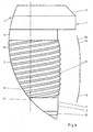
- FIG. 1 shows a first embodiment of the new press-fit connection element 1.
- the press-fit connection element 1 has a shaft 2 and a head 3 adjoining the shaft 2.
- a press-fit section 4 with a multi-turn helical profile 5 is also provided on the shaft 2.
- the exemplary spiral profile 5 shown in Fig. 1 is a six-speed helical profile 5.
- the helical profile 5 could also have more gears - for example, up to 18 gears.
- the spiral profile has an inlet region 6 and an outlet region 7.
- the press-fit section 4 has, in addition to the inlet region 6, a rise region 8 in which the outside diameter of the press-fit section 4 increases in the direction of the head 3 up to a maximum outside diameter.
- the slope of the rise area 8 is greatly exaggerated for reasons of clarity. In reality, the difference between the maximum outer diameter of the helical profile 5 and the minimum outer diameter of the helical profile 5 is much smaller. It is z. B. in the order of 5/100 mm. By contrast, the core diameter of the helical profile 5 is approximately constant over the length of the helical profile 5.
- the maximum outer diameter of the rising region 8 of the press-fit section 4 is arranged at a distance from the head 3. Between the outlet region 7 of the helical profile 5 and the underside of the head 3, a distance region 9 is provided. In addition to the rising portion 8, the press-fitting portion 4 has a descent portion 10 in which the outer diameter of the press-fitting portion 4 decreases toward the head 3.
- the Presspassabites 4 has a total of a slightly barrel-shaped or spherical shape.
- a centering section 11 is provided following the inlet region 6 of the helical profile 5 in the direction away from the head 3.
- the centering section 11 has a cylindrical part 12.
- Another frustoconical part 13 adjoins the centering section 11. By definition, it is not part of the centering section 11.
- the initial diameter of the centering section 11 is smaller than the minimum outer diameter of the helical profile 5 in the inlet region 6.
- a threaded section 14 with a thread 15 is arranged. It can be a metric or another thread.
- the diameter of the frusto-conical portion 13 of the centering portion 11 increases to a value larger than the value of the outer diameter of the thread 15 of the threaded portion 14.
- the press-fit connection element 1 shows a position of the new press-fit connection element 1 shortly before the production of the desired press-fit connection with a component 16.
- the component 16 may in particular be the hub of a car or truck.
- the press-fit connection element 1 is accordingly a wheel bolt 18.
- the component 16 has a bore 19, which extends as a through-bore through the component 16.
- the bore 19 is preferably a mere by drilling - d. H. without subsequent further processing - produced bore with a tolerance of IT 10 to IT 12.
- the press-fit connection element 1 is pressed by a pure axial force into the corresponding bore 19 of the component 16.
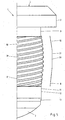
- Fig. 2 shows a second embodiment of the press-fit connection element 1 according to the invention, wherein in this embodiment, only the head 3 has a slightly different design.
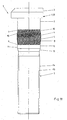
- FIGS. 1 and 2 Details of the helical profile 5 according to FIGS. 1 and 2 are shown in FIG .
- Fig. 3 in particular the (graphically exaggerated) barrel-shaped design of the helical profile 5 of the Presspassabitess 4 is clearly visible.
- This training is additionally represented symbolically by a line 20.
- FIG. 4 shows a further embodiment of the helical profile 5, it being apparent from the line 20 that a rise area 8, a descent area 10 and a cylindrical supplementary area 21 are provided, the cylindrical supplementary area 21 extending between the mirror-symmetrical areas 8, 10 , The transition between the areas 8, 10 on the one hand and 21 on the other hand is provided in this embodiment with a radius.
- the helical profile 5 may also have a linear or pointed course instead of the radius described above.
- FIG. 7 illustrates a similar embodiment to FIG. 6, again using a radius.
- FIG. 8 shows the press-fit connection element 1 in its position mounted in the component 16. It can be seen that, at least in the area of the maximum diameter of the press-fit section 4 or of the helical profile 5, such an overlap exists between the outer diameter of the helical profile 5 and the inner diameter of the bore 19 that there is a secure interference fit.
- the representations of the rise area 9 and also of the descent area 10 are greatly exaggerated for better understanding, however.
- a clearance fit results at the ends of the helical profile 5.
- the helical profile 5 can also be designed so that in the entire region of the helical profile 5 is present a press fit.
- the degree of overlap at the beginning of the rise area 8 is lower, so that overall when pressing the new press-fit connection element 1 into the bore 19 lower elastic-plastic deformations occur than in the prior art.
- the range of maximum overlap, or maximum diameter is chosen to be large enough to achieve the desired secure interference fit for all tolerance pairings.
- FIG. 9 shows a section of the connection point between the head 3 of the press-fit connection element 1 and the component 16.
- a circumferential groove 22 provided on the underside of the head 3, it is possible to dispense with the attachment of a chamfer to the component 16.
- the groove 22 ensures that the head 3 contacts the upper surface of the component 16 with its lower bearing surface and that no large laying force losses due to burrs or the like occur.
- FIG. 10 shows the formation of the head 3 with a stop 23.
- the stop 23 is used in the mounted position to prevent unwanted rotation of the connecting element 1 in the bore 19.
- Fig. 10 shows the six-start training of the helical profile 5.
- the press-fit connection element shows a further embodiment of the press-fit connection element, in which case the press-fit section 4 and the helical profile 5 are even further spaced from the head 3 are arranged. Accordingly, the distance region 9 has a greater axial extent.
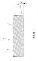
- Fig. 12 illustrates the pitch angle ⁇ of the helical profile 5.
- the pitch angle ⁇ is in a range of 10 °.
- FIG. 13 shows two concrete installation situations of the new press-fit connection element 1, the first installation situation being shown above the symmetry line and the second installation situation below the symmetry line.
- the Presspassitatiselements 1 is in the form of a wheel bolt 18 and fixedly connected to the hub 17 of a car or truck.
- a rim 24 is fixed to the hub 17 by means of the press-fit connection member 1 and a nut 25.
- the rim 24 shown above the line of symmetry has a relatively large wall thickness. For example, this is an aluminum rim.
- the rim 24 shown below the symmetry line has a relatively small wall thickness. For example, this is a steel rim.
Landscapes
- Engineering & Computer Science (AREA)
- General Engineering & Computer Science (AREA)
- Mechanical Engineering (AREA)
- Automatic Assembly (AREA)
- Forging (AREA)
- Connection Of Plates (AREA)
- Connections Arranged To Contact A Plurality Of Conductors (AREA)
- Multi-Conductor Connections (AREA)
- Connector Housings Or Holding Contact Members (AREA)
- Mutual Connection Of Rods And Tubes (AREA)
- Coupling Device And Connection With Printed Circuit (AREA)
Applications Claiming Priority (2)
| Application Number | Priority Date | Filing Date | Title |
|---|---|---|---|
| DE10258149A DE10258149B4 (de) | 2002-12-10 | 2002-12-10 | Presspassverbindungselement und Verfahren zu dessen Herstellung |
| EP03025143A EP1429039A1 (fr) | 2002-12-10 | 2003-11-03 | Elément de connexion à ajustement serré et sa méthode de fabrication |
Related Parent Applications (2)
| Application Number | Title | Priority Date | Filing Date |
|---|---|---|---|
| EP03025143.3 Division | 2003-11-03 | ||
| EP03025143A Division EP1429039A1 (fr) | 2002-12-10 | 2003-11-03 | Elément de connexion à ajustement serré et sa méthode de fabrication |
Publications (3)
| Publication Number | Publication Date |
|---|---|
| EP1754894A2 true EP1754894A2 (fr) | 2007-02-21 |
| EP1754894A3 EP1754894A3 (fr) | 2008-12-10 |
| EP1754894B1 EP1754894B1 (fr) | 2010-12-22 |
Family
ID=32319072
Family Applications (2)
| Application Number | Title | Priority Date | Filing Date |
|---|---|---|---|
| EP03025143A Withdrawn EP1429039A1 (fr) | 2002-12-10 | 2003-11-03 | Elément de connexion à ajustement serré et sa méthode de fabrication |
| EP06025191A Expired - Lifetime EP1754894B1 (fr) | 2002-12-10 | 2003-11-03 | Elément de connexion à ajustement serré et sa méthode de fabrication |
Family Applications Before (1)
| Application Number | Title | Priority Date | Filing Date |
|---|---|---|---|
| EP03025143A Withdrawn EP1429039A1 (fr) | 2002-12-10 | 2003-11-03 | Elément de connexion à ajustement serré et sa méthode de fabrication |
Country Status (6)
| Country | Link |
|---|---|
| US (1) | US7153075B2 (fr) |
| EP (2) | EP1429039A1 (fr) |
| AT (1) | ATE492732T1 (fr) |
| BR (2) | BRPI0305840B1 (fr) |
| DE (3) | DE10258149B4 (fr) |
| ES (1) | ES2356055T3 (fr) |
Families Citing this family (20)
| Publication number | Priority date | Publication date | Assignee | Title |
|---|---|---|---|---|
| DE10258149B4 (de) * | 2002-12-10 | 2006-04-06 | Kamax-Werke Rudolf Kellermann Gmbh & Co. Kg | Presspassverbindungselement und Verfahren zu dessen Herstellung |
| US7296957B2 (en) * | 2004-05-06 | 2007-11-20 | General Electric Company | Methods and apparatus for coupling gas turbine engine components |
| SE527767C2 (sv) * | 2004-10-22 | 2006-05-30 | Volvo Lastvagnar Ab | Fästelement |
| WO2008051171A1 (fr) * | 2006-10-27 | 2008-05-02 | Besel Bijon Makina Sanayi Ve Ticaret Anonim Sirketi | Mode de réalisation d'un boulon de roue à profil de section carrée |
| GB2446815C (en) * | 2006-12-20 | 2012-10-03 | Avdel Gb Ltd | Blind stud insert. |
| EP2843247B1 (fr) * | 2007-08-06 | 2022-02-16 | Nancy Tedeschi | Vis avec rupture et procédés d'utilisation de celle-ci |
| EP2047811B1 (fr) * | 2007-10-11 | 2011-03-30 | BIEDERMANN MOTECH GmbH | Fixation forcée pour fixer une barre dans un dispositif chirurgical, par exemple dans un dispositif de stabilisation de la colonne vertébrale |
| FR2923742B1 (fr) * | 2007-11-20 | 2010-04-02 | Prost Decolletage | Vis complexe et son procede de realisation |
| US7871108B2 (en) * | 2008-02-29 | 2011-01-18 | Caterpillar Inc | Machine mount |
| US8235345B2 (en) * | 2008-04-30 | 2012-08-07 | United Technologies Corp. | Gas turbine engine systems and related methods involving thermally isolated retention |
| DE102008001552A1 (de) * | 2008-05-05 | 2009-11-12 | Hilti Aktiengesellschaft | Befestigungsanordnung |
| US9644668B2 (en) | 2011-03-28 | 2017-05-09 | Wamlez Pty Ltd. | Fastener |
| US20120251264A1 (en) * | 2011-03-28 | 2012-10-04 | Wamlez Pty Ltd | Fastener |
| KR101143331B1 (ko) * | 2011-09-21 | 2012-05-09 | 지이엔 주식회사 | 다이아몬드 격자 구조형 인서트 너트 구조 및 이의 제조방법 |
| SG11201500475TA (en) * | 2012-07-17 | 2015-04-29 | Pem Man Inc | Tack screw |
| DE102013109284B4 (de) * | 2013-08-27 | 2017-04-06 | Thyssenkrupp Presta Aktiengesellschaft | Lenkwelle für eine Kraftfahrzeuglenkung |
| DE102014002951A1 (de) * | 2014-03-06 | 2015-09-10 | Nela Gmbh | Vorrichtung zum Glätten |
| JP2016027967A (ja) * | 2014-07-10 | 2016-02-25 | 株式会社ジェイテクト | ハブユニット |
| JP6916703B2 (ja) * | 2017-09-25 | 2021-08-11 | ジヤトコ株式会社 | 部品固定構造並びに部品固定方法 |
| DE102019120362B4 (de) | 2019-07-29 | 2026-01-15 | Kamax Holding Gmbh & Co. Kg | Befestigungselement |
Citations (4)
| Publication number | Priority date | Publication date | Assignee | Title |
|---|---|---|---|---|
| GB891807A (en) | 1959-02-18 | 1962-03-21 | Lamson & Sessions Co | Improvements in or relating to nut and bolt fasteners |
| US3252495A (en) | 1959-02-18 | 1966-05-24 | Lamson & Sessions Co | Bolt with a knurled barrel-shaped shank |
| US3418012A (en) | 1966-10-17 | 1968-12-24 | Mahoney Thomas P | Fastener for prestressing objects connected thereby |
| DE4318494C1 (de) | 1993-06-04 | 1995-02-16 | Kellermann Fa Rudolf | Preßpaßverbindungselement, insbesondere Radbolzen |
Family Cites Families (21)
| Publication number | Priority date | Publication date | Assignee | Title |
|---|---|---|---|---|
| US2024071A (en) * | 1932-07-28 | 1935-12-10 | Minnie E Sharp | Bolt |
| US2407928A (en) * | 1941-10-30 | 1946-09-17 | Chrysler Corp | Fastening device |
| US2650032A (en) * | 1949-12-08 | 1953-08-25 | American Brake Shoe Co | Track spike with circumferentially extending deformable projection |
| US2895368A (en) * | 1955-01-21 | 1959-07-21 | Jr Paul R Trigg | Bolt having rolled grooves and recessed head to enhance uniform elongation |
| FR74238E (fr) | 1958-10-02 | 1960-11-07 | Rhodiaceta | Perfectionnements au procédé de fabrication du papier |
| DE1804155U (de) * | 1959-11-04 | 1960-01-14 | Ford Werke Ag | Befestigungsbolzen. |
| FR1422358A (fr) * | 1964-11-13 | 1965-12-24 | Semt | Procédé de réalisation d'assemblages ou d'emmanchements d'au moins deux pièces soumises à des vibrations ou analogues |
| US3418013A (en) * | 1966-08-22 | 1968-12-24 | Ford Motor Co | Nonspinning threaded fastener |
| US3456972A (en) * | 1967-02-27 | 1969-07-22 | Ford Motor Co | Fastened assembly having a high resistance to varying shear loads |
| US4018132A (en) * | 1974-06-18 | 1977-04-19 | Tokai Cold Forming Co., Ltd. | Connecting-rod bolt |
| US4815907A (en) * | 1984-01-06 | 1989-03-28 | Hi-Shear Corporation | Eastener for structures made of composite materials |
| GB2220721B (en) * | 1988-07-11 | 1992-02-12 | Austin Rover Group | A method of making threaded fasteners |
| US5785478A (en) * | 1994-04-26 | 1998-07-28 | Rotter; Martin J. | Fastener |
| US5702214A (en) * | 1996-11-07 | 1997-12-30 | Avibank Mfg., Inc. | Non-removable structural fastener assembly |
| DE19754188A1 (de) * | 1997-12-06 | 1999-06-17 | Porsche Ag | Befestigungsvorrichtung für ein aus einer Radinnen- und einer Radaußenschale bestehendes Fahrzeugrad |
| JP3288969B2 (ja) * | 1998-04-07 | 2002-06-04 | 光洋精工株式会社 | 締結構造 |
| DE19900791B4 (de) * | 1999-01-12 | 2004-02-26 | Kamax-Werke Rudolf Kellermann Gmbh & Co. Kg | Verbindungselement für zwei Maschinen- oder Bauteile insbesondere Paß-Dehnschraube, Paß-Gewindebolzen o. dgl. |
| US6503038B2 (en) * | 2001-03-30 | 2003-01-07 | The United States Of America As Represented By The Secretary Of The Army | Reduced shank external flow passage bolt with integral pilot |
| DE10149017C2 (de) * | 2001-10-04 | 2003-08-21 | Kellermann Fa Rudolf | Lösbares Passverbindungselement für ein Bauteil, mit einer Passschraube und einem Stützring |
| AU2003218505A1 (en) * | 2002-04-22 | 2003-11-03 | Kenneth Lohr | Oversized wrenching head tension control bolt |
| DE10258149B4 (de) * | 2002-12-10 | 2006-04-06 | Kamax-Werke Rudolf Kellermann Gmbh & Co. Kg | Presspassverbindungselement und Verfahren zu dessen Herstellung |
-
2002
- 2002-12-10 DE DE10258149A patent/DE10258149B4/de not_active Expired - Fee Related
-
2003
- 2003-11-03 EP EP03025143A patent/EP1429039A1/fr not_active Withdrawn
- 2003-11-03 DE DE50313355T patent/DE50313355D1/de not_active Expired - Lifetime
- 2003-11-03 EP EP06025191A patent/EP1754894B1/fr not_active Expired - Lifetime
- 2003-11-03 DE DE20321399U patent/DE20321399U1/de not_active Expired - Lifetime
- 2003-11-03 ES ES06025191T patent/ES2356055T3/es not_active Expired - Lifetime
- 2003-11-03 AT AT06025191T patent/ATE492732T1/de active
- 2003-12-08 US US10/730,216 patent/US7153075B2/en not_active Expired - Lifetime
- 2003-12-10 BR BRPI0305840-9A patent/BRPI0305840B1/pt not_active IP Right Cessation
- 2003-12-10 BR BR0305840-9A patent/BR0305840A/pt active IP Right Grant
Patent Citations (4)
| Publication number | Priority date | Publication date | Assignee | Title |
|---|---|---|---|---|
| GB891807A (en) | 1959-02-18 | 1962-03-21 | Lamson & Sessions Co | Improvements in or relating to nut and bolt fasteners |
| US3252495A (en) | 1959-02-18 | 1966-05-24 | Lamson & Sessions Co | Bolt with a knurled barrel-shaped shank |
| US3418012A (en) | 1966-10-17 | 1968-12-24 | Mahoney Thomas P | Fastener for prestressing objects connected thereby |
| DE4318494C1 (de) | 1993-06-04 | 1995-02-16 | Kellermann Fa Rudolf | Preßpaßverbindungselement, insbesondere Radbolzen |
Non-Patent Citations (1)
| Title |
|---|
| Prospekt der Anmelderin "Radbolzen. Für PKW und Nutzfahrzeuge; KAMAX verbindet weltweit" (Ausgabe 2000). |
Also Published As
| Publication number | Publication date |
|---|---|
| DE10258149B4 (de) | 2006-04-06 |
| DE10258149A1 (de) | 2004-07-15 |
| DE50313355D1 (de) | 2011-02-03 |
| BR0305840A (pt) | 2004-08-31 |
| ES2356055T3 (es) | 2011-04-04 |
| ATE492732T1 (de) | 2011-01-15 |
| US20040115026A1 (en) | 2004-06-17 |
| BRPI0305840B1 (pt) | 2018-02-27 |
| EP1429039A1 (fr) | 2004-06-16 |
| EP1754894A3 (fr) | 2008-12-10 |
| EP1754894B1 (fr) | 2010-12-22 |
| US7153075B2 (en) | 2006-12-26 |
| DE20321399U1 (de) | 2007-02-08 |
Similar Documents
| Publication | Publication Date | Title |
|---|---|---|
| EP1754894B1 (fr) | Elément de connexion à ajustement serré et sa méthode de fabrication | |
| EP2893203B1 (fr) | Vis formant un trou et un taraudage pour le vissage direct de pièces sans pré-percer ainsi qu'assemblage de pièces ainsi réalisé | |
| EP0667936B1 (fr) | Procede de fabrication un element composite etre resistant a l'ejection et de se contourner par presser un element d'insertion dans une piece en tole et element d'insertion convenable pour ce procede | |
| EP1715198B1 (fr) | Arrangement de relation avec une pièce en plastique de porteur et un élément en plastique de fil | |
| EP2163773B1 (fr) | Vis à centrage automatique | |
| EP0627568B1 (fr) | Elément de connection et de centrage par insertion à force, en particulier boulon de roue | |
| EP1557574B1 (fr) | Ecrou à rivet aveugle | |
| EP2336581B1 (fr) | Pivot à rotule | |
| EP3044468B1 (fr) | Hélice pour insert fileté | |
| EP2638298B1 (fr) | Écrou auto-fileteur, élément tubulaire pour la fabrication de l'écrou et assemblage vissé composé d'un écrou et d'un boulon | |
| EP0678679A1 (fr) | Elément à montage par rivetage dans une pièce en tôle | |
| EP2857699B1 (fr) | Douille taraudée à visser | |
| EP3976977A1 (fr) | Élément de liaison | |
| EP1205676B1 (fr) | Unité de montage constituée d'un composant et d'au moins une vis | |
| EP3219442B1 (fr) | Élement d'entrainement d'un couple de rotation sur une cosse a insert filete | |
| EP1891341B1 (fr) | Boulon creux pourvu d'un alésage longitudinal et sa méthode de fabrication | |
| DE102010043805A1 (de) | Selbstsichernde Einstelleinrichtung und Fahrzeuglenkung | |
| EP3615265A1 (fr) | Élément de raccordement insérable par pressage et procédé d'ancrage d'éléments de raccordement insérables par pressage dans un matériau plat métallique à déformation permanente ou dans des composants et/ou pièces réalisés à partir de celui-ci | |
| EP2350487B1 (fr) | Ensemble frein à disque | |
| EP3473871B1 (fr) | Procédé de pose d'un élément formant rivet aveugle destiné à rigidifier deux sections disposées de manière espacée de deux composants ou d'un composant | |
| WO2025214676A1 (fr) | Élément de liaison à partie d'évacuation, ébauche pour la fabrication dudit élément de liaison et assemblage par vis comportant ledit élément de liaison | |
| DE102022130707A1 (de) | Schraube mit elektrisch leitendem zusatzmaterial | |
| WO2025131854A1 (fr) | Moyen de liaison, direction de véhicule, procédé de production d'un moyen de liaison et utilisation d'un moyen de liaison |
Legal Events
| Date | Code | Title | Description |
|---|---|---|---|
| PUAI | Public reference made under article 153(3) epc to a published international application that has entered the european phase |
Free format text: ORIGINAL CODE: 0009012 |
|
| AC | Divisional application: reference to earlier application |
Ref document number: 1429039 Country of ref document: EP Kind code of ref document: P |
|
| AK | Designated contracting states |
Kind code of ref document: A2 Designated state(s): AT BE BG CH CY CZ DE DK EE ES FI FR GB GR HU IE IT LI LU MC NL PT RO SE SI SK TR |
|
| PUAL | Search report despatched |
Free format text: ORIGINAL CODE: 0009013 |
|
| AK | Designated contracting states |
Kind code of ref document: A3 Designated state(s): AT BE BG CH CY CZ DE DK EE ES FI FR GB GR HU IE IT LI LU MC NL PT RO SE SI SK TR |
|
| 17P | Request for examination filed |
Effective date: 20090603 |
|
| 17Q | First examination report despatched |
Effective date: 20090715 |
|
| AKX | Designation fees paid |
Designated state(s): AT BE BG CH CY CZ DE DK EE ES FI FR GB GR HU IE IT LI LU MC NL PT RO SE SI SK TR |
|
| GRAP | Despatch of communication of intention to grant a patent |
Free format text: ORIGINAL CODE: EPIDOSNIGR1 |
|
| GRAS | Grant fee paid |
Free format text: ORIGINAL CODE: EPIDOSNIGR3 |
|
| GRAA | (expected) grant |
Free format text: ORIGINAL CODE: 0009210 |
|
| AC | Divisional application: reference to earlier application |
Ref document number: 1429039 Country of ref document: EP Kind code of ref document: P |
|
| AK | Designated contracting states |
Kind code of ref document: B1 Designated state(s): AT BE BG CH CY CZ DE DK EE ES FI FR GB GR HU IE IT LI LU MC NL PT RO SE SI SK TR |
|
| REG | Reference to a national code |
Ref country code: GB Ref legal event code: FG4D Free format text: NOT ENGLISH |
|
| REG | Reference to a national code |
Ref country code: CH Ref legal event code: EP |
|
| REG | Reference to a national code |
Ref country code: IE Ref legal event code: FG4D |
|
| REF | Corresponds to: |
Ref document number: 50313355 Country of ref document: DE Date of ref document: 20110203 Kind code of ref document: P |
|
| REG | Reference to a national code |
Ref country code: DE Ref legal event code: R096 Ref document number: 50313355 Country of ref document: DE Effective date: 20110203 |
|
| REG | Reference to a national code |
Ref country code: SE Ref legal event code: TRGR |
|
| REG | Reference to a national code |
Ref country code: NL Ref legal event code: T3 |
|
| REG | Reference to a national code |
Ref country code: ES Ref legal event code: FG2A Ref document number: 2356055 Country of ref document: ES Kind code of ref document: T3 Effective date: 20110404 |
|
| PG25 | Lapsed in a contracting state [announced via postgrant information from national office to epo] |
Ref country code: CY Free format text: LAPSE BECAUSE OF FAILURE TO SUBMIT A TRANSLATION OF THE DESCRIPTION OR TO PAY THE FEE WITHIN THE PRESCRIBED TIME-LIMIT Effective date: 20101222 Ref country code: BG Free format text: LAPSE BECAUSE OF FAILURE TO SUBMIT A TRANSLATION OF THE DESCRIPTION OR TO PAY THE FEE WITHIN THE PRESCRIBED TIME-LIMIT Effective date: 20110322 Ref country code: FI Free format text: LAPSE BECAUSE OF FAILURE TO SUBMIT A TRANSLATION OF THE DESCRIPTION OR TO PAY THE FEE WITHIN THE PRESCRIBED TIME-LIMIT Effective date: 20101222 Ref country code: SI Free format text: LAPSE BECAUSE OF FAILURE TO SUBMIT A TRANSLATION OF THE DESCRIPTION OR TO PAY THE FEE WITHIN THE PRESCRIBED TIME-LIMIT Effective date: 20101222 |
|
| REG | Reference to a national code |
Ref country code: SK Ref legal event code: T3 Ref document number: E 8932 Country of ref document: SK |
|
| REG | Reference to a national code |
Ref country code: IE Ref legal event code: FD4D |
|
| PG25 | Lapsed in a contracting state [announced via postgrant information from national office to epo] |
Ref country code: GR Free format text: LAPSE BECAUSE OF FAILURE TO SUBMIT A TRANSLATION OF THE DESCRIPTION OR TO PAY THE FEE WITHIN THE PRESCRIBED TIME-LIMIT Effective date: 20110323 Ref country code: EE Free format text: LAPSE BECAUSE OF FAILURE TO SUBMIT A TRANSLATION OF THE DESCRIPTION OR TO PAY THE FEE WITHIN THE PRESCRIBED TIME-LIMIT Effective date: 20101222 Ref country code: PT Free format text: LAPSE BECAUSE OF FAILURE TO SUBMIT A TRANSLATION OF THE DESCRIPTION OR TO PAY THE FEE WITHIN THE PRESCRIBED TIME-LIMIT Effective date: 20110422 |
|
| PG25 | Lapsed in a contracting state [announced via postgrant information from national office to epo] |
Ref country code: RO Free format text: LAPSE BECAUSE OF FAILURE TO SUBMIT A TRANSLATION OF THE DESCRIPTION OR TO PAY THE FEE WITHIN THE PRESCRIBED TIME-LIMIT Effective date: 20101222 |
|
| PLBE | No opposition filed within time limit |
Free format text: ORIGINAL CODE: 0009261 |
|
| STAA | Information on the status of an ep patent application or granted ep patent |
Free format text: STATUS: NO OPPOSITION FILED WITHIN TIME LIMIT |
|
| PG25 | Lapsed in a contracting state [announced via postgrant information from national office to epo] |
Ref country code: IE Free format text: LAPSE BECAUSE OF FAILURE TO SUBMIT A TRANSLATION OF THE DESCRIPTION OR TO PAY THE FEE WITHIN THE PRESCRIBED TIME-LIMIT Effective date: 20101222 Ref country code: DK Free format text: LAPSE BECAUSE OF FAILURE TO SUBMIT A TRANSLATION OF THE DESCRIPTION OR TO PAY THE FEE WITHIN THE PRESCRIBED TIME-LIMIT Effective date: 20101222 |
|
| 26N | No opposition filed |
Effective date: 20110923 |
|
| REG | Reference to a national code |
Ref country code: DE Ref legal event code: R097 Ref document number: 50313355 Country of ref document: DE Effective date: 20110923 |
|
| REG | Reference to a national code |
Ref country code: DE Ref legal event code: R081 Ref document number: 50313355 Country of ref document: DE Owner name: KAMAX HOLDING GMBH & CO. KG, DE Free format text: FORMER OWNER: KAMAX-WERKE RUDOLF KELLERMANN GMBH & CO. KG, 37520 OSTERODE, DE Effective date: 20120329 Ref country code: DE Ref legal event code: R082 Ref document number: 50313355 Country of ref document: DE Representative=s name: REHBERG HUEPPE + PARTNER PATENTANWAELTE PARTG , DE Effective date: 20120329 |
|
| PG25 | Lapsed in a contracting state [announced via postgrant information from national office to epo] |
Ref country code: MC Free format text: LAPSE BECAUSE OF NON-PAYMENT OF DUE FEES Effective date: 20111130 |
|
| REG | Reference to a national code |
Ref country code: CH Ref legal event code: PL |
|
| PG25 | Lapsed in a contracting state [announced via postgrant information from national office to epo] |
Ref country code: LI Free format text: LAPSE BECAUSE OF NON-PAYMENT OF DUE FEES Effective date: 20111130 Ref country code: CH Free format text: LAPSE BECAUSE OF NON-PAYMENT OF DUE FEES Effective date: 20111130 |
|
| REG | Reference to a national code |
Ref country code: NL Ref legal event code: TD Effective date: 20130328 |
|
| REG | Reference to a national code |
Ref country code: FR Ref legal event code: CD Owner name: KAMAX HOLDING GMBH & CO. KG, DE Effective date: 20130418 Ref country code: FR Ref legal event code: CA Effective date: 20130418 |
|
| PG25 | Lapsed in a contracting state [announced via postgrant information from national office to epo] |
Ref country code: LU Free format text: LAPSE BECAUSE OF NON-PAYMENT OF DUE FEES Effective date: 20111103 |
|
| REG | Reference to a national code |
Ref country code: ES Ref legal event code: PC2A Owner name: KAMAX HOLDING GMBH & CO.KG Effective date: 20130618 |
|
| REG | Reference to a national code |
Ref country code: SK Ref legal event code: TC4A Ref document number: E 8932 Country of ref document: SK Owner name: KAMAX HOLDING GMBH & CO. KG, HOMBERG (OHM), DE Effective date: 20130619 |
|
| PG25 | Lapsed in a contracting state [announced via postgrant information from national office to epo] |
Ref country code: TR Free format text: LAPSE BECAUSE OF FAILURE TO SUBMIT A TRANSLATION OF THE DESCRIPTION OR TO PAY THE FEE WITHIN THE PRESCRIBED TIME-LIMIT Effective date: 20101222 |
|
| PG25 | Lapsed in a contracting state [announced via postgrant information from national office to epo] |
Ref country code: HU Free format text: LAPSE BECAUSE OF FAILURE TO SUBMIT A TRANSLATION OF THE DESCRIPTION OR TO PAY THE FEE WITHIN THE PRESCRIBED TIME-LIMIT Effective date: 20101222 |
|
| REG | Reference to a national code |
Ref country code: FR Ref legal event code: PLFP Year of fee payment: 13 |
|
| PGFP | Annual fee paid to national office [announced via postgrant information from national office to epo] |
Ref country code: GB Payment date: 20151123 Year of fee payment: 13 |
|
| PGFP | Annual fee paid to national office [announced via postgrant information from national office to epo] |
Ref country code: NL Payment date: 20151124 Year of fee payment: 13 Ref country code: SE Payment date: 20151123 Year of fee payment: 13 Ref country code: AT Payment date: 20151120 Year of fee payment: 13 |
|
| REG | Reference to a national code |
Ref country code: FR Ref legal event code: PLFP Year of fee payment: 14 |
|
| REG | Reference to a national code |
Ref country code: SE Ref legal event code: EUG |
|
| REG | Reference to a national code |
Ref country code: NL Ref legal event code: MM Effective date: 20161201 |
|
| REG | Reference to a national code |
Ref country code: AT Ref legal event code: MM01 Ref document number: 492732 Country of ref document: AT Kind code of ref document: T Effective date: 20161103 |
|
| GBPC | Gb: european patent ceased through non-payment of renewal fee |
Effective date: 20161103 |
|
| PG25 | Lapsed in a contracting state [announced via postgrant information from national office to epo] |
Ref country code: AT Free format text: LAPSE BECAUSE OF NON-PAYMENT OF DUE FEES Effective date: 20161103 Ref country code: SE Free format text: LAPSE BECAUSE OF NON-PAYMENT OF DUE FEES Effective date: 20161104 |
|
| PG25 | Lapsed in a contracting state [announced via postgrant information from national office to epo] |
Ref country code: NL Free format text: LAPSE BECAUSE OF NON-PAYMENT OF DUE FEES Effective date: 20161201 |
|
| REG | Reference to a national code |
Ref country code: FR Ref legal event code: PLFP Year of fee payment: 15 |
|
| PG25 | Lapsed in a contracting state [announced via postgrant information from national office to epo] |
Ref country code: GB Free format text: LAPSE BECAUSE OF NON-PAYMENT OF DUE FEES Effective date: 20161103 |
|
| REG | Reference to a national code |
Ref country code: DE Ref legal event code: R082 Ref document number: 50313355 Country of ref document: DE Representative=s name: MUELLER SCHUPFNER & PARTNER PATENT- UND RECHTS, DE |
|
| PGFP | Annual fee paid to national office [announced via postgrant information from national office to epo] |
Ref country code: SK Payment date: 20221028 Year of fee payment: 20 Ref country code: IT Payment date: 20221130 Year of fee payment: 20 Ref country code: FR Payment date: 20221118 Year of fee payment: 20 Ref country code: ES Payment date: 20221216 Year of fee payment: 20 Ref country code: DE Payment date: 20220929 Year of fee payment: 20 Ref country code: CZ Payment date: 20221024 Year of fee payment: 20 |
|
| PGFP | Annual fee paid to national office [announced via postgrant information from national office to epo] |
Ref country code: BE Payment date: 20221118 Year of fee payment: 20 |
|
| P01 | Opt-out of the competence of the unified patent court (upc) registered |
Effective date: 20230420 |
|
| REG | Reference to a national code |
Ref country code: DE Ref legal event code: R071 Ref document number: 50313355 Country of ref document: DE |
|
| REG | Reference to a national code |
Ref country code: SK Ref legal event code: MK4A Ref document number: E 8932 Country of ref document: SK Expiry date: 20231103 |
|
| REG | Reference to a national code |
Ref country code: ES Ref legal event code: FD2A Effective date: 20231128 |
|
| REG | Reference to a national code |
Ref country code: BE Ref legal event code: MK Effective date: 20231103 |
|
| PG25 | Lapsed in a contracting state [announced via postgrant information from national office to epo] |
Ref country code: SK Free format text: LAPSE BECAUSE OF EXPIRATION OF PROTECTION Effective date: 20231103 |
|
| PG25 | Lapsed in a contracting state [announced via postgrant information from national office to epo] |
Ref country code: ES Free format text: LAPSE BECAUSE OF EXPIRATION OF PROTECTION Effective date: 20231104 |
|
| PG25 | Lapsed in a contracting state [announced via postgrant information from national office to epo] |
Ref country code: SK Free format text: LAPSE BECAUSE OF EXPIRATION OF PROTECTION Effective date: 20231103 Ref country code: ES Free format text: LAPSE BECAUSE OF EXPIRATION OF PROTECTION Effective date: 20231104 Ref country code: CZ Free format text: LAPSE BECAUSE OF EXPIRATION OF PROTECTION Effective date: 20231103 |