EP1754907A2 - Actionneur electromagnetique, embrayage avec cet actionneur et dispositif de transmission de puissance pour véhicule automobile - Google Patents
Actionneur electromagnetique, embrayage avec cet actionneur et dispositif de transmission de puissance pour véhicule automobile Download PDFInfo
- Publication number
- EP1754907A2 EP1754907A2 EP06013472A EP06013472A EP1754907A2 EP 1754907 A2 EP1754907 A2 EP 1754907A2 EP 06013472 A EP06013472 A EP 06013472A EP 06013472 A EP06013472 A EP 06013472A EP 1754907 A2 EP1754907 A2 EP 1754907A2
- Authority
- EP
- European Patent Office
- Prior art keywords
- permanent magnet
- yoke
- electromagnetic actuator
- armature
- coil
- Prior art date
- Legal status (The legal status is an assumption and is not a legal conclusion. Google has not performed a legal analysis and makes no representation as to the accuracy of the status listed.)
- Granted
Links
- 230000005540 biological transmission Effects 0.000 title claims description 15
- 230000005291 magnetic effect Effects 0.000 claims abstract description 60
- 230000004907 flux Effects 0.000 claims abstract description 25
- BGPVFRJUHWVFKM-UHFFFAOYSA-N N1=C2C=CC=CC2=[N+]([O-])C1(CC1)CCC21N=C1C=CC=CC1=[N+]2[O-] Chemical compound N1=C2C=CC=CC2=[N+]([O-])C1(CC1)CCC21N=C1C=CC=CC1=[N+]2[O-] BGPVFRJUHWVFKM-UHFFFAOYSA-N 0.000 description 38
- 238000010276 construction Methods 0.000 description 9
- 239000000446 fuel Substances 0.000 description 6
- RYGMFSIKBFXOCR-UHFFFAOYSA-N Copper Chemical compound [Cu] RYGMFSIKBFXOCR-UHFFFAOYSA-N 0.000 description 4
- 230000008859 change Effects 0.000 description 4
- 230000007246 mechanism Effects 0.000 description 4
- 230000005294 ferromagnetic effect Effects 0.000 description 3
- 239000000126 substance Substances 0.000 description 3
- 230000008878 coupling Effects 0.000 description 2
- 238000010168 coupling process Methods 0.000 description 2
- 238000005859 coupling reaction Methods 0.000 description 2
- 230000003247 decreasing effect Effects 0.000 description 2
- 230000000694 effects Effects 0.000 description 2
- 239000011347 resin Substances 0.000 description 2
- 229920005989 resin Polymers 0.000 description 2
- 230000004044 response Effects 0.000 description 2
- 238000010586 diagram Methods 0.000 description 1
- 238000005265 energy consumption Methods 0.000 description 1
- 238000012423 maintenance Methods 0.000 description 1
- 238000000034 method Methods 0.000 description 1
- 230000004048 modification Effects 0.000 description 1
- 238000012986 modification Methods 0.000 description 1
- 230000007935 neutral effect Effects 0.000 description 1
- 230000003014 reinforcing effect Effects 0.000 description 1
- 230000035939 shock Effects 0.000 description 1
- 238000004804 winding Methods 0.000 description 1
Images




Classifications
-
- F—MECHANICAL ENGINEERING; LIGHTING; HEATING; WEAPONS; BLASTING
- F16—ENGINEERING ELEMENTS AND UNITS; GENERAL MEASURES FOR PRODUCING AND MAINTAINING EFFECTIVE FUNCTIONING OF MACHINES OR INSTALLATIONS; THERMAL INSULATION IN GENERAL
- F16D—COUPLINGS FOR TRANSMITTING ROTATION; CLUTCHES; BRAKES
- F16D27/00—Magnetically- or electrically- actuated clutches; Control or electric circuits therefor
- F16D27/004—Magnetically- or electrically- actuated clutches; Control or electric circuits therefor with permanent magnets combined with electromagnets
-
- F—MECHANICAL ENGINEERING; LIGHTING; HEATING; WEAPONS; BLASTING
- F16—ENGINEERING ELEMENTS AND UNITS; GENERAL MEASURES FOR PRODUCING AND MAINTAINING EFFECTIVE FUNCTIONING OF MACHINES OR INSTALLATIONS; THERMAL INSULATION IN GENERAL
- F16D—COUPLINGS FOR TRANSMITTING ROTATION; CLUTCHES; BRAKES
- F16D27/00—Magnetically- or electrically- actuated clutches; Control or electric circuits therefor
- F16D27/10—Magnetically- or electrically- actuated clutches; Control or electric circuits therefor with an electromagnet not rotating with a clutching member, i.e. without collecting rings
- F16D27/108—Magnetically- or electrically- actuated clutches; Control or electric circuits therefor with an electromagnet not rotating with a clutching member, i.e. without collecting rings with axially movable clutching members
- F16D27/11—Magnetically- or electrically- actuated clutches; Control or electric circuits therefor with an electromagnet not rotating with a clutching member, i.e. without collecting rings with axially movable clutching members with conical friction surfaces, e.g. cone clutches
-
- F—MECHANICAL ENGINEERING; LIGHTING; HEATING; WEAPONS; BLASTING
- F16—ENGINEERING ELEMENTS AND UNITS; GENERAL MEASURES FOR PRODUCING AND MAINTAINING EFFECTIVE FUNCTIONING OF MACHINES OR INSTALLATIONS; THERMAL INSULATION IN GENERAL
- F16D—COUPLINGS FOR TRANSMITTING ROTATION; CLUTCHES; BRAKES
- F16D27/00—Magnetically- or electrically- actuated clutches; Control or electric circuits therefor
- F16D2027/005—Details relating to the internal construction of coils or to clutches having more than one coil in the same housing
-
- F—MECHANICAL ENGINEERING; LIGHTING; HEATING; WEAPONS; BLASTING
- F16—ENGINEERING ELEMENTS AND UNITS; GENERAL MEASURES FOR PRODUCING AND MAINTAINING EFFECTIVE FUNCTIONING OF MACHINES OR INSTALLATIONS; THERMAL INSULATION IN GENERAL
- F16D—COUPLINGS FOR TRANSMITTING ROTATION; CLUTCHES; BRAKES
- F16D27/00—Magnetically- or electrically- actuated clutches; Control or electric circuits therefor
- F16D2027/008—Details relating to the magnetic circuit, or to the shape of the clutch parts to achieve a certain magnetic path
Definitions
- the present invention relates to an electromagnetic actuator for an automobile, and in particular, to an electromagnetic actuator used for a clutch device arranged in a power train.
- a yoke and an armature which are formed of ferromagnetic substances are arranged in a magnetic field which is generated by energizing a magnet coil, and a force at the time of the yoke and armature which attract each other is taken out, and it is made a control force of the clutch.
- a request of reducing energy consumption of a magnet coil has created devices which each make a permanent magnet arranged in a magnetic circuit, and use magnetic flux which the permanent magnet generates.
- JP-A-2000-192996 discloses a devised clutch having a construction of energizing a magnet coil only at the time of switching a state (engagement and disengagement) of the clutch by installing a permanent magnet in a yoke, providing a control force, required for maintenance of a clutch engaging state, by the permanent magnet, and devising strength of an attractive force by the permanent magnet and a spring force of a return spring.
- the present invention may be equipped with a magnet coil, a yoke which transmits magnetic flux generated by energizing the magnet coil, an armature which is installed with keeping a predetermined gap with the yoke, transmits the magnetic flux which is emitted from the yoke, and is attracted toward through the yoke, a permanent magnet, and/or a switching electromagnet coil which controls the magnetic flux of the permanent magnet.
- the electromagnetic actuator used for a power train of an automobile can maintain a control force by an attractive force mainly caused by the embedded permanent magnet also in a situation that it is necessary to always generate the control force.
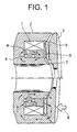
- Fig. 1 is a cross-sectional view of one embodiment of an electromagnetic actuator according to the present invention.
- a yoke 2 is made of a ferromagnetic substance, and has a circular shape with a U-shaped cross-section.
- An armature 3 is installed with a predetermined gap so as to cover an opening portion of the yoke 2.
- an electromagnetic coil 1 which is made of an annularly coiled copper wire and is molded with a resin is arranged.
- armature 3 Since a magnetic field is generated clockwise to a current around the electromagnetic coil 1 when the electromagnetic coil 1 is energized, magnetic flux by the electromagnetic coil 1 passes a portion, which is constructed of the yoke 2 and armature 3, so as to flow back.
- the armature 3 is supported by a guide which is not shown, and is movable in a direction of reducing the gap with the yoke 2 to be restrained in other directions. In addition, motion of the armature 3 is transferred to an operation target which is not shown.
- a permanent magnet 4 which is circular and is magnetized in an axial direction is further arranged inside the electromagnetic coil 1, and is arranged so that an S pole of the permanent magnet 4 may contact to the yoke 2 and an N pole may contact to a short-circuit magnetic circuit 5 which is made of a ferromagnetic substance.
- the short-circuit magnetic circuit 5 is arranged so that another side which does not contact to the permanent magnet 4 may contact the yoke 2.
- the short-circuit magnetic circuit 5 is provided so as to short-circuit magnetically the N pole, which is one magnetic pole of the permanent magnet 4, and the yoke 2.
- the switching electromagnet coil 6 is arranged in a region surrounded by the yoke 2, permanent magnet 4, and short-circuit magnetic circuit 5.
- the switching electromagnet coil 6 is also made of an annularly coiled copper wire and is molded with a resin.
- the permanent magnet 4, which is arranged in the yoke 2, the short-circuit magnetic circuit 5, electromagnetic coil 1, and switching electromagnet coil 6 are fixed with an inside C ring 7 and an outside C ring 8.
- electric power supply to the electromagnetic coil 1 and switching electromagnet coil 6 is performed by a controller which is not shown.
- the armature 3 is connected to the operation target and a force which the armature 3 receives is transmitted to the operation target.
- the short-circuit magnetic circuit 5 and the permanent magnet 4 which is annular and is magnetized in an axial direction are used in this embodiment, the short-circuit magnetic circuit 5 may be omitted as long as it is possible to exert a similar effect, or the permanent magnets 4 may be discal or rod-like. In addition, as long as it is possible to exert a similar effect, the arrangement of the permanent magnet 4, short-circuit magnetic circuit 5, electromagnetic coil 1, and switching electromagnet coil 6 may be another form.
- the switching electromagnet coil 6 applies a current in a direction of generating a magnetic field reverse to a direction of a magnetic field by the permanent magnet 4 at the time of no-energization as shown in Fig. 2. That is, as shown in Fig. 3, it is made that the magnetic field by the switching electromagnet coil 6 becomes counterclockwise against the clockwise magnetic field by the permanent magnet 4.
- the switching electromagnet coil 6 When the switching electromagnet coil 6 is energized, its magnetic field interferes with the magnetic field of the permanent magnet 4, and hence, an interference result changes according to a current value. As shown in Fig. 3, while a current is small, the magnetic fields of the permanent magnet 4 and switching electromagnet coil 6 operate so as to cancel each other, and differential magnetic flux after being cancelled generates a small force of attracting the armature 3.
- Fig. 5 shows a graph drawn by making the current value of the switching electromagnet coil 6 a horizontal axis, and making the attractive force of the armature 3 a vertical axis. The graph plots both results of presence and absence of the permanent magnet 4.
- an electromagnetic actuator when performing control to a state that a force is generated from a state that the force is not generated, first, the electromagnetic coil 1 is energized for a current to be adjusted, and a required force is generated. Next, when generating the force and holding it as it is, the switching electromagnet coil 6 is energized, and after a current which flows in the switching electromagnet coil 6 fully rises, energization of the electromagnetic coil 1 is stopped.
- the switching electromagnet coil 6 attracts the armature using a magnetomotive force of the permanent magnet 4, it is possible to hold the force with a smaller current in comparison with the electromagnetic coil 1. Thus, it is possible to hold the force of the electromagnetic actuator with the small current flowed through the switching electromagnet coil 6. In addition, since quick response in the switching electromagnet coil 6 is unnecessary, it is also sufficient to increase a number of windings with using a thinner copper wire to further reduce the current consumed.
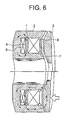
- Fig. 6 is a cross-sectional view of another embodiment of an electromagnetic actuator according to the present invention.
- the construction of the yoke 2, electromagnetic coil 1, and armature 3 is the same as that in the first embodiment shown in Fig. 1.
- Differences in this embodiment shown in Fig. 6 are that the discal permanent magnet 4 which is magnetized radially is arranged so as to contact to inside and outside portions of the yoke 2, that the switching electromagnet coil 6 is arranged in a region surrounded by the yoke 2 and permanent magnet 4, and that there is no short-circuit magnetic circuit 5.
- Generation of an attractive force by the electromagnetic coil 1 is similar to the first embodiment, and hence, it is possible to continuously control the attractive force by controlling the current.
- an electromagnetic actuator when performing control to a state that a force is generated from a state that the force is not generated, first, the electromagnetic coil 1 is energized for a current to be adjusted, and a required force is generated. Next, when generating the force and holding it as it is, the switching electromagnet coil 6 is energized, and after a current which flows in the switching electromagnet coil 6 fully rises, energization of the electromagnetic coil 1 is stopped. Since the switching electromagnet coil 6 attracts the armature 3 using a magnetomotive force of the permanent magnet 4, it is possible to hold the force with a smaller current in comparison with the electromagnetic coil 1. Thus, it is possible to hold the force of the electromagnetic actuator with the small current flowed through the switching electromagnet coil 6.
- Fig. 7 is a drawing showing a cross-section of an embodiment of a clutch device using the electromagnetic actuator 10 according to the present invention.
- the construction of the electromagnetic actuator 10 is the same as that in the first embodiment shown in Fig. 1.
- the yoke 2 of the electromagnetic actuator 10 is fixed to a clutch case 41 with bolts 42, the armature 3 is held by a guide 11, and they are arranged so that a force which presses a clutch pack 13 through a pressure plate 12 may act.
- the clutch pack 13 is arranged between a clutch guide 14 connected to an input shaft 21 and a clutch hub 16 connected to an output shaft 22.
- the clutch pack 13 controls engagement and disengagement of the clutch guide 14 and clutch hub 16, i.e., the input shaft 21 and output shaft 22 in a rotary direction.
- the input shaft 21 is held by an input shaft ball bearing 31 in the clutch case 41, and protrudes to the exterior through an oil seal 33.
- the clutch hub 16 is held by a clutch hub clamp 15 and a clutch hub ball bearing 32, and the output shaft 22 is held by another device not shown. Electric power supply to the electromagnetic coil 1 and switching electromagnet coil 6 is performed by a clutch controller which is not shown.
- the switching electromagnet coil 6 When maintaining an engaging state of the clutch, the switching electromagnet coil 6 is energized after making the clutch into an engaging state with the electromagnetic coil 1 as mentioned above. After the current which flows in the switching electromagnet coil 6 fully rises, energization of the electromagnetic coil 1 is stopped. On this occasion, the switching electromagnet coil 6 can use a magnetomotive force of the permanent magnet 4 to be able to hold a force required for clutch engagement with little power consumption.
- Fig. 8 is a drawing showing a cross-section of an embodiment of a transmission for a mobile having a clutch using the electromagnetic actuator 10 according to the present invention.
- the construction of the electromagnetic actuator 10 and clutch device is the same as that in the third embodiment shown in Fig. 7.
- a transmission is a device for a speed change of rotation of an engine of an automobile to transmit it to tires, and converting engine power into revolution speed suitable to a driving state.
- the input shaft 21 is connected to the engine and the output shaft 53 of the transmission is connected to tires.
- the transmission is installed in an engine room and is operated by electronic control equipment and an operation actuator which are not shown. Shift operation of the transmission is automatically executed by an order of electronic control equipment according to an operator's intention or driving state.
- the transmission has a first shaft 51, a second shaft 52, and an output shaft 53, and gears (G1, G2, G3, and G4 and M1, M2, M3, and M4) from whose sizes are different are arranged between the first shaft 51 and second shaft 52.
- Respective gears correspond to respective transmission levels, and this embodiment is a four-speed transmission having four sets of gears. However, a back gear for backing an automobile is not shown in this embodiment. In addition, the number of gears may be 4 or more.
- Respective gears are not fixed to a shaft on the second shaft 52, and are supported rotatably.
- Two synchromesh devices which couple each gear and the second shaft 52 are provided on the second shaft 53.
- the first synchro-mesh mechanism S1 has a role of synchronizing and coupling the second shaft gear M1 which is for the first speed, or the second shaft gear M2 which is for the second speed, with the second shaft 52.
- the second synchro-mesh mechanism S2 has a role of synchronizing and coupling the second shaft gear M3 which is for the third speed, or the second shaft gear M4 which is for the fourth speed, with the second shaft 53. That is, by operating the two synchro-mesh mechanisms, a gear used among from gears which are in an idle condition on the second shaft 52 is selected, and is coupled to the second shaft 52 to obtain a state of transmitting power by a desired gear.
- Rotation of the second shaft 52 is further transmitted to a third shaft by final gear MF and a ring gear AF.
- the rotation transmitted to the ring gear is transmitted to right and left tires, which are not shown, through a differential gear Dl which adjusts a rotational difference between the right and left tires of an automobile.
- the electromagnetic actuator 10 generates a control force of a clutch assembly 40, and operates this.
- the input shaft 21 and first shaft 51 are coupled in the clutch assembly. They are constructed so that the input shaft 21 and first shaft 51 may be separated when the clutch is a disengaged state, but the input shaft 21 and first shaft 51 may be coupled and may become the same rotation when the clutch is in an engaging state.
- the first synchromesh device S1 is operated by the operation actuator which is not shown, and the second shaft gear M1 for the first speed is coupled with the second shaft 52.
- the electromagnetic coil 1 of the electromagnetic actuator 10 is energized, and the control force of the clutch is generated gradually.
- the clutch transmits torque from the input shaft 21 to the first shaft 51.
- the torque is transmitted from the first shaft gear G1 for the first speed to the second shaft gear M2 for the first speed, further, it is transmitted from the second shaft 52 to the output shaft 53 through the final gear MF, ring gear AF, and differential gear D1, and it is transmitted to the tires which are not shown.
- the torque transmitted to the tires becomes a driving force which makes an automobile driven and automobile speed also rises gradually. After automobile speed fully rises, a current to the electromagnetic coil 1 is fully increased to increase the control force, and the clutch is fully engaged. In this state, the torque which the engine generates is transmitted to the tires without slip, and the automobile becomes in the driving state in the first speed.
- the electromagnetic actuator 10 consumes electric power continuously, and since that electric power is obtained by rotating a generator under engine power from the first, it becomes loss to worsen fuel consumption of the automobile. Then, the switching electromagnet coil 6 of the electromagnetic actuator 10 is energized, and switching is performed so that the control force by the permanent magnet 4 in the electromagnetic actuator 10 may be generated. After the switching, a current which is flowed in the electromagnetic coil 1 is stopped.
- the switching electromagnet coil 6 can accept slower response in comparison with the electromagnetic coil 1, it is made by a thin copper wire being wound many turns so as to operate under power saving. Thus, when maintaining the clutch in the engaging state, it is necessary not to worsen the fuel consumption of an automobile by saving electric power by energizing the switching electromagnet coil 6 to make the control force maintained by the attractive force which the permanent magnet 4 generates. Furthermore, for further power saving, it is also possible to take a form of corresponding only while an engine output is small by making the control force generated in a state that the switching electromagnet coil 6 is energized be a value smaller than a force required for operation of the clutch, and of corresponding at the engine output being increased by further energizing the electromagnetic coil 1 to increase the control force.
- the current which is energizing the switching electromagnet coil 6 is stopped.
- the current of the electromagnetic coil 1 is lowered with adjusting the torque which the engine generates, and the clutch is made disengaged so that a shock may not be generated.
- the first synchro-mesh mechanism S1 is operated by an operation actuator, which is not shown, for the second shaft gear M1 for the first speed to be decoupled from the second shaft 52, and subsequently, the second shaft gear M2 for the second speed is coupled with the second shaft 52.
- Pressure of the clutch is generated gradually by energizing the electromagnetic coil 1 of the electromagnetic actuator 10 to couple the input shaft 21 with the first shaft 51.
- the switching electromagnet coil 6 of the electromagnetic actuator 10 is energized, and switching is performed so that the control force by the permanent magnet 4 in the electromagnetic actuator 10 may be generated. After the switching, a current which is flowed in the electromagnetic coil 1 is stopped.
- a speed change to the third speed and fourth speed, and a reverse speed change, for example, from the fourth speed to the third speed, can be also executed in the similar procedure, and it is possible to maintain a driving state with small electric power required for the switching electromagnet coil 6 in the driving state.
- control device which controls energization of the electromagnetic coil 1 and switching electromagnet coil 6 will be explained using Fig. 9.
- the control device is not limited to the construction of this embodiment since what is necessary is just what controls energization of the electromagnetic coil 1 and switching electromagnet coil 6 as mentioned above.
- the control device of this embodiment is constructed of a controller 91, a current generator 94a which supplies a current to the electromagnetic coil 1, a switching circuit 92a which turns on and off energization from the current generator 94a, a current detector 93a which detects amplitude of the current which flows in the electromagnetic coil 1, a current generator 94b which supplies a current to the switching electromagnet coil 6, a switching circuit 92b which turns on and off energization from the current generator 94b, a current detector 93b which detects amplitude of the current which flows in the switching electromagnet coil 6, and the like.
- the controller 91 command the current generator 94a a current value which changes with time so that a desired attractive force may be obtained, while turning on the switching circuit 92a.
- the electromagnetic actuator 10 is driven by the order from an electronic controller which controls the clutch.
- This electronic controller may be also a controller 91, or may be also a controller different from the controller 91.
- the current generator 94a generates a current having a pattern which is commanded, and supplies it to the electromagnetic coil 1.
- the energization of the switching electromagnet coil 6 is started.
- the switching circuit 92b is turned on with the order from the controller 91, and a current is supplied to the switching electromagnet coil 6 from the current generator 94b.
- a power supply which always generates a predetermined voltage as a current generator 94b is used and the switching circuit 92b turns on and off the energization from this power supply. But, it is also good to control the current generator 94b so that the current supplied to the switching electromagnet coil 6 changes from the current generator 94b in a desired pattern.
- the controller 91 judges on the basis of the current value, detected in the current detector 93b, that the current which flows in the switching electromagnet coil 6 fully rises, the controller 91 issues an order to the switching circuit 92a and turns off the switching circuit 92a so as to stop the energization of the electromagnetic coil 1.
- the state that the armature 3 is attracted to the yoke 2 side with the smaller current in comparison with the electromagnetic coil 1 is held by making the switching electromagnet coil 6 attract the armature 3 using the magnetomotive force of the permanent magnet 4. That is, the state that the armature 3 is attracted to the yoke 2 side, magnetic flux from the switching electromagnet coil 6 and magnetic flux from the permanent magnet 4 are generated in the same direction to the armature 3.
Landscapes
- Engineering & Computer Science (AREA)
- General Engineering & Computer Science (AREA)
- Physics & Mathematics (AREA)
- Electromagnetism (AREA)
- Mechanical Engineering (AREA)
- Hydraulic Clutches, Magnetic Clutches, Fluid Clutches, And Fluid Joints (AREA)
- Reciprocating, Oscillating Or Vibrating Motors (AREA)
Applications Claiming Priority (1)
| Application Number | Priority Date | Filing Date | Title |
|---|---|---|---|
| JP2005190878A JP4625727B2 (ja) | 2005-06-30 | 2005-06-30 | 電磁アクチュエータ及びそれを用いたクラッチ機構及び自動車の動力伝達機構 |
Publications (3)
| Publication Number | Publication Date |
|---|---|
| EP1754907A2 true EP1754907A2 (fr) | 2007-02-21 |
| EP1754907A3 EP1754907A3 (fr) | 2009-11-11 |
| EP1754907B1 EP1754907B1 (fr) | 2010-11-03 |
Family
ID=37602974
Family Applications (1)
| Application Number | Title | Priority Date | Filing Date |
|---|---|---|---|
| EP06013472A Ceased EP1754907B1 (fr) | 2005-06-30 | 2006-06-29 | Actionneur electromagnetique, embrayage avec cet actionneur et dispositif de transmission de puissance pour véhicule automobile |
Country Status (4)
| Country | Link |
|---|---|
| US (1) | US20070035371A1 (fr) |
| EP (1) | EP1754907B1 (fr) |
| JP (1) | JP4625727B2 (fr) |
| DE (1) | DE602006017934D1 (fr) |
Cited By (3)
| Publication number | Priority date | Publication date | Assignee | Title |
|---|---|---|---|---|
| DE102007008831A1 (de) * | 2007-02-23 | 2008-08-28 | Conti Temic Microelectronic Gmbh | Kupplung |
| WO2016010918A1 (fr) * | 2014-07-13 | 2016-01-21 | Dana Automotive Systems Group, Llc | Procédé et système de verrouillage d'un actionneur |
| US10323699B2 (en) | 2015-07-02 | 2019-06-18 | Dana Automotive Systems Group, Llc | Electromagnetic connect/disconnect system for a vehicle |
Families Citing this family (8)
| Publication number | Priority date | Publication date | Assignee | Title |
|---|---|---|---|---|
| DE202007007385U1 (de) * | 2007-05-23 | 2007-11-29 | Kuhnke Automation Gmbh & Co. Kg | Betätigungsmagnet zum Bewegen einer Verschlussnadel einer Heißkanaldüse eines Spritzgusswerkzeuges |
| JP4596051B2 (ja) * | 2008-07-09 | 2010-12-08 | トヨタ自動車株式会社 | ツインクラッチ装置 |
| JP2010174944A (ja) * | 2009-01-28 | 2010-08-12 | Gkn Driveline Japan Ltd | 動力伝達装置 |
| WO2016028465A1 (fr) * | 2014-08-18 | 2016-02-25 | Eaton Corporation | Actionneur électromécanique de décalage de flux à verrouillage magnétique |
| EP3166116B1 (fr) | 2015-11-09 | 2020-10-28 | HUSCO Automotive Holdings LLC | Systèmes et procédés pour un actionneur électromagnétique |
| JP2017169433A (ja) * | 2016-03-17 | 2017-09-21 | フスコ オートモーティブ ホールディングス エル・エル・シーHUSCO Automotive Holdings LLC | 電磁アクチュエータのためのシステムおよび方法 |
| KR102309645B1 (ko) * | 2017-04-06 | 2021-10-08 | 한국자동차연구원 | 동력전달장치 |
| JP2019108986A (ja) * | 2019-02-28 | 2019-07-04 | シンフォニアテクノロジー株式会社 | 動力伝達装置 |
Family Cites Families (34)
| Publication number | Priority date | Publication date | Assignee | Title |
|---|---|---|---|---|
| US2695687A (en) * | 1952-07-02 | 1954-11-30 | Warner Electric Brake & Clutch | Magnetic friction device with replaceable friction face |
| US3089064A (en) * | 1958-02-08 | 1963-05-07 | Electro Chimie Metal | Combined permanent magnet and electromagnet |
| US2956658A (en) * | 1958-02-19 | 1960-10-18 | Eaton Mfg Co | Magnetic couplings |
| US3070730A (en) * | 1960-08-22 | 1962-12-25 | Bendix Corp | Three-position latching solenoid actuator |
| US3446321A (en) * | 1967-06-13 | 1969-05-27 | Mohawk Data Sciences Corp | Clutch-brake with permanent magnets |
| US3634735A (en) * | 1969-04-03 | 1972-01-11 | Mikio Komatsu | Self-holding electromagnetically driven device |
| US3842378A (en) * | 1973-07-20 | 1974-10-15 | Pitts Ind Inc | Double clutch for vehicle air conditioning compressor |
| US4127835A (en) * | 1977-07-06 | 1978-11-28 | Dynex/Rivett Inc. | Electromechanical force motor |
| US4547757A (en) * | 1981-04-17 | 1985-10-15 | Matsushita Electric Industrial Co., Ltd. | Electromagnet yoke structure |
| USRE34870E (en) * | 1981-11-16 | 1995-03-07 | Moog Inc. | Electro-mechanical actuator |
| DE3437106A1 (de) * | 1983-10-14 | 1985-05-02 | Equipements Automobiles Marchal S.A., Issy-les-Moulineaux | Elektromagnetische stelleinrichtung |
| CN1003822B (zh) * | 1984-10-09 | 1989-04-05 | 三菱矿业水泥株式会社 | 电磁执行机构 |
| US4905031A (en) * | 1987-12-14 | 1990-02-27 | Eastman Kodak Company | Axial magnetic actuator |
| DE3920978A1 (de) * | 1989-06-27 | 1991-01-10 | Fev Motorentech Gmbh & Co Kg | Elektromagnetisch arbeitende stelleinrichtung |
| US5119918A (en) * | 1991-10-11 | 1992-06-09 | Dana Corporation | Electromagnetic clutch with permanent magnet brake |
| US5365210A (en) * | 1993-09-21 | 1994-11-15 | Alliedsignal Inc. | Latching solenoid with manual override |
| JP3508523B2 (ja) * | 1997-12-19 | 2004-03-22 | 三菱電機株式会社 | 鉄心可動型リニア振動子及びリニア圧縮機 |
| JPH11287346A (ja) * | 1998-04-03 | 1999-10-19 | Ranco Japan Ltd | ソレノイドバルブ |
| US6371270B1 (en) * | 1999-07-05 | 2002-04-16 | Sanden Corporation | Electromagnetic clutch |
| DE10013516A1 (de) * | 2000-03-20 | 2001-09-27 | Kendrion Binder Magnete Gmbh | Bremsvorrichtung oder Kupplungsvorrichtung |
| JP4329250B2 (ja) * | 2000-09-20 | 2009-09-09 | 株式会社デンソー | 電磁式アクチュエータの製造方法 |
| US6634476B2 (en) * | 2000-10-20 | 2003-10-21 | Usui Kokusai Sangyo Kaisha, Limited | Magnet type fan clutch apparatus |
| CN1234135C (zh) * | 2001-01-18 | 2005-12-28 | 株式会社日立制作所 | 电磁铁和使用该电磁铁的开关装置的操作机构 |
| JP2002270423A (ja) * | 2001-03-07 | 2002-09-20 | Toshiba Corp | 電磁アクチュエータ及び開閉器 |
| JP4788084B2 (ja) * | 2001-08-21 | 2011-10-05 | いすゞ自動車株式会社 | 変速機のシフト操作装置 |
| GB2385470A (en) * | 2002-02-11 | 2003-08-20 | Ling Dynamic Systems | Vibrator - bearing and coil layout |
| DE10235644B4 (de) * | 2002-08-02 | 2004-10-21 | Eto Magnetic Kg | Elektromagnetische Stellvorrichtung |
| US6741151B1 (en) * | 2002-11-27 | 2004-05-25 | Levram Medical Systems, Ltd. | Moving coil linear actuator |
| JP2004190853A (ja) * | 2002-11-28 | 2004-07-08 | Usui Kokusai Sangyo Kaisha Ltd | マグネット式クラッチ装置 |
| JP2004308903A (ja) * | 2003-04-07 | 2004-11-04 | Luk Lamellen & Kupplungsbau Beteiligungs Kg | 電磁式の摩擦クラッチ |
| DE10324487B4 (de) * | 2003-05-30 | 2009-04-09 | Kendrion Binder Magnete Gmbh | Elektromagnetisch öffnende Polreibungskupplung oder Polreibungsbremse |
| US6791442B1 (en) * | 2003-11-21 | 2004-09-14 | Trombetta, Llc | Magnetic latching solenoid |
| JP4347100B2 (ja) * | 2004-03-17 | 2009-10-21 | Ntn株式会社 | ステアバイワイヤシステム |
| ITMI20041813A1 (it) * | 2004-09-22 | 2004-12-22 | Foussianes Nicholas B | Dispositivo di trasmissione del moto a ventole di raffreddamento di motori. |
-
2005
- 2005-06-30 JP JP2005190878A patent/JP4625727B2/ja not_active Expired - Fee Related
-
2006
- 2006-06-29 DE DE602006017934T patent/DE602006017934D1/de active Active
- 2006-06-29 EP EP06013472A patent/EP1754907B1/fr not_active Ceased
- 2006-06-29 US US11/476,741 patent/US20070035371A1/en not_active Abandoned
Non-Patent Citations (1)
| Title |
|---|
| None |
Cited By (4)
| Publication number | Priority date | Publication date | Assignee | Title |
|---|---|---|---|---|
| DE102007008831A1 (de) * | 2007-02-23 | 2008-08-28 | Conti Temic Microelectronic Gmbh | Kupplung |
| WO2016010918A1 (fr) * | 2014-07-13 | 2016-01-21 | Dana Automotive Systems Group, Llc | Procédé et système de verrouillage d'un actionneur |
| US10436258B2 (en) | 2014-07-13 | 2019-10-08 | Dana Automotive Systems Group, Llc | Method and system for latching an actuator |
| US10323699B2 (en) | 2015-07-02 | 2019-06-18 | Dana Automotive Systems Group, Llc | Electromagnetic connect/disconnect system for a vehicle |
Also Published As
| Publication number | Publication date |
|---|---|
| DE602006017934D1 (de) | 2010-12-16 |
| JP2007014105A (ja) | 2007-01-18 |
| JP4625727B2 (ja) | 2011-02-02 |
| EP1754907A3 (fr) | 2009-11-11 |
| EP1754907B1 (fr) | 2010-11-03 |
| US20070035371A1 (en) | 2007-02-15 |
Similar Documents
| Publication | Publication Date | Title |
|---|---|---|
| US9184646B2 (en) | Starter machine system and method | |
| EP1754907B1 (fr) | Actionneur electromagnetique, embrayage avec cet actionneur et dispositif de transmission de puissance pour véhicule automobile | |
| US10914347B2 (en) | Clutch system | |
| JP5659936B2 (ja) | スタータ | |
| US6792821B1 (en) | Shifting device for a transmission | |
| JP2004125126A (ja) | 電磁ソレノイドおよびこれを用いた変速機のシフトアクチュエータ | |
| US20110127133A1 (en) | Twin-clutch device | |
| US5523636A (en) | Electromagnetically controlled gear engagement mechanism integrated with a magnetic hysteresis slip clutch | |
| CN101310429A (zh) | 线性致动器 | |
| US6935477B2 (en) | Magnet type clutch device or magnet type fan clutch device | |
| JPH10213221A (ja) | 変速操作装置 | |
| Poltschak et al. | Completely integrated electromagnetic dog clutch actuator for automotive applications | |
| KR20210071064A (ko) | 전기자 해제 칼라를 가진 회전 커플링 장치 | |
| JP2002210288A (ja) | 全自動洗濯機 | |
| KR101647787B1 (ko) | 에스컬레이터의 완속 제동을 위한 클러치 장치 | |
| AU681293B2 (en) | Electromagnetically controlled gear engagement mechanism integrated with a magnetic hysteresis slip clutch | |
| US20260063177A1 (en) | Solenoid-type clutch device | |
| JPH04151030A (ja) | 電磁クラッチ | |
| JPH0447179B2 (fr) | ||
| JP2010112442A (ja) | 圧縮機用電磁クラッチ | |
| JP2004019738A (ja) | 自動変速機の駆動装置 | |
| JP2002286127A (ja) | 変速機のシフト操作装置 | |
| JP2002070697A (ja) | スタータ用マグネチックスイッチ及びその製造方法並びにスタータ | |
| WO2025254057A1 (fr) | Solénoïde | |
| JPH07293595A (ja) | 電磁クラッチ装置 |
Legal Events
| Date | Code | Title | Description |
|---|---|---|---|
| PUAI | Public reference made under article 153(3) epc to a published international application that has entered the european phase |
Free format text: ORIGINAL CODE: 0009012 |
|
| AK | Designated contracting states |
Kind code of ref document: A2 Designated state(s): AT BE BG CH CY CZ DE DK EE ES FI FR GB GR HU IE IS IT LI LT LU LV MC NL PL PT RO SE SI SK TR |
|
| AX | Request for extension of the european patent |
Extension state: AL BA HR MK YU |
|
| 17P | Request for examination filed |
Effective date: 20090409 |
|
| PUAL | Search report despatched |
Free format text: ORIGINAL CODE: 0009013 |
|
| AK | Designated contracting states |
Kind code of ref document: A3 Designated state(s): AT BE BG CH CY CZ DE DK EE ES FI FR GB GR HU IE IS IT LI LT LU LV MC NL PL PT RO SE SI SK TR |
|
| AX | Request for extension of the european patent |
Extension state: AL BA HR MK RS |
|
| GRAP | Despatch of communication of intention to grant a patent |
Free format text: ORIGINAL CODE: EPIDOSNIGR1 |
|
| GRAS | Grant fee paid |
Free format text: ORIGINAL CODE: EPIDOSNIGR3 |
|
| AKX | Designation fees paid |
Designated state(s): DE FR |
|
| GRAA | (expected) grant |
Free format text: ORIGINAL CODE: 0009210 |
|
| AK | Designated contracting states |
Kind code of ref document: B1 Designated state(s): DE FR |
|
| REF | Corresponds to: |
Ref document number: 602006017934 Country of ref document: DE Date of ref document: 20101216 Kind code of ref document: P |
|
| PLBE | No opposition filed within time limit |
Free format text: ORIGINAL CODE: 0009261 |
|
| STAA | Information on the status of an ep patent application or granted ep patent |
Free format text: STATUS: NO OPPOSITION FILED WITHIN TIME LIMIT |
|
| 26N | No opposition filed |
Effective date: 20110804 |
|
| REG | Reference to a national code |
Ref country code: DE Ref legal event code: R097 Ref document number: 602006017934 Country of ref document: DE Effective date: 20110804 |
|
| REG | Reference to a national code |
Ref country code: FR Ref legal event code: PLFP Year of fee payment: 11 |
|
| REG | Reference to a national code |
Ref country code: FR Ref legal event code: PLFP Year of fee payment: 12 |
|
| REG | Reference to a national code |
Ref country code: FR Ref legal event code: PLFP Year of fee payment: 13 |
|
| PGFP | Annual fee paid to national office [announced via postgrant information from national office to epo] |
Ref country code: FR Payment date: 20200512 Year of fee payment: 15 Ref country code: DE Payment date: 20200617 Year of fee payment: 15 |
|
| REG | Reference to a national code |
Ref country code: DE Ref legal event code: R119 Ref document number: 602006017934 Country of ref document: DE |
|
| PG25 | Lapsed in a contracting state [announced via postgrant information from national office to epo] |
Ref country code: DE Free format text: LAPSE BECAUSE OF NON-PAYMENT OF DUE FEES Effective date: 20220101 |
|
| PG25 | Lapsed in a contracting state [announced via postgrant information from national office to epo] |
Ref country code: FR Free format text: LAPSE BECAUSE OF NON-PAYMENT OF DUE FEES Effective date: 20210630 |