EP1754934A1 - Dispositif pour fixer un projecteur sur un étrier - Google Patents
Dispositif pour fixer un projecteur sur un étrier Download PDFInfo
- Publication number
- EP1754934A1 EP1754934A1 EP06017226A EP06017226A EP1754934A1 EP 1754934 A1 EP1754934 A1 EP 1754934A1 EP 06017226 A EP06017226 A EP 06017226A EP 06017226 A EP06017226 A EP 06017226A EP 1754934 A1 EP1754934 A1 EP 1754934A1
- Authority
- EP
- European Patent Office
- Prior art keywords
- housing
- headlight
- bracket
- bearing
- rail
- Prior art date
- Legal status (The legal status is an assumption and is not a legal conclusion. Google has not performed a legal analysis and makes no representation as to the accuracy of the status listed.)
- Granted
Links
Images



Classifications
-
- F—MECHANICAL ENGINEERING; LIGHTING; HEATING; WEAPONS; BLASTING
- F21—LIGHTING
- F21V—FUNCTIONAL FEATURES OR DETAILS OF LIGHTING DEVICES OR SYSTEMS THEREOF; STRUCTURAL COMBINATIONS OF LIGHTING DEVICES WITH OTHER ARTICLES, NOT OTHERWISE PROVIDED FOR
- F21V21/00—Supporting, suspending, or attaching arrangements for lighting devices; Hand grips
- F21V21/14—Adjustable mountings
- F21V21/30—Pivoted housings or frames
-
- F—MECHANICAL ENGINEERING; LIGHTING; HEATING; WEAPONS; BLASTING
- F21—LIGHTING
- F21W—INDEXING SCHEME ASSOCIATED WITH SUBCLASSES F21K, F21L, F21S and F21V, RELATING TO USES OR APPLICATIONS OF LIGHTING DEVICES OR SYSTEMS
- F21W2131/00—Use or application of lighting devices or systems not provided for in codes F21W2102/00-F21W2121/00
- F21W2131/40—Lighting for industrial, commercial, recreational or military use
- F21W2131/406—Lighting for industrial, commercial, recreational or military use for theatres, stages or film studios
Definitions
- the invention relates to a device for connecting a headlamp with a bracket according to the preamble of claim 1.
- Stage, studio, film, television or event lighting fixtures can be used standing in conjunction with a tripod or suspended in conjunction with a studio suspension called a rig via a bar control with or without a motorized remote control.
- the connection of the headlight with a tripod or rig takes place with a for the standing or hanging mounting of the headlight about the headlight housing pivotable bracket whose arms are connected via diametrically arranged Bügelanlenkept with the headlight housing.
- the pivotable about a transverse axis of the headlight housing bracket can be fixed by means of a clamping device in any angular position relative to the horizontal, so that the inclination of the headlight with respect to a tripod or a rig is variable.
- the Bügelanlenk Institute consist in a first embodiment of diametrically arranged on the spotlight housing shots and connectable to the bracket shots of the headlight housing hinges at the ends of the hanger arms.
- this type of Bügelanlenkung only a tilt adjustment of the headlamp, but no shift of focus of the headlamp in relation to the headband bracket is possible to compensate for different weights due to the number and type of attachment parts and accessories on the front part of the headlamp.
- a frictional connection between the bail arms and the headlight housing by claws clamped against each other at the ends of the bail arms, which are supported in positive locking elements on the headlight housing or with the headlight housing and aligned in the longitudinal direction of the headlight housing rods.
- Object of the present invention is to provide a simple design and easy to handle, secure Bügelanlenkung that allows a center of gravity displacement and a Patz-saving transport position of the bracket without additional mechanical stress on the headlight housing.
- the solution according to the invention provides a simply constructed and easy to handle, secure ironing linkage with the possibility of shifting the center of gravity and a Patz-saving transport position of the bracket without additional mechanical stress on the headlight housing.
- the solution according to the invention is based on the idea of being able to carry out a simple shift of center of gravity by a variable in the direction of the optical axis of the headlamp, positive and non-rigid Bügelanlenkung, without this leading to increased material stresses as in a bracing of the hanger arms with the headlamp housing ,
- variable Bügelanlenkung consists of at least one extending in the direction of the optical axis of the headlight housing rail and a form-fitting connected to the housing rail and along this adjustable bracket bearings, the position with respect to the housing rail is positively and / or non-positively detected, so that the Adjustment of the bow linkage easier Handling by moving the bracket bearing made on the extending in the direction of the optical axis of the headlight housing rail and the fixation of the Bügelanlenkung can be done by a positive and / or non-positive locking of the bracket bearing in the selected position on the housing rail.
- the determination of the strap bearing on the housing rail can be made continuously with a non-positive attachment of the strap bearing on the housing rail or positive or force and form-fitting in predetermined positions on the housing rail.
- At least positive Bügelanlenkung multiple discrete positions can be provided, for example, at least two operating positions for shifting the center of gravity of the headlamp and a transport position of the Bügelanlenkung in which the mounting bracket is adjustable to a position with minimal space requirements.
- a stepless or finely adjustable bar linkage can be provided, which includes a plurality of operating positions and alternative transport positions, so that center of gravity displacements can be optimized taking into account the number and weight of headlight attachment elements.
- An advantageous embodiment of the solution according to the invention is characterized in that the housing rails spaced from each other, parallel to the optical axis of the headlamp longitudinal grooves, engage in the projecting from a parallel to the spotlight housing bracket mounting plate bracket webs, and have a substantially perpendicular protruding from the headlight housing sword, the with a locking element of the bracket bearing to determine the position of the headlamp in relation to the headlight bracket force and / or positively cooperates.
- a non-positive locking of the bracket bearing to the headlight housing can be provided by a mutual tensioning of the bracket support webs by the load without significant additional burden of the headlight housing or the bracket bearing a relief of the positive connection between the locking pin and the sword is created.
- this embodiment of the solution according to the invention also enables the taking of intermediate positions between the connection stages provided on the sword, when the headlamp is operated in particular not or only slightly inclined. Particularly in the case of a finely graduated center of gravity adjustment, maximum safety is also provided in these intermediate positions, since when the non-positive connection is released, the stirrup link engages in the next positive engagement step and thus prevents further, unintentional longitudinal adjustment.
- the bow bearing webs and the longitudinal grooves are positively connected to each other, for example in such a way that the ends of the bow bearing webs are formed crowned and the longitudinal grooves have a hollow cylindrical portion into which the crowned ends of the bow bearing webs of one of the end faces of the headlight housing can be used.
- the positive, variable in steps Bügelanlenkung carried out by means disposed in the longitudinal slot of the sword discrete articulation points, in which engages the biased in the locking position locking pin.
- the longitudinal slot of the sword has a plurality of conical recesses into which engages a cone of the spring-loaded locking pin for non-positive and / or positive fixing of the position of the headlamp with respect to the headlight bracket
- variable Bügelanlenkung formed of housing rails and form-fitting connected to the housing rails bracket bearings makes it possible to integrally form the housing rails as a preferably integral part of the headlight housing or provide a connection between the housing rail and headlight housing, so that a subsequent equipment of a headlamp with a variable Bügelanlenkung is possible.
- a plug and / or screw connection between the housing rail and the headlight housing is preferably arranged in the region of the end faces of the headlight housing and covered by panels or a front and rear side part of the headlight housing.
- the housing rail can be inserted into a positive receptacle on the headlight housing or on the front or rear side part and on each opposite end to be fixed with the front or rear side by frontally introduced screws.
- a double-sided screw with the front and back of the headlight housing or a two-sided connector with the front and rear side of the headlight housing is used when the front and rear side are screwed to a lamp housing.
- the tensioning device may comprise a tensioning lever, a tensioning axis passing through the strap bearing and a tensioning element connected to the strap bearing, in particular in the form of a nut inserted into a slotted box profile of the strap bearing, or a disc brake device having a disc connected to the strap bearing and one with a tensioning lever connected brake element exist.
- An advantageous embodiment of the invention is characterized by a transport position of the Bügelanlenkung in which the bracket is adjustable to a position with minimal space requirements, and at least two operating positions for shifting the center of gravity of the headlamp.
- the transport position of Bügelanlenkung preferably located at the front or rear end of the adjustment of the Bügelanlenkung in which the mounting arms of the bracket parallel to the optical axis the headlamps are aligned and the operating positions at least one with respect to the emission direction of the headlamp front position for connection of the light exit opening of the headlamp and / or heavy optical cover elements or accessories such as shutter, color changer, swing gates or the like and a rear position, in which the Light emission opening of the headlamp has no cover elements or cover elements or additional devices with low weight.
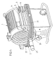
- Fig. 1 shows a perspective view of a headlight with a headlight housing 1, which is composed of a lamp housing 10 and a functional housing 13 with a front cover 11 and a rear cover 12.
- the front cover 11 is connected to a lens frame 14, which contains claws for receiving attachment elements such as diffusers, filter disks, protective disks, swing gate, color changer, shutter and the like, and is connected to the lamp housing 10 via a hinge and a tensioning device 15.
- a bracket 2 To connect the headlamp with a tripod to the stationary arrangement of the headlamp or a rig for suspension of the headlamp a bracket 2 is provided, the two of Fig. 4 two arms 21, 22, a connecting arms 20, 22 connecting arm 20 and a centrally on Connecting arm 20 arranged connecting pin 23 has.
- the ends of the hanger arms 21, 22 are connected to Bügelanlenk Institute 3 arranged diametrically opposite one another on the headlight housing 1 or lamp housing 10.
- the Bügelanschitch 3 consist of a connected to the headlight housing 1 housing rail 4 and connected to the ends of the hanger arms 21, 22 bracket bearing 6, which is positively connected to the housing rail 4 and in the longitudinal direction, that is in the direction of the optical axis of the headlamp on the Housing rail 4 adjustable and in selected positions form and / or non-positively connected to the housing rail 4 is connected.
- the housing rail 4 includes two extending longitudinally of the headlight housing 1 longitudinal grooves 41, 42, which are arranged spaced from each other in the circumferential direction of the headlight housing 1. Between the longitudinal grooves 41, 42 is a sword 40 perpendicular from the housing rail 4 and the headlight housing 1 or lamp housing 10 and has a longitudinal slot 43 which extends over a substantial part of the length of the headlight housing 1 and through the one with the bracket bearing 6 connected locking pin 5 for additional guidance and for positive and / or non-positive determination of the bracket bearing 6 engages.
- the connection between the housing rail 4 and the bow bearing 6 can be solved and the bow bearing 6 can be changed to change the position of the Bügelanlenkung 3 with respect to the longitudinal direction of the headlight housing 1.
- an adjustment of the bracket bearing 6 on the housing rail 4 is again a positive and / or non-positive locking of the bracket bearing 6 with the housing rail 4.
- various center of gravity displacements of the bow linkage 3 can be made to achieve an optimal weight distribution of the headlight with respect to a tripod or a suspension depending on the attached to the attachment part 14 attachment elements.
- the housing rail 4 can either be formed as a profiled part of the headlight housing 1 or the lamp housing 10 or connected as an additional part to the headlight housing 1. If the housing rail 4 is formed as an additional part, it is preferable to provide a screw or plug connection between the front cover 11 and the rear cover 12, which is covered by the lens frame 14 in the region of the front cover 11.
- the back cover 12 may have positive locking elements into which a front side of the housing rail 4 is inserted, while in the front cover 11 holes are provided which are aligned with threaded holes on the front end side of the housing rail 4, so that the housing rail 4 are screwed to the front cover 11 can.
- a double-sided screw the housing rail 4 with the front cover 11 and the back cover 12 by means of screws 16, 17 as shown in FIG. 5 is possible.
- the sword 40 can be inserted into a longitudinal groove of the headlight housing 1 and, for example, by two front side Screws are connected to the front cover 11 and thus fixed to the headlight housing 1.
- FIG. 2 shows an enlarged detail view of the bow linkage 3 according to FIG. 1 with the bow bearing 6 which can be adjusted in the longitudinal direction of the optical axis of the headlight in accordance with the double arrow A on the housing rail 4.
- the bow bearing 6 consists of a bow bearing plate 60, from which two bow bearing arms 64, 65 protrude in the direction of the housing rail 4 or the headlight housing 1 and at their ends with bow bearing webs 61, 62 into the longitudinal grooves 41, 42 engage the housing rail 4, wherein the bracket support webs 61, 62 are angled towards the bottom of the headlamp.
- a bore for receiving the locking pin 5 is arranged, which engages through the longitudinal slot 43 of the vertically projecting from the housing rail 4 sword 40.
- the tensioning device 8 has a tensioning lever 81, a clamping axis 80 engaging through the bow bearing 6 and a disk 83.
- Fig. 3 shows in a longitudinal section through the Bügelanlenkung 3, the connection between the bow bearing 6 and the housing rail 4 and the arrangement and design of the locking pin 5 and its connection to the sword 40 of the housing rail.
- the protruding from the bracket bearing plate 60 of the strap bearing 6 in the direction of the housing rail 4 upper and lower bracket bearing arms 64, 65 have in the longitudinal grooves 41, 42 of the housing rail engaging bracket support webs 61, 62, whose ends are crowned and in hollow cylindrical sections of the longitudinal grooves 41st , 42 intervene.
- This positive connection between the convex bracket bearing webs 61, 62 and the hollow cylindrical longitudinal grooves 41, 42 is a captive connection between the bow bearing 6 and the housing rail 4 and the corresponding part of the headlight housing 1 made.
- the bow bearing 6 is inserted from one of the end faces of the headlight housing in the housing rail 4 and connected by attaching the front cover 11 and the back cover 12 captive with the headlight housing 1.
- the locking pin 5 is inserted through a bore 66 in the upper bow bearing arm 64, engages through the longitudinal slot 43 of the sword 40 and through a bore 67 in the lower bow bearing arm 65.
- a cone 52 In its through the longitudinal slot 43 of the sword 40 cross-section center portion of the locking pin 5 is a cone 52, the shape of which coincides with a plurality of cone openings 44 distributed in the longitudinal direction of the longitudinal slot 43 of the sword 40.
- a compression spring 7 is arranged, which presses the cone 52 against the sword 40 or in one of the cone openings 44.
- the locking pin 5 is pressed against the bias of the compression spring 70 and thus the cone 52 is brought out of engagement with the respective cone opening 44 in the sword 40.
- the bracket bearing 6 By subsequent displacement of the bracket bearing 6 on the housing rail 4 is a shift of emphasis of the headlamp housing 1 shown in FIG. 1 until the cone 52 of the locking pin 5 engages in a cone opening 44 in the sword 40 under the action of spring preload.
- the locking pin 5 has a screw head 51 or is connected to a clamping lever 54 shown in dashed lines, which protrudes from the upper bracket bearing arm 64 for easy accessibility. At its projecting through the lower bracket support arm 65 end of the locking pin 5 is provided with a thread on which a clamping nut 53 is screwed. By screwing the locking pin 5 with the clamping nut 53 of the upper and lower bracket bearing arm 64, 65 are braced against each other and Thus, a frictional connection between the bracket bearing 6 and the Bügelanlenkung 3 and the housing rail 4 and the headlight housing 1 ago.
- the provided for tilt adjustment of the headlight housing 1 relative to the bracket 2 clamping device 8 is composed of a clamping lever 81 shown in FIG. 2 or in Fig. 3 81 ', a cross through the bow bearing 6 clamping axis 80 and a longitudinally slotted box section 63rd the clamping ring 6 used clamping element in the form of a clamping nut 82 together, which is screwed onto a threaded portion of the clamping axis 80.
- the clamping device 8 on a disc brake device in which, for example, the bow bearing 6 is connected to a brake disc, while the tensioning device 8 preferably on the periphery of the brake disc engaging brake pads, the brake disc frictional and because of the Lock the lever arm with high clamping force in any position.
- a quasi-continuous adjustment of the Bügelanlenkung 3 can be made by adjacent cone openings 44 in the longitudinal slot 43 of the sword 40 and thus allow arbitrary fine-stage longitudinal adjustment of the Bügelanlenkung 3 depending on the number and weight of the attachment elements.
- At least one transport position for the bracket 2 in which he claimed a minimum space.
- Such a transport position is shown in perspective in Fig. 4 and shows the displaced to the rear end of the headlight housing 1 Bügelanlenkung 3 with the displaced to the end of the housing rail 4 bracket bearing 6 and engaging in a positive recess of the sword 40 of the housing rail 4 locking pin. 5
- FIG. 5 shows in a perspective view of a headlight housing 1 with a bracket 2 one of the possible connection variants between the housing rail 4 and the headlight housing 1.
- the housing rail 4 is inserted into a positive rail receptacle in the front cover 11 of the headlight housing 1 and after placing the back cover 12 secured by screw 16, 17.
- the screw connections 16, 17 can simultaneously establish a connection between the rear cover 12 and the lamp housing 10.
- the sword 40 is inserted into a longitudinal groove of the lamp housing 10, for example, from the back of the headlight housing 1, and inserted into a positive reception of the front cover 11. After placing the back cover 12 on the lamp housing 10, a connection between the sword 40 and the back cover 12 or the headlight housing 1 is produced by means of the screw 16, 17.
- a screw connection can also be provided there analogous to the screw connections 16, 17 in the rear cover, which is covered by the lens frame 14.
Landscapes
- Engineering & Computer Science (AREA)
- General Engineering & Computer Science (AREA)
- Lighting Device Outwards From Vehicle And Optical Signal (AREA)
Applications Claiming Priority (1)
| Application Number | Priority Date | Filing Date | Title |
|---|---|---|---|
| DE200520013243 DE202005013243U1 (de) | 2005-08-18 | 2005-08-18 | Vorrichtung zum Verbinden eines Scheinwerfers mit einem Bügel |
Publications (2)
| Publication Number | Publication Date |
|---|---|
| EP1754934A1 true EP1754934A1 (fr) | 2007-02-21 |
| EP1754934B1 EP1754934B1 (fr) | 2009-02-25 |
Family
ID=35404849
Family Applications (1)
| Application Number | Title | Priority Date | Filing Date |
|---|---|---|---|
| EP20060017226 Not-in-force EP1754934B1 (fr) | 2005-08-18 | 2006-08-18 | Dispositif pour fixer un projecteur sur un étrier |
Country Status (2)
| Country | Link |
|---|---|
| EP (1) | EP1754934B1 (fr) |
| DE (2) | DE202005013243U1 (fr) |
Citations (5)
| Publication number | Priority date | Publication date | Assignee | Title |
|---|---|---|---|---|
| US4729078A (en) * | 1987-04-27 | 1988-03-01 | Maer Skegin | Extruded lamp housings |
| DE8804591U1 (de) * | 1988-04-07 | 1989-01-12 | Bensabbat, Elie, 6200 Wiesbaden | Vorrichtung zum Verstellen eines Lampenreflektors |
| DE3918699A1 (de) * | 1989-06-08 | 1989-10-26 | Letzel Stephan | Verstellbare haltevorrichtung fuer niedervoltleuchten |
| EP0508157A2 (fr) | 1991-04-09 | 1992-10-14 | ERCO Leuchten GmbH | Projecteur d'éclairage |
| US5548500A (en) * | 1995-07-14 | 1996-08-20 | Mackay; Iain N. B. | Lamp fixture with adjustable lamp socket |
-
2005
- 2005-08-18 DE DE200520013243 patent/DE202005013243U1/de not_active Expired - Lifetime
-
2006
- 2006-08-18 DE DE200650002928 patent/DE502006002928D1/de active Active
- 2006-08-18 EP EP20060017226 patent/EP1754934B1/fr not_active Not-in-force
Patent Citations (5)
| Publication number | Priority date | Publication date | Assignee | Title |
|---|---|---|---|---|
| US4729078A (en) * | 1987-04-27 | 1988-03-01 | Maer Skegin | Extruded lamp housings |
| DE8804591U1 (de) * | 1988-04-07 | 1989-01-12 | Bensabbat, Elie, 6200 Wiesbaden | Vorrichtung zum Verstellen eines Lampenreflektors |
| DE3918699A1 (de) * | 1989-06-08 | 1989-10-26 | Letzel Stephan | Verstellbare haltevorrichtung fuer niedervoltleuchten |
| EP0508157A2 (fr) | 1991-04-09 | 1992-10-14 | ERCO Leuchten GmbH | Projecteur d'éclairage |
| US5548500A (en) * | 1995-07-14 | 1996-08-20 | Mackay; Iain N. B. | Lamp fixture with adjustable lamp socket |
Also Published As
| Publication number | Publication date |
|---|---|
| DE502006002928D1 (de) | 2009-04-09 |
| DE202005013243U1 (de) | 2005-11-10 |
| EP1754934B1 (fr) | 2009-02-25 |
Similar Documents
| Publication | Publication Date | Title |
|---|---|---|
| EP1688696B1 (fr) | Plaque d'épaulement ajustable pour arme à feu de main | |
| EP1613890B1 (fr) | Pied | |
| DE9204927U1 (de) | Vorrichtung zum Einrichten eines Visiers | |
| DE2457935B2 (de) | Kippvorrichtung für ein Gerät, insbesondere für eine Fernsehkamera | |
| DE8805679U1 (de) | Tisch mit höhenverstellbarer und kippbarer Tischplatte | |
| DE2952660C2 (de) | Vorrichtung zum Ausgleich von Drehmomenten | |
| DE9304023U1 (de) | In der Höhe stufenlos verstellbare Haltevorrichtung für Geräte, insbesondere Videoanlagen | |
| EP1483529A1 (fr) | Bras articule, en particulier pour un appareil destine a la prise de vues optique d'objets | |
| DE3903971C1 (fr) | ||
| EP2260235A2 (fr) | Projecteur | |
| EP1754934B1 (fr) | Dispositif pour fixer un projecteur sur un étrier | |
| EP0508157B1 (fr) | Projecteur d'éclairage | |
| AT402857B (de) | Montagevorrichtung für ein zielfernrohr an einem gewehr | |
| EP1085257B1 (fr) | Projecteur d'éclairage avec verrouillage de l'articulation | |
| EP0040180A1 (fr) | Tréteau de montage | |
| EP0392570B1 (fr) | Charnière | |
| DE3319414C2 (de) | Prüfgerät für Fahrzeugscheinwerfer | |
| DE202005015445U1 (de) | Montagevorrichtung zur Befestigung einer Zieleinrichtung auf einer Handfeuerwaffe | |
| DE102016217111A1 (de) | Dachträgervorrichtung | |
| CH693315A5 (de) | Leuchte und Leuchtenanordnung mit mindestens zwei Leuchten. | |
| DE202005013537U1 (de) | Kufenvorrichtung für Beleuchtungsscheinwerfer | |
| DE19619739C1 (de) | Vorrichtung zur Höhenverstellung einer Auflagefläche, insbesondere zur Höhenverstellung eines Computerbildschirmes | |
| EP2107298A1 (fr) | Lampe suspendue allongée | |
| DE3403898C2 (fr) | ||
| DE8903381U1 (de) | Höhenverstellbare Pendelleuchte |
Legal Events
| Date | Code | Title | Description |
|---|---|---|---|
| PUAI | Public reference made under article 153(3) epc to a published international application that has entered the european phase |
Free format text: ORIGINAL CODE: 0009012 |
|
| AK | Designated contracting states |
Kind code of ref document: A1 Designated state(s): AT BE BG CH CY CZ DE DK EE ES FI FR GB GR HU IE IS IT LI LT LU LV MC NL PL PT RO SE SI SK TR |
|
| AX | Request for extension of the european patent |
Extension state: AL BA HR MK YU |
|
| 17P | Request for examination filed |
Effective date: 20070821 |
|
| AKX | Designation fees paid |
Designated state(s): DE FR GB IT |
|
| GRAP | Despatch of communication of intention to grant a patent |
Free format text: ORIGINAL CODE: EPIDOSNIGR1 |
|
| RIN1 | Information on inventor provided before grant (corrected) |
Inventor name: STEGMAIER, KLAUS |
|
| GRAS | Grant fee paid |
Free format text: ORIGINAL CODE: EPIDOSNIGR3 |
|
| GRAA | (expected) grant |
Free format text: ORIGINAL CODE: 0009210 |
|
| AK | Designated contracting states |
Kind code of ref document: B1 Designated state(s): DE FR GB IT |
|
| REG | Reference to a national code |
Ref country code: GB Ref legal event code: FG4D Free format text: NOT ENGLISH |
|
| REF | Corresponds to: |
Ref document number: 502006002928 Country of ref document: DE Date of ref document: 20090409 Kind code of ref document: P |
|
| PLBE | No opposition filed within time limit |
Free format text: ORIGINAL CODE: 0009261 |
|
| STAA | Information on the status of an ep patent application or granted ep patent |
Free format text: STATUS: NO OPPOSITION FILED WITHIN TIME LIMIT |
|
| 26N | No opposition filed |
Effective date: 20091126 |
|
| REG | Reference to a national code |
Ref country code: FR Ref legal event code: PLFP Year of fee payment: 10 |
|
| PGFP | Annual fee paid to national office [announced via postgrant information from national office to epo] |
Ref country code: DE Payment date: 20150714 Year of fee payment: 10 Ref country code: GB Payment date: 20150824 Year of fee payment: 10 |
|
| PGFP | Annual fee paid to national office [announced via postgrant information from national office to epo] |
Ref country code: FR Payment date: 20150824 Year of fee payment: 10 |
|
| PGFP | Annual fee paid to national office [announced via postgrant information from national office to epo] |
Ref country code: IT Payment date: 20150827 Year of fee payment: 10 |
|
| REG | Reference to a national code |
Ref country code: DE Ref legal event code: R119 Ref document number: 502006002928 Country of ref document: DE |
|
| GBPC | Gb: european patent ceased through non-payment of renewal fee |
Effective date: 20160818 |
|
| REG | Reference to a national code |
Ref country code: FR Ref legal event code: ST Effective date: 20170428 |
|
| PG25 | Lapsed in a contracting state [announced via postgrant information from national office to epo] |
Ref country code: GB Free format text: LAPSE BECAUSE OF NON-PAYMENT OF DUE FEES Effective date: 20160818 Ref country code: DE Free format text: LAPSE BECAUSE OF NON-PAYMENT OF DUE FEES Effective date: 20170301 Ref country code: FR Free format text: LAPSE BECAUSE OF NON-PAYMENT OF DUE FEES Effective date: 20160831 |
|
| PG25 | Lapsed in a contracting state [announced via postgrant information from national office to epo] |
Ref country code: IT Free format text: LAPSE BECAUSE OF NON-PAYMENT OF DUE FEES Effective date: 20160818 |