EP1755334A2 - Minimierung der Videostörung während Schaltürbergänge und Signalabwesenheit - Google Patents
Minimierung der Videostörung während Schaltürbergänge und Signalabwesenheit Download PDFInfo
- Publication number
- EP1755334A2 EP1755334A2 EP06125577A EP06125577A EP1755334A2 EP 1755334 A2 EP1755334 A2 EP 1755334A2 EP 06125577 A EP06125577 A EP 06125577A EP 06125577 A EP06125577 A EP 06125577A EP 1755334 A2 EP1755334 A2 EP 1755334A2
- Authority
- EP
- European Patent Office
- Prior art keywords
- signal
- video
- signals
- osd
- sync
- Prior art date
- Legal status (The legal status is an assumption and is not a legal conclusion. Google has not performed a legal analysis and makes no representation as to the accuracy of the status listed.)
- Withdrawn
Links
Images



Classifications
-
- H—ELECTRICITY
- H04—ELECTRIC COMMUNICATION TECHNIQUE
- H04N—PICTORIAL COMMUNICATION, e.g. TELEVISION
- H04N5/00—Details of television systems
- H04N5/44—Receiver circuitry for the reception of television signals according to analogue transmission standards
- H04N5/50—Tuning indicators; Automatic tuning control
-
- H—ELECTRICITY
- H04—ELECTRIC COMMUNICATION TECHNIQUE
- H04N—PICTORIAL COMMUNICATION, e.g. TELEVISION
- H04N21/00—Selective content distribution, e.g. interactive television or video on demand [VOD]
- H04N21/40—Client devices specifically adapted for the reception of or interaction with content, e.g. set-top-box [STB]; Operations thereof
- H04N21/43—Processing of content or additional data, e.g. demultiplexing additional data from a digital video stream; Elementary client operations, e.g. monitoring of home network or synchronising decoder's clock; Client middleware
- H04N21/4302—Content synchronisation processes, e.g. decoder synchronisation
-
- H—ELECTRICITY
- H04—ELECTRIC COMMUNICATION TECHNIQUE
- H04N—PICTORIAL COMMUNICATION, e.g. TELEVISION
- H04N21/00—Selective content distribution, e.g. interactive television or video on demand [VOD]
- H04N21/40—Client devices specifically adapted for the reception of or interaction with content, e.g. set-top-box [STB]; Operations thereof
- H04N21/43—Processing of content or additional data, e.g. demultiplexing additional data from a digital video stream; Elementary client operations, e.g. monitoring of home network or synchronising decoder's clock; Client middleware
- H04N21/431—Generation of visual interfaces for content selection or interaction; Content or additional data rendering
-
- H—ELECTRICITY
- H04—ELECTRIC COMMUNICATION TECHNIQUE
- H04N—PICTORIAL COMMUNICATION, e.g. TELEVISION
- H04N21/00—Selective content distribution, e.g. interactive television or video on demand [VOD]
- H04N21/40—Client devices specifically adapted for the reception of or interaction with content, e.g. set-top-box [STB]; Operations thereof
- H04N21/43—Processing of content or additional data, e.g. demultiplexing additional data from a digital video stream; Elementary client operations, e.g. monitoring of home network or synchronising decoder's clock; Client middleware
- H04N21/438—Interfacing the downstream path of the transmission network originating from a server, e.g. retrieving encoded video stream packets from an IP network
- H04N21/4383—Accessing a communication channel
-
- H—ELECTRICITY
- H04—ELECTRIC COMMUNICATION TECHNIQUE
- H04N—PICTORIAL COMMUNICATION, e.g. TELEVISION
- H04N21/00—Selective content distribution, e.g. interactive television or video on demand [VOD]
- H04N21/40—Client devices specifically adapted for the reception of or interaction with content, e.g. set-top-box [STB]; Operations thereof
- H04N21/45—Management operations performed by the client for facilitating the reception of or the interaction with the content or administrating data related to the end-user or to the client device itself, e.g. learning user preferences for recommending movies, resolving scheduling conflicts
- H04N21/462—Content or additional data management e.g. creating a master electronic programme guide from data received from the Internet and a Head-end or controlling the complexity of a video stream by scaling the resolution or bit-rate based on the client capabilities
- H04N21/4622—Retrieving content or additional data from different sources, e.g. from a broadcast channel and the Internet
-
- H—ELECTRICITY
- H04—ELECTRIC COMMUNICATION TECHNIQUE
- H04N—PICTORIAL COMMUNICATION, e.g. TELEVISION
- H04N21/00—Selective content distribution, e.g. interactive television or video on demand [VOD]
- H04N21/40—Client devices specifically adapted for the reception of or interaction with content, e.g. set-top-box [STB]; Operations thereof
- H04N21/47—End-user applications
- H04N21/482—End-user interface for programme selection
-
- H—ELECTRICITY
- H04—ELECTRIC COMMUNICATION TECHNIQUE
- H04N—PICTORIAL COMMUNICATION, e.g. TELEVISION
- H04N5/00—Details of television systems
- H04N5/44—Receiver circuitry for the reception of television signals according to analogue transmission standards
- H04N5/445—Receiver circuitry for the reception of television signals according to analogue transmission standards for displaying additional information
- H04N5/44504—Circuit details of the additional information generator, e.g. details of the character or graphics signal generator, overlay mixing circuits
-
- H—ELECTRICITY
- H04—ELECTRIC COMMUNICATION TECHNIQUE
- H04N—PICTORIAL COMMUNICATION, e.g. TELEVISION
- H04N21/00—Selective content distribution, e.g. interactive television or video on demand [VOD]
- H04N21/40—Client devices specifically adapted for the reception of or interaction with content, e.g. set-top-box [STB]; Operations thereof
- H04N21/43—Processing of content or additional data, e.g. demultiplexing additional data from a digital video stream; Elementary client operations, e.g. monitoring of home network or synchronising decoder's clock; Client middleware
- H04N21/431—Generation of visual interfaces for content selection or interaction; Content or additional data rendering
- H04N21/4312—Generation of visual interfaces for content selection or interaction; Content or additional data rendering involving specific graphical features, e.g. screen layout, special fonts or colors, blinking icons, highlights or animations
- H04N21/4316—Generation of visual interfaces for content selection or interaction; Content or additional data rendering involving specific graphical features, e.g. screen layout, special fonts or colors, blinking icons, highlights or animations for displaying supplemental content in a region of the screen, e.g. an advertisement in a separate window
Definitions
- This invention relates to a video display operable with standard and high definition television signals and in particular to arrangements for mitigating display disturbances during transient disturbances.
- an on-screen-display based TV Guide provides a list of available channels, and by use of a cursor, the list can be browsed up or down whilst monitoring a preview of the channel in a 119 size picture in picture or PIP. Once the desired channel is found and highlighted, a single button press clears the Guide and displays a full-screen version of the selected channel.
- the main NTSC path is digitized at 1H and then up-converted to 2H.
- the standard TV Menus that are used to control picture parameters like: Color, Tint, Volume, etc. are generated and are inserted by means of a "2H OSD" function located in a video processing IC which generates 2H RGB outputs for coupling to the picture tube.
- OSD on-screen-display
- the addition of an on-screen-display TV Guide would be achieved at 2H, however use of an available 1H on-screen-display generator IC necessitated on-screen-display (OSD) insertion into the main signal prior to sync separation and analog to digital conversion. Because the display system operates at 2H, a standard 1 H horizontal PLL and vertical countdown system are not available.
- the 1H horizontal and 1H vertical sync signals for the Guide OSD are generated by a digital sync separator in the 1H Video Decoder and analog to digital converter IC.
- the system works properly with the Guide OSD being stably positioned on screen, for example, centered both vertically and horizontally on the screen without any tearing or unwanted motion in the characters.
- horizontal and vertical sync signals generated by the Video Decoder can become erratic and spuriously timed.
- the digital sync separator does not employ a countdown system, the period between verticals is often other than the standard interval of 16.7 mille seconds. As a result, the Guide OSD and PIP preview channel are unstable and essentially unusable.
- the digital sync separator provides a selectable free run mode, however, non-random noise present during the absence of a demodulated signal precluded selection of the free run mode resulting in the generation of erroneous sync signals.
- an input signal is controllably muted, i.e. the video amplitude is reduced to zero, to prevent noise for example, occurring during tuning from falsely triggering the sync separator.
- This muted input is selected whenever a video signal is determined to be absent, for example, on a selected RF channel or video input, or as a consequence of the video being obscured or located "behind" an on-screen-display.
- the on-screen-display is inhibited for approximately 1 field following new channel tuning to allow a sync separator to property lock to the new main video signal.
- the inventive first arrangement prevents an unstable Guide presentation during signal absences.
- the inventive arrangement advantageously provides a second use for a tuning video presence detector which initiates selection of a muted input condition to allow the video decoder to operate successfully in the free run mode and synchronize a stable Guide display.
- a further inventive arrangement is advantageously employed to eliminate or obscure display signal transients occurring during channel changes white displaying the on-screen Guide.
- an interruption can occur in the synchronization of Guide OSD.
- the horizontal and vertical sync separating arrangement is advantageously forced to assume the previously mentioned free-running mode.
- the horizontal and vertical has to be locked to the incoming video.
- the input (or output therefrom) is muted allowing the Video Decoder to free run and thereby allow the generation of a readable Guide display.
- the horizontal and vertical sync signals are relocked to the incoming video. This transition, or lack of synchronism between being locked and unlocked generates unacceptable video transients and perturbations lasting for several seconds.
- a horizontal PLL and countdown circuitry was employed yielding horizontal and vertical signals that were relatively stable during channel changes and thus free running operation of the sync separator was not required.
- the Video Decoder IC employs a digital sync separating arrangement and is without the level of noise immunity provided by a PLL with a vertical to countdown arrangement.
- the overlaying of the OSD on the main video proved to be a problem during a channel change, because when just completed, the incoming video is asynchronous with the previously tuned channel.
- the OSD is locked to the free run frequency and phase of the sync signals from the Video Decoder IC.
- the vertical sync interval of the incoming video may or may not be available to the Video Decoder IC for a considerable time interval. For example, because TV network broadcasters employ extremely accurate and stable reference sync sources the relative drift rates can exceed tens of seconds possibly even minutes before the respective vertical sync signals drift through temporary alignment.
- the second inventive arrangement advantageously utilizes the ability of the digital sync separator to achieve lock in approximately 1 field (16 msec) and in addition by advantageously disabling the FSW (fast switch overlay control) line, phasing or synchronization between the OSD (free running syncs) and the incoming sync wave form is eliminated. Furthermore by momentarily blanking the entire screen using the 2H OSD Blanking when switching from the muted input to the desired input, any display transients or perturbations caused by the Video Decoder locking up are concealed and the time to lock the sync separator is greatly reduced.
- FSW fast switch overlay control
- FIG. 1 presents a block schematic diagram of the video path and control signals in a receiver monitor.
- Integrated circuit U10 is a video input switch or cross point that allows user selection between various video inputs, for example the main tuner 100, second tuner 110, component signal Y Pr Pb, Auxiliary inputs 1-3, etc. Since a cross point video switch is used, any one of the video inputs can be routed simultaneously to any of the outputs.
- Integrated circuit U10 is controlled by 1 2 C bus commands generated by the chassis controller IC U8. For example, when the main tuner video (OAM) is selected by IC U10, the received demodulated signal is buffered and supplied to IC U12, the picture in picture processor F2PIP, as a composite video signal, MAIN CV.
- OAM main tuner video
- a second buffered output from switch IC U10, picture in picture composite video, PIP CV is coupled to IC U12.
- the F2PIP processor digitizes both the MAIN-CV and the PIP_CV signals and appropriately inserts the PIP signal into the MAIN-CV signal.
- the outputs from the FPIP digital to analog converters are analog YC component signals, MAIN Y/C which is coupled to the 1H portion of IC U1, the Input Processor.
- the Luminance component of signal MAIN Y/C is output from IC U1 as signal INT_1HYUV which becomes one two inputs supplied to IC U2, a video overlay switch.
- the fast switch, FSW, Line is activated for most of the active lines on the screen.
- the FSW line is disabled during the vertical sync interval, approximately lines 1 - 9, and during the horizontal sync period (see Figure 5).
- the combined signal output, Y Pr Pb, from IC s U2 is coupled for analog to digital conversion by Video Decoder IC U3, which produces a digital output word "11-1 DO-D7".
- IC U3 includes a digital sync separator which produces analog horizontal sync (HSYNC or H-656) and vertical sync (VSYNC or Vs 656) signals derived from the luminance component. These separated sync signals are used to synchronize the Guide on screen display to the incoming video. Both the digitized video and the horizontal and vertical sync signals are coupled to De-Interlacer IC U4. The De-Interlacer IC provides upconversion of the digitized 1 H signal to produce a 2H frequency digital display signal which is D/A converted to form output signal 2H VIDEO. This upconverted signal is coupled to the 2H portion of IC U1 for matrix processing to form red green is and blue, RGB_OUT analog video signals for display.
- HSYNC or H-656 analog horizontal sync
- Vs 656 vertical sync
- Figure 2 is a flowchart depicting a portion of an inventive "Main Loop" display software for a periodic testing sequence performed by controller U8.
- the sequence of Figure 2 periodically tests for the presence or absence of a video signal on a selected input. Whether the Guide on screen display (OSD) is present or not, repetitive testing occurs at approximately 500 mille second intervals with the result communicated by controller U8.
- Figure 3 illustrates the operation of the software depending on whether the OSD Guide is present or not. If the Guide is selected, the PIP is turned off, the muted input is selected, for example by switch Q1 responsive to GPIB#1, causing the Video Decoder sync separator to free run.
- OSD Guide on screen display
- the chassis controller or main micro U8 will detect that video is absent.
- the main micro detects the "no video” condition by monitoring the Tuning Sync signal with a hardware detector coupled to the main tuner output for use during channel tuning.
- the "video presence detector” in micro U8 counts the number of nominally standard width horizontal sync pulses occurring during each field. If an "error count" exceeds a predetermined limit, a data bit is flipped to indicate that video is absent.
- This sync presence detector is advantageously software controlled to repetitively sample the selected video every 500 mine seconds.
- microcontroller U8 When a "no video" condition is detected, (for example as shown in Figure 3), the main micro advantageously turns off the PIP to eliminate edge noise in the display.
- microcontroller U8 outputs an I z C bus command which is decoded by IC to U11 to form signal GPIO#2 which mutes or blanks the second tuner 110 output OAP to input selector switch IC U2. Input blanking is achieved by transistor Q2 which is saturated by the decoded control signal GPIO#2. In this way chassis microcontroller U8 asserts a free run condition in Video Decoder U3 and waits for the monitoring loop depicted in Figure 2 to signal the reappearance of a tuning Sync Signal by testing YES at the video present decision diamond.
- micro U8 When a video signal is subsequently detected, micro U8 generates a blanking signal (2H OSD Blanking) which momentarily blanks the 2H analog RGB display signals, coincidentally Input Switch U10 is switched back to the Main Tuner output to facilitate locking of Video Decoder U3, and PIP is enabled and finally the screen is unblanked by signal 2H OSD Blanking.
- Figure 3 also outlines the operation of the "no signal" condition when the Guide is not selected. Since the Tuning Sync detector (U4) associated with the Main Micro U8 monitors only the output (OAM) from the main tuner output, separate video presence detectors resident within U12 are employed for the 2nd tuner output (OAP) or PIP video feed.
- video presence detectors within U12 are supplied with signals from various other inputs to input switch U10 responsive to selective control by controller U8. These input signals, though not selected for immediate display are coupled to inputs SEL. Ipx, and SEL. Ipy of IC U12 and are monitored for the presence of specific signals, for example, component video, YIC video or NTSC video in order that optimum picture quality can be automatically selected and displayed when there is a choice of different format signal sources. Thus a total of five different detectors are employed to monitor the presence of the various input signals.
- the main tuner output can be muted by GPIO#1 during signal absence, such muting prevents verification of channel acquisition during tuning.
- the video image in the PIP (which is part of the Guide) comprises random noise since both the main video (OAM) and PIP video (OAP) paths are muted, the preview PIP is blanked.
- the muted input is routed to the sync separator which responds by entering a free run mode that generates stable horizontal and vertical sync.
- These stable sync signals facilitate the generation of a stable, readable on-screen-display during input signal absence.
- the determination of valid video presence is performed by a tuning sync "video presence detector" which is monitored when the main tuner video is selected.
- the synchronization deficiencies described previously can also occur with signal absence at any input, for example main tuner, 2nd tuner, aux 1, aux 2, aux 3, component inputs, etc.
- the advantageous video presence detector arrangement is beneficially employed to detect signal absence at any input.
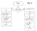
- Figure 7 illustrates the channel tuning process both with and without a video signal present on the channel or video input, and it assumes that the Guide is selected. Tuning is initialed at block 71 of Figure 7. To prevent noise present in the box surrounding the PIP, the PIP is turned off at block 72 during tuning from within the Guide. The Video Input Switch U10 is changed to the "muted input" condition at block 73, for example the 2nd tuner video Figure 1. Once the video signal into the Video Decoder is muted that is nominally flat, random noise, the Video Decoder switches to a free-run mode at block 74, via an I 2 C bus command from micro U8.
- an 1 2 C command disables or inhibits Sync Clipping at block 75, which allows amplified or stretched amplitude sync pulses to be present later in the tuning process while the Video Decoder is attempting to lock, and sync separate signals from the newly selected / found channel.
- a standard +/- 2MHz channel search is performed using the main tuner. This channel search allows for offset air (MAN) or cable channels to be properly tuned. The new channel is acquired at block 77, however, if a channel is not present the tuning system defaults to FCC Nominal channel frequencies.
- the video presence detector is tested for the presence or absence of the selected input, with the result, YES signaled at block 79, or NO signaled at block 80.
- block 79 tests YES, video is present, the sequence continues at block 81, with screen blanking occurring, at block 82, by use of 2H OSD in IC U1. Activating 2H OSD blanking obscures any unwanted transient video effects from being coupled for display as the sync separator in the Video Decoder U3 is locking.
- the fast switch is disabled, FSW Disable, via a general purpose output, GPIO, decoded from the 12C bus by IC U4. This FSW Disable signal saturates Q3 which disables the FSW line from U13, the Gemstar TM OSD generator and consequently inhibits OSD insertion or addition by IC U2.
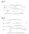
- Figures 5 and 6 are helpful in understanding the affects of disabling the FSW tine.
- Figure 5 shows waveforms A, B and C.
- Waveform A illustrates the presence of the Guide OSD for approximately 220 of the 262.5 horizontal lines in a field.
- Waveform B shows the time relationship between Vertical Sync and the Guide OSD.
- Waveform C depicts the Vertical sync pulse interval with a, b and c representing the pre-equalization pulses, vertical sync pulses, and the postequalization pulses respectively.
- the Guide OSD which is overlaid on the active video, is not active or present during the Vertical interval.
- the vertical interval is the most significant hence it only will be described.
- the vertical sync interval comprising elements a, b and c is present in the luminance signal supplied the Video Decoder U3.
- the digital sync separator within IC U3 separates the Vertical and Horizontal sync pulses and generates output signals HSYNC and VSYNC which are coupled to synchronize OSD generation in the Guide IC U12.
- FIG. 6A shows the Guide OSD which is active for approximately 220 of the 262.5 horizontal lines of an SD or 1H field. Since the Guide OSD and the incoming video signal are asynchronous, and the Guide is present for about 220 of the 262.5 tines per field, it could take considerable time for the vertical sync interval to drift into synchronism with the Guide OSD vertical sync and then be detected.
- Waveform 6B shows the random Vertical Sync that may occur since the Video Decoder is not locked.
- Waveform 6C shows the luminance signal coupled for sync separation by the Video Decoder with the Guide OSD obscuring, or blanking the vertical sync interval of the newly acquired video signal.
- Waveform D shows the newly tuned video with the Guide OSD temporarily removed or inhibited by activating FSW Defeat as depicted at block 83 of FIGURE 7.
- Video not Present When video is absent the Video Decoder is maintained in the free run state at block 92, as employed during the tuning process. In order for the Video Decoder to properly function in the free run condition, the "muted input" mode is selected at block 93 and the Sync Clipper is enabled at block 94 to prevent video level shifts resulting from sync amplitude AGC. At block 95 the control sequence returns to the main loop.
- the inventive arrangement employs a "FSW Control" or disable line to temporarily inhibit Guide insertion.
- This control signal FSW Control is generated responsive to an 1 2 C bus command and decoded by a general purpose input output port (GPIO) of IC U4.
- the Guide OSD is disabled for approximately 60 mine seconds following the signaled completion of tuning.
- This advantageous control capability ensures that the sync separator in the Video Decoder IC wilt capture the vertical sync block at lines 1-9 of the NTSC Video and generate the proper horizontal and vertical sync to lock the Guide OSD.
- the inventive momentarily inhibition of the Guide OSD following channel tuning facilitates vertical sync separation of the new signal by Video Decoder.
Landscapes
- Engineering & Computer Science (AREA)
- Multimedia (AREA)
- Signal Processing (AREA)
- Databases & Information Systems (AREA)
- Human Computer Interaction (AREA)
- Computer Graphics (AREA)
- Studio Circuits (AREA)
- Two-Way Televisions, Distribution Of Moving Picture Or The Like (AREA)
Applications Claiming Priority (2)
| Application Number | Priority Date | Filing Date | Title |
|---|---|---|---|
| US32209701P | 2001-09-14 | 2001-09-14 | |
| EP02292125A EP1294187A3 (de) | 2001-09-14 | 2002-08-29 | MInimierung der Videostörung während Schalttransienten und Signalabwesenheit |
Related Parent Applications (1)
| Application Number | Title | Priority Date | Filing Date |
|---|---|---|---|
| EP02292125A Division EP1294187A3 (de) | 2001-09-14 | 2002-08-29 | MInimierung der Videostörung während Schalttransienten und Signalabwesenheit |
Publications (2)
| Publication Number | Publication Date |
|---|---|
| EP1755334A2 true EP1755334A2 (de) | 2007-02-21 |
| EP1755334A3 EP1755334A3 (de) | 2008-06-18 |
Family
ID=37648625
Family Applications (1)
| Application Number | Title | Priority Date | Filing Date |
|---|---|---|---|
| EP06125577A Withdrawn EP1755334A3 (de) | 2001-09-14 | 2002-08-29 | Minimierung der Videostörung während Schaltürbergänge und Signalabwesenheit |
Country Status (1)
| Country | Link |
|---|---|
| EP (1) | EP1755334A3 (de) |
Family Cites Families (3)
| Publication number | Priority date | Publication date | Assignee | Title |
|---|---|---|---|---|
| IT1099331B (it) * | 1977-09-26 | 1985-09-18 | Philips Nv | Complesso ricevitore per televisione |
| US4677484A (en) * | 1985-05-10 | 1987-06-30 | Rca Corporation | Stabilizing arrangement for on-screen display |
| JP3132539B2 (ja) * | 1994-12-27 | 2001-02-05 | ソニー株式会社 | デジタル放送番組切換装置および方法 |
-
2002
- 2002-08-29 EP EP06125577A patent/EP1755334A3/de not_active Withdrawn
Also Published As
| Publication number | Publication date |
|---|---|
| EP1755334A3 (de) | 2008-06-18 |
Similar Documents
| Publication | Publication Date | Title |
|---|---|---|
| KR100940749B1 (ko) | 보조 정보를 처리하는 능력을 갖는 비디오 신호 처리 시스템 | |
| EP0945004B1 (de) | Videosignalverarbeitungsgerät zur veränderung unabhängiger bilder in einer mehrfachbildanzeige | |
| JPH1023377A (ja) | テレビジョン受信機を利用したテキストデータ処理装置 | |
| US6982765B2 (en) | Minimizing video disturbance during switching transients and signal absence | |
| KR19990071821A (ko) | 텔레비전수상기,수신채널을세트하는방법및화상표시방법 | |
| US6587153B1 (en) | Display apparatus | |
| EP1497978B1 (de) | Zusatzsignalsynchronisierung für untertiteleinblendung | |
| EP1755334A2 (de) | Minimierung der Videostörung während Schaltürbergänge und Signalabwesenheit | |
| KR100747499B1 (ko) | 영상처리장치 및 영상처리방법 | |
| KR100331834B1 (ko) | 티브이의 epg 구현장치 및 방법 | |
| JP2001028718A (ja) | 表示言語自動切換装置 | |
| JP3316271B2 (ja) | テレビジョン受像機 | |
| KR100223783B1 (ko) | 텔레비전의 캡션표시기간 지연처리장치 | |
| JP3055796U (ja) | 映像処理装置 | |
| EP1672924A2 (de) | Anzeigevorrichtung und -verfahren | |
| CN1316815C (zh) | 瞬间信号中断后的信号捕获 | |
| KR100265037B1 (ko) | 텔레비젼의표준신호레벨검출라인발생방법및그장치 | |
| JPH04319883A (ja) | テレビ受像機 | |
| JPH06217221A (ja) | 文字放送受信機 | |
| KR19990042401A (ko) | 텔레비젼에서의 수직 동기 제어 방법 | |
| JP2003507939A (ja) | デジタルチューナ付のピクチャー・イン・ガイドジェネレータ | |
| KR19990042403A (ko) | 멀티스탠다드 텔레비젼에서의 수신할 방송방식 메뉴의 화면표시방법 | |
| KR19990034050A (ko) | 텔레비전에서 pip 두 화면시 언어 자동 절환 방법 | |
| KR20000020429A (ko) | 텔레비젼에서의 osd 문자 크기 자동 조정 방법 | |
| JPH0585172U (ja) | テレビジョン受像機 |
Legal Events
| Date | Code | Title | Description |
|---|---|---|---|
| PUAI | Public reference made under article 153(3) epc to a published international application that has entered the european phase |
Free format text: ORIGINAL CODE: 0009012 |
|
| AC | Divisional application: reference to earlier application |
Ref document number: 1294187 Country of ref document: EP Kind code of ref document: P |
|
| AK | Designated contracting states |
Kind code of ref document: A2 Designated state(s): AT BE BG CH CY CZ DE DK EE ES FI FR GB GR HU IE IS IT LI LT LU LV MC NL PL PT RO SE SI SK TR |
|
| AX | Request for extension of the european patent |
Extension state: AL BA HR MK YU |
|
| PUAL | Search report despatched |
Free format text: ORIGINAL CODE: 0009013 |
|
| AK | Designated contracting states |
Kind code of ref document: A3 Designated state(s): AT BE BG CH CY CZ DE DK EE ES FI FR GB GR HU IE IS IT LI LT LU LV MC NL PL PT RO SE SI SK TR |
|
| AX | Request for extension of the european patent |
Extension state: AL BA HR MK RS |
|
| 17P | Request for examination filed |
Effective date: 20081216 |
|
| AKX | Designation fees paid |
Designated state(s): DE FR GB |
|
| RAP1 | Party data changed (applicant data changed or rights of an application transferred) |
Owner name: THOMSON LICENSING |
|
| 17Q | First examination report despatched |
Effective date: 20101026 |
|
| STAA | Information on the status of an ep patent application or granted ep patent |
Free format text: STATUS: THE APPLICATION IS DEEMED TO BE WITHDRAWN |
|
| 18D | Application deemed to be withdrawn |
Effective date: 20110301 |