EP1755801B2 - Dispositif et procede destines a former et tremper une poutre - Google Patents
Dispositif et procede destines a former et tremper une poutre Download PDFInfo
- Publication number
- EP1755801B2 EP1755801B2 EP05740415.4A EP05740415A EP1755801B2 EP 1755801 B2 EP1755801 B2 EP 1755801B2 EP 05740415 A EP05740415 A EP 05740415A EP 1755801 B2 EP1755801 B2 EP 1755801B2
- Authority
- EP
- European Patent Office
- Prior art keywords
- cooling medium
- opening
- shaping
- collecting
- quenching
- Prior art date
- Legal status (The legal status is an assumption and is not a legal conclusion. Google has not performed a legal analysis and makes no representation as to the accuracy of the status listed.)
- Expired - Lifetime
Links
Images


Classifications
-
- B—PERFORMING OPERATIONS; TRANSPORTING
- B21—MECHANICAL METAL-WORKING WITHOUT ESSENTIALLY REMOVING MATERIAL; PUNCHING METAL
- B21D—WORKING OR PROCESSING OF SHEET METAL OR METAL TUBES, RODS OR PROFILES WITHOUT ESSENTIALLY REMOVING MATERIAL; PUNCHING METAL
- B21D7/00—Bending rods, profiles, or tubes
- B21D7/02—Bending rods, profiles, or tubes over a stationary forming member; by use of a swinging forming member or abutment
- B21D7/024—Bending rods, profiles, or tubes over a stationary forming member; by use of a swinging forming member or abutment by a swinging forming member
- B21D7/028—Bending rods, profiles, or tubes over a stationary forming member; by use of a swinging forming member or abutment by a swinging forming member and altering the profile at the same time, e.g. forming bumpers
-
- C—CHEMISTRY; METALLURGY
- C21—METALLURGY OF IRON
- C21D—MODIFYING THE PHYSICAL STRUCTURE OF FERROUS METALS; GENERAL DEVICES FOR HEAT TREATMENT OF FERROUS OR NON-FERROUS METALS OR ALLOYS; MAKING METAL MALLEABLE, e.g. BY DECARBURISATION OR TEMPERING
- C21D1/00—General methods or devices for heat treatment, e.g. annealing, hardening, quenching or tempering
- C21D1/56—General methods or devices for heat treatment, e.g. annealing, hardening, quenching or tempering characterised by the quenching agents
- C21D1/60—Aqueous agents
-
- C—CHEMISTRY; METALLURGY
- C21—METALLURGY OF IRON
- C21D—MODIFYING THE PHYSICAL STRUCTURE OF FERROUS METALS; GENERAL DEVICES FOR HEAT TREATMENT OF FERROUS OR NON-FERROUS METALS OR ALLOYS; MAKING METAL MALLEABLE, e.g. BY DECARBURISATION OR TEMPERING
- C21D1/00—General methods or devices for heat treatment, e.g. annealing, hardening, quenching or tempering
- C21D1/62—Quenching devices
- C21D1/673—Quenching devices for die quenching
-
- C—CHEMISTRY; METALLURGY
- C21—METALLURGY OF IRON
- C21D—MODIFYING THE PHYSICAL STRUCTURE OF FERROUS METALS; GENERAL DEVICES FOR HEAT TREATMENT OF FERROUS OR NON-FERROUS METALS OR ALLOYS; MAKING METAL MALLEABLE, e.g. BY DECARBURISATION OR TEMPERING
- C21D9/00—Heat treatment, e.g. annealing, hardening, quenching or tempering, adapted for particular articles; Furnaces therefor
- C21D9/0068—Heat treatment, e.g. annealing, hardening, quenching or tempering, adapted for particular articles; Furnaces therefor for particular articles not mentioned below
-
- C—CHEMISTRY; METALLURGY
- C21—METALLURGY OF IRON
- C21D—MODIFYING THE PHYSICAL STRUCTURE OF FERROUS METALS; GENERAL DEVICES FOR HEAT TREATMENT OF FERROUS OR NON-FERROUS METALS OR ALLOYS; MAKING METAL MALLEABLE, e.g. BY DECARBURISATION OR TEMPERING
- C21D9/00—Heat treatment, e.g. annealing, hardening, quenching or tempering, adapted for particular articles; Furnaces therefor
- C21D9/08—Heat treatment, e.g. annealing, hardening, quenching or tempering, adapted for particular articles; Furnaces therefor for tubular bodies or pipes
-
- C—CHEMISTRY; METALLURGY
- C21—METALLURGY OF IRON
- C21D—MODIFYING THE PHYSICAL STRUCTURE OF FERROUS METALS; GENERAL DEVICES FOR HEAT TREATMENT OF FERROUS OR NON-FERROUS METALS OR ALLOYS; MAKING METAL MALLEABLE, e.g. BY DECARBURISATION OR TEMPERING
- C21D9/00—Heat treatment, e.g. annealing, hardening, quenching or tempering, adapted for particular articles; Furnaces therefor
- C21D9/08—Heat treatment, e.g. annealing, hardening, quenching or tempering, adapted for particular articles; Furnaces therefor for tubular bodies or pipes
- C21D9/085—Cooling or quenching
Definitions
- the invention relates to a method and a device for manufacturing a quenched beam.
- the beam is formed of sheet metal and has a closed cross-section. This beam shape has as a result that the bumper takes up and distributes collision forces, torsional loads, strains and other forms of loads in an optimal way.
- the closed section makes the beam voluminous and space consuming and often difficult to apply in the given space in a vehicle body.
- a bumper beam for vehicles where the beam is elongated, has two ends and a closed cross-section.
- the beam sides are divided in a front flange directed forward in the normal direction of movement of the vehicle, a rear flange directed towards the vehicle, an upper web and a lower web.
- At least one portion of the rear flange, running along the beam, is impressed/intended towards at least one portion of the front flange running along the beam.
- the resulting indentation is complete a certain and limited distance from the beam ends and inwardly towards the beam centre portion.
- the inner sides of the portions are in contact with each other and hereby the beam has its greatest volume at its centre part and its smallest volume at the ends along the certain and limited distance.
- a vehicle front is often curved backwards out towards the vehicle sides in order to decrease the air resistance, improve the collision force absorbing properties and make the design appealing.
- This prior art bumper beam has the corresponding curvature in order to optimize the use of space.
- the beam centre portion has a big volume and a big amount of material to be able to provide the best energy absorption possible at a collision.
- the beam is changed as far as shape is concerned in order to simplify the mounting of the beam to the vehicle.
- profile element as it is used in the following, is meant a beam blank in the form at the tube-shaped blank with constant cross-section profile, which is collected from a roll-former plant or a similar sheet metal forming machine, and by the expression beam is meant a beam blank as well as a profile element or beam blank after that shaping and quenching of the same in a shaping tool has been performed.
- the profile element or beam blank is straight when it is heated and fed to the tool arrangement for shaping.
- the profile element or beam blank may be pre-formed cold or hot before it is heated and fed to the tool arrangement for shaping and quenching to a finished beam.
- the blank does not have to be straight and/or does not have to have a constant cross-section along the blank or profile element.
- the tool arrangement has to be adapted accordingly.
- curvature as used here it should be realized that it can be a question of, starting from tube-shaped profile elements, manufacturing hollow beams, which can have both uni- and duo-curved surfaces, ie surfaces which can be curved or shaped in a number of axis directions.
- the object of the method and the device, described below is to provide a method which fulfils this desire and which, more specifically, provides an efficient cooling speed for the quenching independent of the given shape of the beam created.
- Another object of the invention is to provide a device for carrying out the method.
- a curved and quenched hollow beam 21 is shown, which is manufactured starting from a beam-shaped profile element by profilation in a profile mill or roll-former plant.
- a strip or sheet has been used, which has been given the shape of said beam with a closed cross-section and showing a first opening 22 in one end portion 23 and, a second opening 22' in the other end portion 23'.
- the closed cross-section has in a known way been obtained by fixing the strip edges, which after the rollforming meet and abut against each other, to each other by welding, eg by sopt welding, seam welding or the like.
- the beam 21 has been given transverse local indentations 24 and may, even if it is not shown in the Fig., be provided with longitudinal grooves to further improve the beam 21 torsional and bending rigidity.
- the provision of said longitudinal grooves may be of special interest in case of manufacturing bumper beams or body details for vehicles, whereby the longitudinal grooves and the transverse local indentations contribute to the beam 21 chock-absorbing properties. It must be said that the expressions "shaping" and "bending” as used in the following refers to substantially all, to the person skilled in the art known, shaping methods for a hollow profile element to a beam of a desired shape.
- the beam 21 has been bent along the longitudinal axis 25, so that it shows one convex 26 and one concave 27 main side respectively. Further the beam 21 has along the concave main side 27 been given an extensive longitudinal material indentation 28, which is so arranged that the beam shows the highest profile height in the centre portion 29 and the lowest profile height at the end portions 23, 23'.
- On the convex main side of the beam there is arranged a number of longitudinal relatively small profiling grooves 30, which contribute both to the beam rigidity and prevents buckling of the beam.
- profiling grooves 30 reference also to Fig. 4, 5 and 8, 9 is made.
- Figs. 2 and 3 a longitudinal section of a combined shaping and quenching device 31 for the manufacture of the beam according to Fig. 1 is shown.
- Fig. 2 the combined shaping and quenching device 31 in a first state of operation is shown and in Fig. 3 it is shown in a second state of operation.
- the shaping and quenching device 31 comprises support parts 32:1- 32:n, which are mutually movable and which are arranged to supportingly between them receive sections of the profile clement and by manoeuvring relative to each other shape the profile element between them to a beam of desired shape. Since the shaping in this case substantially occurs in a vertical plane only, the support parts are in this case carried by a by 3 designated upper, first tool part and a by 4 designated lower, second, tool part. Operated by set and manoeuvre means 35 in the form of hydraulic cylinders the two tool parts are movable to and from each other and intended to receive and between them shape a profile element, a beam blank, heated to austenitizing temperature to a finished beam 21.
- the upper and the lower tool parts 3, 4 are provided with the above mentioned support parts 32:1 - 32:n having as a task to both shape the pipe-shaped profile element between them to a beam and hold the thus formed beam 21 in the shaping device for a subsequent quenching step.
- Fig. 4 the blank centre portion 29 is shown in cross-section in the starting position before the shaping and seen along the line 4-4 in Fig. 2 and in Fig. 5 the end portion 23 of the beam formed by the shaping is shown in cross-section along the line 5-5 in Fig. 3 .
- a device 31 as described above is one embodiment of a device suitable for application of this second aspect of the present invention.
- the shaping and quenching device 31 comprises means 36 being in close connection with, in the Figs. not shown, source for output of a forced flow of cooling medium and means 37 for receiving and in a controlled way removing of such a cooling medium.
- Said cooling medium preferably consists of water, which is led into the hollow beam 21 via the output means 36 and after having passed through the beam is led out from the beam via the receiving means 37.
- Said output means and receiving means 36, 37 respectively, are located in the lower, second tool part 4 and thereby on the tool part against which the heated profile element 27 main side 26 is intended to be bent to a concave shape.
- the output means 36 comprises a flushing nozzle 38 and the receiving means 37 comprises a collection nozzle 39, which nozzles 38, 39 are so arranged in relation to the finished shaped beam 21 relative position between the tool parts that the beam openings 22, 22' in the end portions 23, 23' are present in a position adjacent or substantially ending against said nozzles 38, 39 ( Fig. 3 ).
- the profile element for the beam 21 is driven or bent so that the first opening 22 in the beam end portion 23 meets and is put into flow transferring connection with the output means 36 flushing nozzle 38.
- the other beam end portion 23' is bent so that the other beam opening 22' meets and is put into flow transferring connection with the collecting means 37, collecting nozzle 39.
- cooling medium may be led in through the beam 21 via the first opening 22 and after passage through the beam, out via the beam other opening 22'.
- the shaping and quenching device comprises a detection means 40, e.g. in the form of a photocell or switch, which may be arranged to detect the tool parts 3, 4 relative positions or, as in this case, be arranged to register the presence of the beam 21 first opening 22 adjacent to the collecting means 37 collecting nozzle 39.
- a fast cooling of the beam 21 is thus provided hereby by leading the cooling medium via the output means into the hollow beam via the opening 22 in one end portion 23 of the beam and by leading the cooling medium out in a controlled way via the collecting means 37 and the opening 22' in the beam 21 other end portion 23' after having passed through the beam 21.
- a shaping and quenching device 31 is shown in a second embodiment, which primarily is intended for shaping or bending of the type of beams 21 having substantially closed or quite limited openings, semi-closed, in the end portions 23, 23', ie beams 21 with limited passage for leading cooling medium out through the respective ends of the beam 21.
- Fig. 8 the centre portion of the blank for a beam 21 is shown in cross-section in a starting position before the shaping and seen along the line 8-8 in Fig.6
- Fig. 9 the manufactured beam 21 end cross-section after the shaping is shown, seen along the line 9-9 in Fig. 7 . Since the design of the upper and lower tool parts 3, 4, comprised by the shaping and quenching device 31, and the support means 32:1 - 32:n comprised therein, substantially totally is determined by the predetermined shape of the beam, these will, as such, not be described in detail for a beam in this design.
- the nozzle in this embodiment is located adjacent to the beam 21 centre portion 29. More specifically, a number of flushing nozzles 38 arranged at angles and at a distance in relation to each other are used, the nozzles are located so that they are present turned to or ending at the main side 27 of the beam the side being concave after the shaping.
- the beam has at the main side 27, having been bent to a concave shape, been provided with holes 41, which serve as a first opening 22 in the beam and also for introduction of cooling medium into the beam. These holes 41 are located so that they during the shaping of the beam are driven to meet and establish flow connections with the, at a distance in relation to each other located, flushing nozzles in the lower tool part. Since the beam ends are substantially closed and allow only a limited discharge of cooling medium, not only one end of the beam is used for discharging of cooling medium but both beam end portions 23, 23'.
- the cooling medium For collecting the cooling medium the cooling medium, which is led out from the beam 21 are, as collecting means 37, two collecting nozzles 39, 39' arranged, one of which is arranged in the area of the first opening 22 in one end portion of the beam and the other in the area of the second opening 22' in the other end portion 23' of the beam.
- the collecting means 37 collecting nozzles 39, 39' are arranged in relation to the beam relative position between the tool parts 3, 4, so that the collecting nozzles 39, 39' are present at a position just in front of or substantially running out against the first and the second opening 22, 22' respectively in the beam ends 23, 23" when the beam is finished. Consequently, flow connections are hereby also established for leading cooling medium out of the beam 21 via said collecting nozzles 39, 39' and the beam first and second 22, 22' openings, only in the finally shaped stage of the beam.
- the detection means 40 which detects the tool parts 3, 4 relative positions or, as in this example, the presence of the finished beam 21 first opening 22, which in this case is formed by the two holes 41, in relation to the output means 36 flushing nozzles 38.
- the detection means also detects the relative presence between the finished beam 21 second opening, in this case defined as the opening in the beam respective ends, and the collecting means 37 two collecting nozzles 39, 39'.
- the holes 41 and consequently also the output means 36 flushing nozzles 38 should be located as near the beam 21 centre portion 29 as possible in case of a symmetric beam.
- the flushing nozzles 38 as well as the corresponding holes arranged in the beam 21 may be distributed in a suitable way along the beam.
- the holes 41 are preferably located in such a way that the cooling medium flow is about the same towards the respective end portions 23, 23' of the beam.
- a preferred, suitable, quenching temperature or to the austenitizing temperature for eg a boron steel about 850-900°C
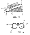
- Fig. 10 and 11 which are not covered by the claims an embodiment of the device is shown, which differs from the above exemplified devices in that the cooling medium exclusively is brought to pass through the beam via one end 23, ie the opening in one beam end portion 23 is used as both a first opening 22 for leading cooling medium into the beam cavity and a second opening 22' for leading the cooling medium out of the beam.
- the opening in this case, double functions are illustrated by the two arrows 45, 46 in Fig. 10 and Fig. 11 .
- Said flushing nozzle 38 and collecting nozzle 39 respectively are so arranged in relation to the beam position between the tool parts 3, 4 that they are present in a position just in front of or substantially running out against the single opening 22 in the beam end portion 23 when the beam is finished.
- the profile element or beam blank does not have to be straight and/or have to have a constant cross-section but may be pre-formed cold or hot to a different shape before being heated, at least after cold pre-forming, and shaped to a finished beam shape and quenched.
Landscapes
- Chemical & Material Sciences (AREA)
- Engineering & Computer Science (AREA)
- Mechanical Engineering (AREA)
- Materials Engineering (AREA)
- Crystallography & Structural Chemistry (AREA)
- Thermal Sciences (AREA)
- Physics & Mathematics (AREA)
- Metallurgy (AREA)
- Organic Chemistry (AREA)
- Bending Of Plates, Rods, And Pipes (AREA)
- Heat Treatment Of Articles (AREA)
- Facsimile Scanning Arrangements (AREA)
- Analysing Materials By The Use Of Radiation (AREA)
Claims (19)
- Procédé pour façonner et tremper des poutres creuses, dans lequel un élément profilé en forme de tuyau, chauffé à une température de trempe et de préférence fabriqué par profilage, est placé dans un dispositif de façonnage muni de pièces de support, qui sont mutuellement déplaçables et qui sont destinées à recevoir entre elles en les supportant des portions de l'élément profilé et qui, en manoeuvrant les unes par rapport aux autres, façonnent l'élément profilé en une poutre de forme souhaitée, et dans lequel la poutre ainsi formée est trempée du fait de sa mise en contact avec un fluide de refroidissement évacuant la chaleur pour l'évacuation de la chaleur, caractérisé en ce que le fluide de refroidissement est amené à passer dans la cavité de la poutre alors que la poutre est encore positionnée dans le dispositif de façonnage.
- Procédé selon la revendication 1, dans lequel le fluide de refroidissement est amené à passer dans la cavité de la poutre via une première (22) et une deuxième (22') ouverture de poutre.
- Procédé selon la revendication 1 ou 2, dans lequel une buse de rinçage (38), en connexion fermée avec une source pour décharger un fluide de refroidissement sous pression, est utilisée pour alimenter la poutre en fluide de refroidissement via une première ouverture de poutre (22).
- Procédé selon la revendication 2 ou 3, dans lequel une buse collectrice (39) pour recevoir et évacuer le fluide de refroidissement est utilisée pour évacuer le fluide de refroidissement hors de la poutre d'une manière contrôlée via la deuxième ouverture (22').
- Procédé selon la revendication 3 ou 4, dans lequel la première ouverture de poutre (22) est mue de façon à venir au contact de, et établir ainsi une connexion d'écoulement avec, la buse de rinçage (38) au cours d'une étape de finition du façonnage.
- Procédé selon la revendication 4, dans lequel la deuxième ouverture de poutre (22') est mue de façon à venir au contact de, et établir ainsi une connexion d'écoulement avec, la buse collectrice (39) au cours d'une étape de finition du façonnage.
- Procédé selon la revendication 3, dans lequel la première ouverture de poutre (22) est mue de façon à venir au contact de, et établir ainsi une connexion d'écoulement avec, la buse de rinçage (38) en courbant un côté principal (27, 1.2) de la poutre en une forme concave en direction de ladite buse de rinçage.
- Procédé selon la revendication 4, 5, 6, ou 7, dans lequel la deuxième ouverture de poutre (22') est mue de façon à venir au contact de, et établir ainsi une connexion d'écoulement avec, la buse collectrice (39) en courbant un côté principal (27, 1.2) de la poutre en une forme concave en direction de ladite buse collectrice.
- Procédé selon l'une quelconque des revendications 2 à 8, dans lequel une extrémité (23) de la poutre sert de première ouverture pour alimenter la cavité de la poutre en fluide de refroidissement et l'autre extrémité (23') de la poutre sert de deuxième ouverture (22') pour évacuer le fluide de refroidissement hors de la poutre.
- Procédé selon l'une quelconque des revendications 2 à 9, dans lequel la poutre est munie d'au moins un trou (41) servant de première ouverture (22) dans la portion centrale (29), à travers lequel trou le fluide de refroidissement est introduit dans la poutre et est évacué hors de la poutre via la deuxième ouverture (22') aux extrémités respectives (23, 23') de la poutre.
- Procédé selon la revendication 10, dans lequel le trou (41) dans la portion centrale (29) est pratiqué lors d'une étape antérieure aux étapes de façonnage et de trempe.
- Procédé selon l'une quelconque des revendications 3 à 11, dans lequel une connexion d'écoulement établie entre la première ouverture de poutre (22) et la buse de rinçage (38) est détectée grâce à un moyen de détection (40) avant que le fluide de refroidissement ne soit introduit dans, et mû à travers, la cavité de la poutre.
- Dispositif (31) pour façonner et tremper des poutres creuses, comprenant un dispositif de façonnage dans lequel doit être positionné un élément profilé à section transversale fermée et en forme de tuyau chauffé à une température de trempe et de préférence fabriqué par profilage, un certain nombre de pièces de support contenues dans le dispositif de façonnage, lesquelles pièces de support sont mutuellement déplaçables et destinées à recevoir en les supportant des portions de l'élément profilé, un moyen pour manoeuvrer les pièces de support les unes par rapport aux autres et façonner ainsi l'élément profilé en une poutre de forme souhaitée, et un moyen pour tremper la poutre disposée entre les pièces de support du fait de l'apport d'un fluide de refroidissement pour l'évacuation de la chaleur, caractérisé en ce que le moyen pour tremper la poutre comprend un moyen de sortie (36), qui, pour décharger le fluide de refroidissement, comprend une buse de rinçage (38) en connexion avec une source pour décharger le fluide de refroidissement, et la buse de rinçage (38) ayant été positionnée par rapport à la poutre finie dans le dispositif de façonnage, de sorte qu'une connexion d'écoulement soit établie entre ladite buse de rinçage et une première ouverture (22) dans la poutre, le fluide de refroidissement pouvant ainsi être évacué via une deuxième ouverture (22') dans la poutre et dans lequel un moyen de collecte (37) pour recevoir et collecter et, d'une façon contrôlée, évacuer le fluide de refroidissement hors de la poutre (21) via la deuxième ouverture comprend une buse collectrice (39).
- Dispositif selon la revendication 13, dans lequel les pièces de support du dispositif de façonnage sont portées par une première et une deuxième partie d'outil (3,4), déplaçables l'une vers l'autre ou l'une à l'écart de l'autre, disposées de manière à recevoir l'élément profilé et à façonner ce dernier en déplaçant les moitiés l'une vers l'autre.
- Dispositif selon la revendication 14, dans lequel l'élément profilé positionné entre la première et la deuxième partie d'outil (3, 4) pour façonner une poutre possède un côté principal (27, 1.2), qui est destiné à être courbé en une forme substantiellement concave contre la deuxième partie d'outil (34).
- Dispositif selon l'une quelconque des revendications 14 et 15, dans lequel le moyen (36) pour décharger le fluide de refroidissement dans la poutre et le moyen (37) pour recevoir, collecter et évacuer d'une façon contrôlée hors de la poutre le fluide de refroidissement sont portés par la deuxième partie d'outil (34).
- Dispositif selon l'une quelconque des revendications 13 à 16, dans lequel le moyen de sortie (36) pour décharger le fluide de refroidissement est disposé sur la deuxième partie d'outil (34) de telle sorte que le moyen de sortie, lorsque la poutre est finie, soit disposé en connexion d'écoulement avec la première ouverture de poutre qui se trouve à une extrémité de la poutre (23).
- Dispositif selon l'une quelconque des revendications 13 à 17, dans lequel le moyen collecteur (37) pour collecter et évacuer, d'une façon contrôlée, le fluide de refroidissement est positionné sur la deuxième partie d'outil (34) de telle sorte que le moyen collecteur, lorsque la poutre est finie, se trouve en connexion d'écoulement avec la deuxième ouverture de poutre (22') qui se trouve à la deuxième extrémité de la poutre (23').
- Dispositif selon l'une quelconque des revendications 13 à 16, dans lequel le moyen de sortie (36) pour décharger le fluide de refroidissement est disposé sur la deuxième partie d'outil (34) de telle sorte que le moyen de sortie, lorsque la poutre est finie, se trouve en connexion d'écoulement avec la première ouverture de poutre agencée sous forme de trous (41) dans la partie centrale médiane de la poutre (29).
Applications Claiming Priority (3)
| Application Number | Priority Date | Filing Date | Title |
|---|---|---|---|
| SE0401248A SE527985C2 (sv) | 2004-05-13 | 2004-05-13 | Anordning för förfarande vid formning av en balk |
| SE0401249A SE528064C2 (sv) | 2004-05-13 | 2004-05-13 | Förfarande och anordning för framställning av krökta och härdade ihåliga balkar |
| PCT/SE2005/000687 WO2005110638A1 (fr) | 2004-05-13 | 2005-05-13 | Dispositif et procede destines a former et tremper une poutre |
Publications (3)
| Publication Number | Publication Date |
|---|---|
| EP1755801A1 EP1755801A1 (fr) | 2007-02-28 |
| EP1755801B1 EP1755801B1 (fr) | 2011-04-27 |
| EP1755801B2 true EP1755801B2 (fr) | 2014-08-20 |
Family
ID=35394026
Family Applications (1)
| Application Number | Title | Priority Date | Filing Date |
|---|---|---|---|
| EP05740415.4A Expired - Lifetime EP1755801B2 (fr) | 2004-05-13 | 2005-05-13 | Dispositif et procede destines a former et tremper une poutre |
Country Status (6)
| Country | Link |
|---|---|
| EP (1) | EP1755801B2 (fr) |
| KR (1) | KR101218512B1 (fr) |
| CN (1) | CN1984730B (fr) |
| AT (1) | ATE507017T1 (fr) |
| DE (1) | DE602005027693D1 (fr) |
| WO (1) | WO2005110638A1 (fr) |
Families Citing this family (13)
| Publication number | Priority date | Publication date | Assignee | Title |
|---|---|---|---|---|
| CN101791645B (zh) * | 2009-10-23 | 2013-01-23 | 武船重型工程股份有限公司 | 大节间距钢管拱拱肋分步成形工艺 |
| JP5543756B2 (ja) | 2009-11-05 | 2014-07-09 | アイシン精機株式会社 | 車両用バンパ装置 |
| US9505361B2 (en) | 2013-10-04 | 2016-11-29 | Multimatic Inc. | Vehicle bumper |
| DE102013112178B4 (de) | 2013-11-06 | 2017-06-29 | Manuela Braun | Verfahren und Vorrichtung zum Umformen und Formhärten von hohlen Blechformkörpern |
| US9850553B2 (en) | 2014-07-22 | 2017-12-26 | Roll Forming Corporation | System and method for producing a hardened and tempered structural member |
| DE102014112968B4 (de) | 2014-09-09 | 2017-04-20 | Thyssenkrupp Ag | Verfahren zum Härten eines Hohlprofils und Härtungswerkzeug |
| JP6784476B2 (ja) * | 2015-03-24 | 2020-11-11 | 日本発條株式会社 | 中空スタビライザの製造方法 |
| US10166593B2 (en) * | 2015-09-07 | 2019-01-01 | Hyundai Motor Company | Manufacturing method for bumper beam of vehicle |
| CN109890663B (zh) * | 2016-08-26 | 2023-04-14 | 形状集团 | 用于横向弯曲挤压成形铝梁从而温热成型车辆结构件的温热成型工艺和设备 |
| US11072844B2 (en) | 2016-10-24 | 2021-07-27 | Shape Corp. | Multi-stage aluminum alloy forming and thermal processing method for the production of vehicle components |
| KR101936478B1 (ko) | 2016-12-15 | 2019-01-08 | 현대자동차주식회사 | 입체냉각방식 핫 스템핑 공법과 핫 스템핑 시스템 |
| CN110592344B (zh) * | 2019-10-30 | 2021-06-08 | 中国航空制造技术研究院 | 用于滑轨套筒热处理的夹持装置及热处理方法 |
| DE102021116727A1 (de) | 2021-06-29 | 2022-12-29 | Linde + Wiemann SE & Co. KG | Verfahren zur Herstellung eines Profilbauteils aus einem rohrförmigen metallischen Halbzeug |
Citations (4)
| Publication number | Priority date | Publication date | Assignee | Title |
|---|---|---|---|---|
| GB770935A (en) † | 1955-04-12 | 1957-03-27 | Mannesmann Ag | Improvements in or relating to processes and apparatus for hardening long tubes and other elongated bodies of carbon steel |
| JPS56134022A (en) † | 1980-03-24 | 1981-10-20 | Hitachi Ltd | Pipe bending method |
| WO1997035039A1 (fr) † | 1996-03-18 | 1997-09-25 | Accra Teknik Ab | Procede de fabrication de profiles courbes trempes et matrice servant a les fabriquer |
| DE10012974C1 (de) † | 2000-03-16 | 2001-03-15 | Daimler Chrysler Ag | Verfahren zur Herstellung eines Hohlprofiles |
Family Cites Families (4)
| Publication number | Priority date | Publication date | Assignee | Title |
|---|---|---|---|---|
| CN85204644U (zh) * | 1985-10-31 | 1987-07-22 | 李培杰 | 汽车碰撞缓冲器 |
| SE508902C2 (sv) * | 1997-05-30 | 1998-11-16 | Accra Teknik Ab | Förfarande för framställning av härdade metalliska hålkroppar av tunnväggig stålplåt genom formblåsning |
| SE516762C2 (sv) * | 1999-12-14 | 2002-02-26 | Accra Teknik Ab | Stötfångarbalk och förfarande vid tillverkning av densamma |
| KR100770504B1 (ko) * | 2001-09-12 | 2007-10-25 | 제너럴 일렉트릭 캄파니 | 충격완화 범퍼 시스템, 범퍼 조립체용 비임, 및 자동차용범퍼 조립체 |
-
2005
- 2005-05-13 AT AT05740415T patent/ATE507017T1/de not_active IP Right Cessation
- 2005-05-13 DE DE602005027693T patent/DE602005027693D1/de not_active Expired - Lifetime
- 2005-05-13 KR KR1020067026247A patent/KR101218512B1/ko not_active Expired - Lifetime
- 2005-05-13 EP EP05740415.4A patent/EP1755801B2/fr not_active Expired - Lifetime
- 2005-05-13 CN CN200580023750XA patent/CN1984730B/zh not_active Expired - Lifetime
- 2005-05-13 WO PCT/SE2005/000687 patent/WO2005110638A1/fr not_active Ceased
Patent Citations (4)
| Publication number | Priority date | Publication date | Assignee | Title |
|---|---|---|---|---|
| GB770935A (en) † | 1955-04-12 | 1957-03-27 | Mannesmann Ag | Improvements in or relating to processes and apparatus for hardening long tubes and other elongated bodies of carbon steel |
| JPS56134022A (en) † | 1980-03-24 | 1981-10-20 | Hitachi Ltd | Pipe bending method |
| WO1997035039A1 (fr) † | 1996-03-18 | 1997-09-25 | Accra Teknik Ab | Procede de fabrication de profiles courbes trempes et matrice servant a les fabriquer |
| DE10012974C1 (de) † | 2000-03-16 | 2001-03-15 | Daimler Chrysler Ag | Verfahren zur Herstellung eines Hohlprofiles |
Also Published As
| Publication number | Publication date |
|---|---|
| WO2005110638A1 (fr) | 2005-11-24 |
| CN1984730B (zh) | 2010-04-07 |
| CN1984730A (zh) | 2007-06-20 |
| KR101218512B1 (ko) | 2013-01-03 |
| DE602005027693D1 (de) | 2011-06-09 |
| ATE507017T1 (de) | 2011-05-15 |
| EP1755801A1 (fr) | 2007-02-28 |
| EP1755801B1 (fr) | 2011-04-27 |
| KR20070015962A (ko) | 2007-02-06 |
Similar Documents
| Publication | Publication Date | Title |
|---|---|---|
| EP1755801B2 (fr) | Dispositif et procede destines a former et tremper une poutre | |
| EP2527233B1 (fr) | Élément de renfort d'une carrosserie d'automobile | |
| US20080289393A1 (en) | Hot forming and in-situ cooling of metallic articles | |
| US8291741B2 (en) | Forming tool comprising cooling duct bores branched within tool elements | |
| ES2829329T3 (es) | Cremallera y un procedimiento para la fabricación de una cremallera para un mecanismo de dirección de un automóvil | |
| CN101176964A (zh) | 制造车辆冲击吸收器的方法 | |
| SK165098A3 (en) | Process and device for producing camshafts | |
| US7225541B2 (en) | Method for producing hollow rack bar | |
| ES2887341T3 (es) | Procedimiento para producir un componente perfilado al menos parcialmente endurecido | |
| US20030019269A1 (en) | Method and a press cylinder device for producing a hollow body | |
| ES2831100T3 (es) | Cremallera y un procedimiento para la fabricación de una cremallera para un mecanismo de dirección de un automóvil | |
| CN101664873A (zh) | 激光辅助辊弯成型装置及其方法 | |
| KR100920289B1 (ko) | 열교환기 및 열교환기 매니폴드 제조 방법 | |
| KR100189864B1 (ko) | 굴곡이 진 금속의 긴중공체를 제작하기 위한 내부 고압성형방법의 적용과 이를 위해 설치된 내부고압성형프레스 | |
| EP1385654B1 (fr) | Element de construction creux et son procede de production | |
| US6742234B2 (en) | Method of rollforming with transverse scorer and dimpler | |
| CN113859390B (zh) | 一种具有多腔体和变壁厚的汽车封闭截面结构件 | |
| JP5262305B2 (ja) | 補強部材、ピラー及び自動車車体 | |
| EP1631402B1 (fr) | Procede de production d'elements de construction creux | |
| CN208758469U (zh) | 一种热模锻多孔同步热冲模具 | |
| CN121222860A (zh) | 车用管状件、制备方法、车身和车辆 | |
| CN114802477A (zh) | 一种轻量化的挡泥板支架及其安装结构、制备方法 | |
| SE528064C2 (sv) | Förfarande och anordning för framställning av krökta och härdade ihåliga balkar | |
| CN115195652A (zh) | 一种汽车前碰撞横梁总成及其加工工艺 | |
| KR200375425Y1 (ko) | 테일러 웰디드 블랭크 시스템의 인덱스 바아 장치 |
Legal Events
| Date | Code | Title | Description |
|---|---|---|---|
| PUAI | Public reference made under article 153(3) epc to a published international application that has entered the european phase |
Free format text: ORIGINAL CODE: 0009012 |
|
| 17P | Request for examination filed |
Effective date: 20061120 |
|
| AK | Designated contracting states |
Kind code of ref document: A1 Designated state(s): AT BE BG CH CY CZ DE DK EE ES FI FR GB GR HU IE IS IT LI LT LU MC NL PL PT RO SE SI SK TR |
|
| RIN1 | Information on inventor provided before grant (corrected) |
Inventor name: NILSSON, LARS Inventor name: WIKSTROEM, PETER |
|
| DAX | Request for extension of the european patent (deleted) | ||
| 17Q | First examination report despatched |
Effective date: 20100223 |
|
| GRAP | Despatch of communication of intention to grant a patent |
Free format text: ORIGINAL CODE: EPIDOSNIGR1 |
|
| GRAS | Grant fee paid |
Free format text: ORIGINAL CODE: EPIDOSNIGR3 |
|
| GRAA | (expected) grant |
Free format text: ORIGINAL CODE: 0009210 |
|
| AK | Designated contracting states |
Kind code of ref document: B1 Designated state(s): AT BE BG CH CY CZ DE DK EE ES FI FR GB GR HU IE IS IT LI LT LU MC NL PL PT RO SE SI SK TR |
|
| REG | Reference to a national code |
Ref country code: GB Ref legal event code: FG4D |
|
| REG | Reference to a national code |
Ref country code: CH Ref legal event code: EP |
|
| REG | Reference to a national code |
Ref country code: IE Ref legal event code: FG4D |
|
| REF | Corresponds to: |
Ref document number: 602005027693 Country of ref document: DE Date of ref document: 20110609 Kind code of ref document: P |
|
| REG | Reference to a national code |
Ref country code: DE Ref legal event code: R096 Ref document number: 602005027693 Country of ref document: DE Effective date: 20110609 |
|
| REG | Reference to a national code |
Ref country code: NL Ref legal event code: VDEP Effective date: 20110427 |
|
| LTIE | Lt: invalidation of european patent or patent extension |
Effective date: 20110427 |
|
| PG25 | Lapsed in a contracting state [announced via postgrant information from national office to epo] |
Ref country code: PT Free format text: LAPSE BECAUSE OF FAILURE TO SUBMIT A TRANSLATION OF THE DESCRIPTION OR TO PAY THE FEE WITHIN THE PRESCRIBED TIME-LIMIT Effective date: 20110829 Ref country code: LT Free format text: LAPSE BECAUSE OF FAILURE TO SUBMIT A TRANSLATION OF THE DESCRIPTION OR TO PAY THE FEE WITHIN THE PRESCRIBED TIME-LIMIT Effective date: 20110427 Ref country code: SE Free format text: LAPSE BECAUSE OF FAILURE TO SUBMIT A TRANSLATION OF THE DESCRIPTION OR TO PAY THE FEE WITHIN THE PRESCRIBED TIME-LIMIT Effective date: 20110427 |
|
| PG25 | Lapsed in a contracting state [announced via postgrant information from national office to epo] |
Ref country code: CY Free format text: LAPSE BECAUSE OF FAILURE TO SUBMIT A TRANSLATION OF THE DESCRIPTION OR TO PAY THE FEE WITHIN THE PRESCRIBED TIME-LIMIT Effective date: 20110427 Ref country code: IS Free format text: LAPSE BECAUSE OF FAILURE TO SUBMIT A TRANSLATION OF THE DESCRIPTION OR TO PAY THE FEE WITHIN THE PRESCRIBED TIME-LIMIT Effective date: 20110827 Ref country code: ES Free format text: LAPSE BECAUSE OF FAILURE TO SUBMIT A TRANSLATION OF THE DESCRIPTION OR TO PAY THE FEE WITHIN THE PRESCRIBED TIME-LIMIT Effective date: 20110807 Ref country code: BE Free format text: LAPSE BECAUSE OF FAILURE TO SUBMIT A TRANSLATION OF THE DESCRIPTION OR TO PAY THE FEE WITHIN THE PRESCRIBED TIME-LIMIT Effective date: 20110427 Ref country code: AT Free format text: LAPSE BECAUSE OF FAILURE TO SUBMIT A TRANSLATION OF THE DESCRIPTION OR TO PAY THE FEE WITHIN THE PRESCRIBED TIME-LIMIT Effective date: 20110427 Ref country code: SI Free format text: LAPSE BECAUSE OF FAILURE TO SUBMIT A TRANSLATION OF THE DESCRIPTION OR TO PAY THE FEE WITHIN THE PRESCRIBED TIME-LIMIT Effective date: 20110427 Ref country code: GR Free format text: LAPSE BECAUSE OF FAILURE TO SUBMIT A TRANSLATION OF THE DESCRIPTION OR TO PAY THE FEE WITHIN THE PRESCRIBED TIME-LIMIT Effective date: 20110728 Ref country code: FI Free format text: LAPSE BECAUSE OF FAILURE TO SUBMIT A TRANSLATION OF THE DESCRIPTION OR TO PAY THE FEE WITHIN THE PRESCRIBED TIME-LIMIT Effective date: 20110427 |
|
| PG25 | Lapsed in a contracting state [announced via postgrant information from national office to epo] |
Ref country code: NL Free format text: LAPSE BECAUSE OF FAILURE TO SUBMIT A TRANSLATION OF THE DESCRIPTION OR TO PAY THE FEE WITHIN THE PRESCRIBED TIME-LIMIT Effective date: 20110427 Ref country code: MC Free format text: LAPSE BECAUSE OF NON-PAYMENT OF DUE FEES Effective date: 20110531 |
|
| REG | Reference to a national code |
Ref country code: CH Ref legal event code: PL |
|
| PG25 | Lapsed in a contracting state [announced via postgrant information from national office to epo] |
Ref country code: LI Free format text: LAPSE BECAUSE OF NON-PAYMENT OF DUE FEES Effective date: 20110531 Ref country code: EE Free format text: LAPSE BECAUSE OF FAILURE TO SUBMIT A TRANSLATION OF THE DESCRIPTION OR TO PAY THE FEE WITHIN THE PRESCRIBED TIME-LIMIT Effective date: 20110427 Ref country code: CH Free format text: LAPSE BECAUSE OF NON-PAYMENT OF DUE FEES Effective date: 20110531 |
|
| PLBI | Opposition filed |
Free format text: ORIGINAL CODE: 0009260 |
|
| PG25 | Lapsed in a contracting state [announced via postgrant information from national office to epo] |
Ref country code: SK Free format text: LAPSE BECAUSE OF FAILURE TO SUBMIT A TRANSLATION OF THE DESCRIPTION OR TO PAY THE FEE WITHIN THE PRESCRIBED TIME-LIMIT Effective date: 20110427 Ref country code: PL Free format text: LAPSE BECAUSE OF FAILURE TO SUBMIT A TRANSLATION OF THE DESCRIPTION OR TO PAY THE FEE WITHIN THE PRESCRIBED TIME-LIMIT Effective date: 20110427 |
|
| REG | Reference to a national code |
Ref country code: IE Ref legal event code: MM4A |
|
| PLAX | Notice of opposition and request to file observation + time limit sent |
Free format text: ORIGINAL CODE: EPIDOSNOBS2 |
|
| 26 | Opposition filed |
Opponent name: THYSSENKRUPP STEEL EUROPE AG Effective date: 20120127 |
|
| REG | Reference to a national code |
Ref country code: DE Ref legal event code: R026 Ref document number: 602005027693 Country of ref document: DE Effective date: 20120127 |
|
| PG25 | Lapsed in a contracting state [announced via postgrant information from national office to epo] |
Ref country code: IE Free format text: LAPSE BECAUSE OF NON-PAYMENT OF DUE FEES Effective date: 20110513 |
|
| PG25 | Lapsed in a contracting state [announced via postgrant information from national office to epo] |
Ref country code: IT Free format text: LAPSE BECAUSE OF FAILURE TO SUBMIT A TRANSLATION OF THE DESCRIPTION OR TO PAY THE FEE WITHIN THE PRESCRIBED TIME-LIMIT Effective date: 20110427 |
|
| PLAF | Information modified related to communication of a notice of opposition and request to file observations + time limit |
Free format text: ORIGINAL CODE: EPIDOSCOBS2 |
|
| PLBB | Reply of patent proprietor to notice(s) of opposition received |
Free format text: ORIGINAL CODE: EPIDOSNOBS3 |
|
| PG25 | Lapsed in a contracting state [announced via postgrant information from national office to epo] |
Ref country code: LU Free format text: LAPSE BECAUSE OF NON-PAYMENT OF DUE FEES Effective date: 20110513 |
|
| PG25 | Lapsed in a contracting state [announced via postgrant information from national office to epo] |
Ref country code: BG Free format text: LAPSE BECAUSE OF FAILURE TO SUBMIT A TRANSLATION OF THE DESCRIPTION OR TO PAY THE FEE WITHIN THE PRESCRIBED TIME-LIMIT Effective date: 20110727 |
|
| PLAB | Opposition data, opponent's data or that of the opponent's representative modified |
Free format text: ORIGINAL CODE: 0009299OPPO |
|
| R26 | Opposition filed (corrected) |
Opponent name: THYSSENKRUPP STEEL EUROPE AG Effective date: 20120127 |
|
| PG25 | Lapsed in a contracting state [announced via postgrant information from national office to epo] |
Ref country code: HU Free format text: LAPSE BECAUSE OF FAILURE TO SUBMIT A TRANSLATION OF THE DESCRIPTION OR TO PAY THE FEE WITHIN THE PRESCRIBED TIME-LIMIT Effective date: 20110427 |
|
| RIN2 | Information on inventor provided after grant (corrected) |
Inventor name: WIKSTROEM, PETER Inventor name: NILSSON, LARS |
|
| PUAH | Patent maintained in amended form |
Free format text: ORIGINAL CODE: 0009272 |
|
| STAA | Information on the status of an ep patent application or granted ep patent |
Free format text: STATUS: PATENT MAINTAINED AS AMENDED |
|
| 27A | Patent maintained in amended form |
Effective date: 20140820 |
|
| AK | Designated contracting states |
Kind code of ref document: B2 Designated state(s): AT BE BG CH CY CZ DE DK EE ES FI FR GB GR HU IE IS IT LI LT LU MC NL PL PT RO SE SI SK TR |
|
| REG | Reference to a national code |
Ref country code: DE Ref legal event code: R102 Ref document number: 602005027693 Country of ref document: DE |
|
| REG | Reference to a national code |
Ref country code: DE Ref legal event code: R102 Ref document number: 602005027693 Country of ref document: DE Effective date: 20140820 |
|
| REG | Reference to a national code |
Ref country code: FR Ref legal event code: PLFP Year of fee payment: 12 |
|
| REG | Reference to a national code |
Ref country code: FR Ref legal event code: PLFP Year of fee payment: 13 |
|
| REG | Reference to a national code |
Ref country code: FR Ref legal event code: PLFP Year of fee payment: 14 |
|
| P01 | Opt-out of the competence of the unified patent court (upc) registered |
Effective date: 20230530 |
|
| PGFP | Annual fee paid to national office [announced via postgrant information from national office to epo] |
Ref country code: GB Payment date: 20240521 Year of fee payment: 20 |
|
| PGFP | Annual fee paid to national office [announced via postgrant information from national office to epo] |
Ref country code: DE Payment date: 20240531 Year of fee payment: 20 |
|
| PGFP | Annual fee paid to national office [announced via postgrant information from national office to epo] |
Ref country code: CZ Payment date: 20240509 Year of fee payment: 20 |
|
| PGFP | Annual fee paid to national office [announced via postgrant information from national office to epo] |
Ref country code: FR Payment date: 20240529 Year of fee payment: 20 |
|
| PGFP | Annual fee paid to national office [announced via postgrant information from national office to epo] |
Ref country code: TR Payment date: 20240506 Year of fee payment: 20 |
|
| REG | Reference to a national code |
Ref country code: DE Ref legal event code: R071 Ref document number: 602005027693 Country of ref document: DE |
|
| REG | Reference to a national code |
Ref country code: GB Ref legal event code: PE20 Expiry date: 20250512 |
|
| PG25 | Lapsed in a contracting state [announced via postgrant information from national office to epo] |
Ref country code: GB Free format text: LAPSE BECAUSE OF EXPIRATION OF PROTECTION Effective date: 20250512 |
|
| PG25 | Lapsed in a contracting state [announced via postgrant information from national office to epo] |
Ref country code: CZ Free format text: LAPSE BECAUSE OF EXPIRATION OF PROTECTION Effective date: 20250513 |