EP1756428B1 - Elektrische synchronpumpe mit einem spiralgehäuse mit einem tangentialauslass - Google Patents
Elektrische synchronpumpe mit einem spiralgehäuse mit einem tangentialauslass Download PDFInfo
- Publication number
- EP1756428B1 EP1756428B1 EP05740448A EP05740448A EP1756428B1 EP 1756428 B1 EP1756428 B1 EP 1756428B1 EP 05740448 A EP05740448 A EP 05740448A EP 05740448 A EP05740448 A EP 05740448A EP 1756428 B1 EP1756428 B1 EP 1756428B1
- Authority
- EP
- European Patent Office
- Prior art keywords
- rotor
- impeller
- ratchet
- rotation
- axial
- Prior art date
- Legal status (The legal status is an assumption and is not a legal conclusion. Google has not performed a legal analysis and makes no representation as to the accuracy of the status listed.)
- Expired - Lifetime
Links
Images


Classifications
-
- F—MECHANICAL ENGINEERING; LIGHTING; HEATING; WEAPONS; BLASTING
- F04—POSITIVE - DISPLACEMENT MACHINES FOR LIQUIDS; PUMPS FOR LIQUIDS OR ELASTIC FLUIDS
- F04D—NON-POSITIVE-DISPLACEMENT PUMPS
- F04D13/00—Pumping installations or systems
- F04D13/02—Units comprising pumps and their driving means
- F04D13/021—Units comprising pumps and their driving means containing a coupling
-
- F—MECHANICAL ENGINEERING; LIGHTING; HEATING; WEAPONS; BLASTING
- F04—POSITIVE - DISPLACEMENT MACHINES FOR LIQUIDS; PUMPS FOR LIQUIDS OR ELASTIC FLUIDS
- F04D—NON-POSITIVE-DISPLACEMENT PUMPS
- F04D13/00—Pumping installations or systems
- F04D13/02—Units comprising pumps and their driving means
- F04D13/06—Units comprising pumps and their driving means the pump being electrically driven
- F04D13/0606—Canned motor pumps
- F04D13/064—Details of the magnetic circuit
-
- F—MECHANICAL ENGINEERING; LIGHTING; HEATING; WEAPONS; BLASTING
- F04—POSITIVE - DISPLACEMENT MACHINES FOR LIQUIDS; PUMPS FOR LIQUIDS OR ELASTIC FLUIDS
- F04D—NON-POSITIVE-DISPLACEMENT PUMPS
- F04D15/00—Control, e.g. regulation, of pumps, pumping installations or systems
- F04D15/0077—Safety measures
Definitions
- This invention relates to synchronous electrical pumps, in particular for domestic electrical appliances.
- the invention relates to a synchronous electrical pump of the type defined in the precharacterising clause of appended claim 1.
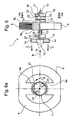
- synchronous electrical pump 1 illustrated therein comprises a supporting enclosure 2 incorporating a shaped body 3 to which there is connected a volute 4 which has an axial inlet 5 and a radial peripheral outlet 6 for the fluid being pumped.
- Pump 1 has a synchronous electric motor incorporating a permanent magnet rotor 7 rotatably mounted in a chamber 8 formed in body 3, between the polar extremities 9a ( Figures 1a and 1b ) of a stator 9 constructed of a stack of plates and connected to enclosure 2.
- At least one exciter winding in general single phase, is associated with stator 9, which in operation excites the poles of the stator simultaneously, conferring north polarity and south polarity magnetisation upon them alternately in time and space.
- stator 9 which in operation excites the poles of the stator simultaneously, conferring north polarity and south polarity magnetisation upon them alternately in time and space.
- rotor 7 is within stator 9, but the arrangement of these parts may be reversed.
- Rotor 7 is borne upon a shaft 10 which is rotatably mounted within body 3 through end bearings 11 and 12 ( Figure 1a ).
- Electrical pump 1 also comprises a rotor 13 which has a plurality of straight blades 14 which extend radially from a hollow hub 15.
- impeller 13 is connected rotatably to shaft 10 of rotor 7 through a coupling, indicated as a whole by 16 in Figures 2 and 2a , through which rotor 7 may be started up under no load before the latter drives the impeller in rotation.
- this coupling comprises a radial projection 17 from the rotor shaft and a projection in the form of an angular sector 18 which projects within the cavity of hub 15 of the impeller.
- the synchronous electric motor of a pump of the type described above produces a negligible torque on starting and also does not have a predetermined direction of rotation, being able to rotate in one direction or the other indifferently depending upon random starting conditions.
- US 5 039 286 discloses a pump with a mechanism preventing rotation in a direction opposite to the normal working direction of rotation.
- One object of this invention is to provide a synchronous electrical pump of the type initially described which makes it possible to overcome the abovementioned disadvantages of pumps according to the prior art without making it necessary to adopt special complex and costly electronic control devices.
- a synchronous electrical pump the rotor is mounted so that it can move axially with respect to the supporting enclosure and a ratchet coupling device of a type which is in itself known is provided between the said rotor and the said supporting enclosure. Return means tending to push it towards an axial coupled position in which the ratchet device is in operation and causes rotation of the rotor to take place in one predetermined direction only when running are associated with the rotor.
- a ratchet coupling device 20 comprises a toothed wheel 21 which can rotate about a fixed axis 21a and is provided with a crown of saw teeth 22 and a pawl or ratchet 23 which can rotate about an axis 23a substantially parallel to axis 21a and acting together with a spring 24 ( Figure 3b ).
- the arrangement is such that pawl 23 allows toothed wheel 21 to rotate only in a predetermined direction. Rotation in the opposite direction is prevented.
- the ratchet device is illustrated in the non-operating condition, in which pawl 23 is disengaged from teeth 22.
- Activation of the ratchet device is obtained through an axial displacement of either pawl or ratchet 23 or toothed wheel 21 so as to bring pawl 23 into the condition illustrated in Figure 3 in which it is engaged between two adjacent teeth of wheel 21.
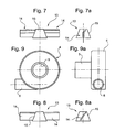
- Figures 3 and 5 and associated Figures 4a and 5a illustrate two different embodiments of ratchet devices 20 with a coupling of the frontal type.
- toothed wheel 21 has a plurality of frontal saw teeth 22 with which at least one pawl 23, preferably of resilient material, for example an elastomer, projecting from a frontal surface of a member 26 which is coaxial with wheel 21 can act.
- the coupling between this member 26 and toothed wheel 21 also in this case takes place through a relative axial movement between them.
- a synchronous electrical pump according to the invention has a volute 4 with a substantially tangential outlet 6, as for example illustrated in Figures 9 and 9a .
- the unit of the pump motor mounted with blades and the synchronous electric motor has the characteristics defined in appended claim 1, and will now be described in greater detail with reference to Figures 6 to 8a .
- parts and components which are essentially identical or equivalent to elements already described will be again allocated the same reference numbers as used previously.
- impeller 13 has blades 14 which are at least partly arcuate and are inclined relative to the axial direction of the impeller, for example as in the embodiments illustrated by way of example in Figures 7, 7a and 8, 8a .
- Rotor 7 with its corresponding shaft 10 is mounted with axial movement with respect to supporting enclosure 2 for the pump.
- shaft 10 of the rotor is mounted so that it can rotate and move axially in two end bearings 11 and 12 borne by corresponding supports 26 and 27 forming an integral part of supporting enclosure 2 (not illustrated in Figure 6 ).
- End support 26 has a frontal pawl or ratchet 23 which is able to act together with frontal saw teeth 22 of a member 21 forming an integral part of rotor 7.
- a helical spring 28 is inserted between stationary support 27 and rotor 7, and tends to push the latter towards an axial coupled position (not illustrated) in which ratchet device 20 comprising toothed formation 21 and pawl or ratchet 23 is active and ensures that rotor 7 only rotates in a predetermined direction under operating conditions.
- the profiling or at least partial inclination of blades 14 of impeller 13 is such that, as a result of their interaction with the fluid, rotation of impeller 13 at a speed higher than a predetermined value is likely to bring about lateral axial movement of said impeller 13 and rotor 7 relative to supporting enclosure 2 of the pump, against the force of spring 28, so that rotor 7 takes up the axial position illustrated in Figure 6 in which toothed formation 21 is disengaged from ratchet or pawl 23, and ratchet device 20 is deactivated, while nevertheless allowing rotor 7 to continue to rotate in the aforesaid predetermined direction.
- impeller 13 is coupled to shaft 10 of the rotor by means of a delay coupling 16, of a type which is in itself known and already described previously.
- spring 28 will be dimensioned in such a way that it can apply a force to the rotor/impeller complex which is greater than the force due to friction between shaft 10 and bearings 11 and 12, but still less than the reaction force exerted by the fluid on impeller 13 when this rotates at a speed higher than the aforesaid predetermined value.
- a similar modus operandi is also achieved without the use of spring 28 by replacing the returning mechanical action of the same with a magnetic force attracting rotor 7 towards the terminal surface 9b of the poles 9a of the stator ( Figure 6 ).
- This magnetic force can be produced by constructing the synchronous electric motor driving the pump in such a way that the frontal surface of the posterior extremity 7a of the rotor ( Figure 6 ) is suitably displaced in the direction of arrows C in relation to the terminal surface 9b of poles 9a of the stator.
- toothed formation 21 has two frontal saw teeth 22 which are angularly equally spaced apart.
- ratchet 23 is positioned between these teeth, with some angular play with respect to them.
- ratchet coupling device 20 may be provided between rotor 7 and support 27.
- the ratchet may be carried on the rotor, to act together with teeth 22 of wheels or stationary toothed formations.
Landscapes
- Engineering & Computer Science (AREA)
- Mechanical Engineering (AREA)
- General Engineering & Computer Science (AREA)
- Structures Of Non-Positive Displacement Pumps (AREA)
- Automatic Analysis And Handling Materials Therefor (AREA)
- Cyclones (AREA)
- Grinding-Machine Dressing And Accessory Apparatuses (AREA)
- Medicines Containing Plant Substances (AREA)
Claims (7)
- Eine elektrische Synchronpumpe (1) umfassend:- ein tragendes Gehäuse (2 - 4), welches einen Formkörper (3), an welchem ein Spiralgehäuse (4) gekoppelt ist, welches einen axialen Einlass (5) und einen peripheren, im Wesentlichen tangentialen Auslass (6) für das gepumpte Fluid aufweist, beinhaltet;- einen einphasigen elektrischen Synchronmotor (7, 9), welcher einen Permanentmagnetrotor (7), der rotierbar in einer Kammer (8), welche in dem Körper (3) gebildet ist, angebracht ist, angrenzend zu den polaren Extremitäten (9a) eines Stators (9), der mit dem Körper verbunden ist, beinhaltet; wobei der Rotor (7) in der Art angebracht ist, dass er in Bezug auf den Körper (3) lateral und axial beweglich ist; wobei eine Sperrklinkenkopplungsvorrichtung (20) zwischen dem Rotor (7) und dem tragenden Gehäuse (2 - 4) vorgesehen ist; wobei der Rotor (7) dazu geeignet ist eine axiale Kopplungsposition einzunehmen, in welcher die Sperrklinkenvorrichtung (20) aktiv ist und es für die Rotation des Rotors (7) ermöglicht in eine vorbestimmte Richtung zu starten; und- ein blatttragendes Flügelrad (13), welches in Rotation zu dem Rotor (7) des Motors (7, 9) gekoppelt ist;
wobei die Anordnung derart ist, dass als ein Ergebnis der Wechselwirkung mit dem Fluid die Rotation des Flügelrades (13) bei einer höheren Geschwindigkeit, als ein vorbestimmter Wert dazu geeignet ist laterale, axiale Bewegungen des Flügelrades (13) und des Rotors (7) relativ zu dem Körper (3) derart zu verursachen, dass der Rotor (7) eine axial gelöste Position, in welcher die Sperrklinkenvorrichtung (20) inaktiv ist, annimmt und der Rotor (7) fortfährt in der vorbestimmten Richtung zu rotieren;
die Pumpe (1) ist dadurch gekennzeichnet, dass
das Flügelrad (13) in Rotation mit dem Rotor (7) des Synchronmotors (7, 9) durch eine Kupplung (16) gekoppelt ist, durch welche dem Rotor (7) erlaubt ist ohne Last zu rotieren, wenn der Motor (7, 9) gestartet ist, bevor der Letztere das Flügelrad (13) veranlasst, angetrieben zu werden;
und dadurch, dass Rückstelleinrichtungen (28) mit dem Rotor (7) verbunden sind, die dazu neigen den Rotor (7) in Richtung der axialen Kopplungsposition zu drücken; wobei das Flügelrad (13), welches Blätter (14), die relative zu der axialen Richtung des Rotors (7) in der Art mindestens teilweise gebogen oder geneigt sind, dass die Rotation des Flügelrades (13) bei einer höheren Geschwindigkeit als der vorbestimmte Wert dazu geeignet ist eine axiale Bewegung des Flügelrades (13) und Rotors (7) entgegen der Kraft der Rückstelleinrichtungen (28) zu veranlassen. - Eine elektrische Synchronpumpe gemäß Anspruch 1, in welcher die Rückstelleinrichtungen Federeinrichtungen (28), die mechanisch auf den Rotor (7) wirken, umfassen.
- Eine elektrische Synchronpumpe gemäß Anspruch 1, in welcher der Rotor (7) und der Stator (9) in der Art gebaut sind, dass, wenn der Elektromotor (7, 9) aktiviert ist, der Stator (9) zur magnetischen Anziehung des Rotors (7) derart geeignet ist, dass er veranlasst wird sich axial zu bewegen, so dass die Sperrklinkenvorrichtung (20) von dem aktiven Zustand zu dem inaktiven Zustand übergeht.
- Eine elektrische Synchronpumpe gemäß einem der vorangegangenen Ansprüche, in welcher die Sperrklinkenkopplungsvorrichtung (20) mindestens eine Sperrklinke (23), bevorzugt aus elastischem Material umfasst, das dazu geeignet ist zusammen mit den Zähnen (22) einer Formation (21), welche sich in einer vorbestimmten Richtung relativ zu der Sperrklinke bewegen kann, zu wirken.
- Eine elektrische Synchronpumpe gemäß Anspruch 4, in welcher die mindestens eine Sperrklinke auf einem Teil (26), welches stationär relative zu dem tragenden Gehäuse (2 - 4) der Pumpe ist, angebracht ist und die gezahnte Formation (21) der Sperrklinkenvorrichtung (20) einen integralen Teil des Rotors (7) des Motors (7, 9) bildet.
- Eine elektrische Synchronpumpe gemäß Anspruch 4, in welcher die Sperrklinkenkopplungsvorrichtung (20) eine Sperrklinke (23) integral mit dem Rotor (7) des Elektromotors (7, 9) und einer gezahnten Formation (21), welche betrieblich stationär in Bezug auf das tragende Gehäuse (2 - 4) der Pumpe ist, umfasst.
- Eine elektrische Synchronpumpe gemäß Anspruch 5, in welcher sich die Sperrklinke (23) mit einem Winkelspiel zwischen aufeinanderfolgenden Zähnen (22) der gezahnten Formation (21) in der Art bewegen kann, dass, wenn der Elektromotor (7, 9) aktiviert ist, der Rotor (7) über einen begrenzten Winkel in die entgegengesetzte Richtung zu der vorbestimmten Richtung (D) zur Rotation unter Betriebsbedingungen rotieren kann.
Applications Claiming Priority (2)
| Application Number | Priority Date | Filing Date | Title |
|---|---|---|---|
| IT000016A ITBG20040016A1 (it) | 2004-05-05 | 2004-05-05 | Pompa sincrona con coclea tangenziale |
| PCT/IB2005/051470 WO2005106253A1 (en) | 2004-05-05 | 2005-05-04 | An electric synchronous pump with a volute having a tangential outlet |
Publications (2)
| Publication Number | Publication Date |
|---|---|
| EP1756428A1 EP1756428A1 (de) | 2007-02-28 |
| EP1756428B1 true EP1756428B1 (de) | 2010-07-07 |
Family
ID=34968586
Family Applications (1)
| Application Number | Title | Priority Date | Filing Date |
|---|---|---|---|
| EP05740448A Expired - Lifetime EP1756428B1 (de) | 2004-05-05 | 2005-05-04 | Elektrische synchronpumpe mit einem spiralgehäuse mit einem tangentialauslass |
Country Status (6)
| Country | Link |
|---|---|
| EP (1) | EP1756428B1 (de) |
| AT (1) | ATE473372T1 (de) |
| DE (1) | DE602005022189D1 (de) |
| ES (1) | ES2348643T3 (de) |
| IT (1) | ITBG20040016A1 (de) |
| WO (1) | WO2005106253A1 (de) |
Cited By (1)
| Publication number | Priority date | Publication date | Assignee | Title |
|---|---|---|---|---|
| DE102009013372B4 (de) * | 2009-03-07 | 2020-06-25 | Ziehl-Abegg Se | Ventilatoreinheit |
Families Citing this family (2)
| Publication number | Priority date | Publication date | Assignee | Title |
|---|---|---|---|---|
| IT1396749B1 (it) * | 2008-09-08 | 2012-12-14 | Emerson Appliance Motors Europe | Pompa elettrica sincrona monodirezionale, particolarmente per apparecchi elettrodomestici. |
| JP6181090B2 (ja) * | 2015-01-17 | 2017-08-16 | 株式会社鷺宮製作所 | 遠心ポンプ |
Family Cites Families (3)
| Publication number | Priority date | Publication date | Assignee | Title |
|---|---|---|---|---|
| US1663226A (en) * | 1926-05-11 | 1928-03-20 | Peerless Pump Co | Nonreversing means for pump heads |
| FR2649450A1 (fr) * | 1989-07-07 | 1991-01-11 | Rena Sa | Pompe rotative a entrainement electrique |
| IT1281839B1 (it) * | 1995-01-19 | 1998-03-03 | Askoll Srl | Dispositivo perfezionato di avviamento del rotore di un motore sincrono a magneti permanenti |
-
2004
- 2004-05-05 IT IT000016A patent/ITBG20040016A1/it unknown
-
2005
- 2005-05-04 WO PCT/IB2005/051470 patent/WO2005106253A1/en not_active Ceased
- 2005-05-04 EP EP05740448A patent/EP1756428B1/de not_active Expired - Lifetime
- 2005-05-04 AT AT05740448T patent/ATE473372T1/de not_active IP Right Cessation
- 2005-05-04 DE DE602005022189T patent/DE602005022189D1/de not_active Expired - Lifetime
- 2005-05-04 ES ES05740448T patent/ES2348643T3/es not_active Expired - Lifetime
Cited By (1)
| Publication number | Priority date | Publication date | Assignee | Title |
|---|---|---|---|---|
| DE102009013372B4 (de) * | 2009-03-07 | 2020-06-25 | Ziehl-Abegg Se | Ventilatoreinheit |
Also Published As
| Publication number | Publication date |
|---|---|
| EP1756428A1 (de) | 2007-02-28 |
| ITBG20040016A1 (it) | 2004-08-05 |
| WO2005106253A1 (en) | 2005-11-10 |
| ES2348643T3 (es) | 2010-12-10 |
| ATE473372T1 (de) | 2010-07-15 |
| DE602005022189D1 (de) | 2010-08-19 |
Similar Documents
| Publication | Publication Date | Title |
|---|---|---|
| US8186975B2 (en) | Low profile pump with first and second rotor arrangement | |
| US5039286A (en) | Electrically-driven rotary pump | |
| EP1212534B1 (de) | Unidirektionales laufrad für eine elektrische kreiselpumpe mit einem permanentmagnet synchronmotor | |
| CN103270305A (zh) | 输送泵 | |
| EP0810374A3 (de) | Kreiselpumpaggregat | |
| TW200522478A (en) | Fan motor | |
| EP1756428B1 (de) | Elektrische synchronpumpe mit einem spiralgehäuse mit einem tangentialauslass | |
| JP2005171825A5 (de) | ||
| PL1664541T3 (pl) | Maszyna z tłokiem obrotowym | |
| EP0383464B1 (de) | Pumpe | |
| US20070201988A1 (en) | Vacuum Pump | |
| CA2553795A1 (en) | Eccentric screw pump with integrated drive | |
| WO1994005073A2 (en) | Electric fan motor | |
| CN201474995U (zh) | 一种永磁同步电机水泵 | |
| WO2010025959A2 (en) | Unidirectional synchronous electric pump, particularly for electric household appliances | |
| EP1143148A2 (de) | Elektrisch angetriebene Kreiselpumpe mit vorgegebener Drehrichtung | |
| CN215566716U (zh) | 鼠笼盘式复合自启动永磁同步电机驱动的深井泵 | |
| CN115133707B (zh) | 一种改进的永磁同步马达 | |
| ATE295479T1 (de) | Leicht zu reinigende kreiselpumpe | |
| SU681214A1 (ru) | Насосно-компрессорный агрегат | |
| IT1315716B1 (it) | Girante monodirezionale per elettropompe centrifughe con motoresincrono a magneti permanenti. | |
| US9148039B2 (en) | Motor assembly | |
| JP2001207989A (ja) | 水中モータポンプ | |
| Krol | Combination Motor and Pump Assembly | |
| AU2001272356A1 (en) | Comminutor pump |
Legal Events
| Date | Code | Title | Description |
|---|---|---|---|
| PUAI | Public reference made under article 153(3) epc to a published international application that has entered the european phase |
Free format text: ORIGINAL CODE: 0009012 |
|
| 17P | Request for examination filed |
Effective date: 20061201 |
|
| AK | Designated contracting states |
Kind code of ref document: A1 Designated state(s): AT BE BG CH CY CZ DE DK EE ES FI FR GB GR HU IE IS IT LI LT LU MC NL PL PT RO SE SI SK TR |
|
| DAX | Request for extension of the european patent (deleted) | ||
| GRAP | Despatch of communication of intention to grant a patent |
Free format text: ORIGINAL CODE: EPIDOSNIGR1 |
|
| GRAS | Grant fee paid |
Free format text: ORIGINAL CODE: EPIDOSNIGR3 |
|
| GRAA | (expected) grant |
Free format text: ORIGINAL CODE: 0009210 |
|
| RAP1 | Party data changed (applicant data changed or rights of an application transferred) |
Owner name: ASKOLL P&C S.R.L. |
|
| AK | Designated contracting states |
Kind code of ref document: B1 Designated state(s): AT BE BG CH CY CZ DE DK EE ES FI FR GB GR HU IE IS IT LI LT LU MC NL PL PT RO SE SI SK TR |
|
| REG | Reference to a national code |
Ref country code: GB Ref legal event code: FG4D |
|
| REG | Reference to a national code |
Ref country code: CH Ref legal event code: EP |
|
| REG | Reference to a national code |
Ref country code: IE Ref legal event code: FG4D |
|
| REF | Corresponds to: |
Ref document number: 602005022189 Country of ref document: DE Date of ref document: 20100819 Kind code of ref document: P |
|
| REG | Reference to a national code |
Ref country code: NL Ref legal event code: VDEP Effective date: 20100707 |
|
| REG | Reference to a national code |
Ref country code: ES Ref legal event code: FG2A Effective date: 20101126 |
|
| PG25 | Lapsed in a contracting state [announced via postgrant information from national office to epo] |
Ref country code: SI Free format text: LAPSE BECAUSE OF FAILURE TO SUBMIT A TRANSLATION OF THE DESCRIPTION OR TO PAY THE FEE WITHIN THE PRESCRIBED TIME-LIMIT Effective date: 20100707 |
|
| LTIE | Lt: invalidation of european patent or patent extension |
Effective date: 20100707 |
|
| PG25 | Lapsed in a contracting state [announced via postgrant information from national office to epo] |
Ref country code: AT Free format text: LAPSE BECAUSE OF FAILURE TO SUBMIT A TRANSLATION OF THE DESCRIPTION OR TO PAY THE FEE WITHIN THE PRESCRIBED TIME-LIMIT Effective date: 20100707 Ref country code: FI Free format text: LAPSE BECAUSE OF FAILURE TO SUBMIT A TRANSLATION OF THE DESCRIPTION OR TO PAY THE FEE WITHIN THE PRESCRIBED TIME-LIMIT Effective date: 20100707 Ref country code: NL Free format text: LAPSE BECAUSE OF FAILURE TO SUBMIT A TRANSLATION OF THE DESCRIPTION OR TO PAY THE FEE WITHIN THE PRESCRIBED TIME-LIMIT Effective date: 20100707 Ref country code: LT Free format text: LAPSE BECAUSE OF FAILURE TO SUBMIT A TRANSLATION OF THE DESCRIPTION OR TO PAY THE FEE WITHIN THE PRESCRIBED TIME-LIMIT Effective date: 20100707 |
|
| PG25 | Lapsed in a contracting state [announced via postgrant information from national office to epo] |
Ref country code: CY Free format text: LAPSE BECAUSE OF FAILURE TO SUBMIT A TRANSLATION OF THE DESCRIPTION OR TO PAY THE FEE WITHIN THE PRESCRIBED TIME-LIMIT Effective date: 20100707 Ref country code: BG Free format text: LAPSE BECAUSE OF FAILURE TO SUBMIT A TRANSLATION OF THE DESCRIPTION OR TO PAY THE FEE WITHIN THE PRESCRIBED TIME-LIMIT Effective date: 20101007 Ref country code: PT Free format text: LAPSE BECAUSE OF FAILURE TO SUBMIT A TRANSLATION OF THE DESCRIPTION OR TO PAY THE FEE WITHIN THE PRESCRIBED TIME-LIMIT Effective date: 20101108 Ref country code: PL Free format text: LAPSE BECAUSE OF FAILURE TO SUBMIT A TRANSLATION OF THE DESCRIPTION OR TO PAY THE FEE WITHIN THE PRESCRIBED TIME-LIMIT Effective date: 20100707 Ref country code: IS Free format text: LAPSE BECAUSE OF FAILURE TO SUBMIT A TRANSLATION OF THE DESCRIPTION OR TO PAY THE FEE WITHIN THE PRESCRIBED TIME-LIMIT Effective date: 20101107 |
|
| PG25 | Lapsed in a contracting state [announced via postgrant information from national office to epo] |
Ref country code: SE Free format text: LAPSE BECAUSE OF FAILURE TO SUBMIT A TRANSLATION OF THE DESCRIPTION OR TO PAY THE FEE WITHIN THE PRESCRIBED TIME-LIMIT Effective date: 20100707 Ref country code: GR Free format text: LAPSE BECAUSE OF FAILURE TO SUBMIT A TRANSLATION OF THE DESCRIPTION OR TO PAY THE FEE WITHIN THE PRESCRIBED TIME-LIMIT Effective date: 20101008 Ref country code: BE Free format text: LAPSE BECAUSE OF FAILURE TO SUBMIT A TRANSLATION OF THE DESCRIPTION OR TO PAY THE FEE WITHIN THE PRESCRIBED TIME-LIMIT Effective date: 20100707 |
|
| PG25 | Lapsed in a contracting state [announced via postgrant information from national office to epo] |
Ref country code: DK Free format text: LAPSE BECAUSE OF FAILURE TO SUBMIT A TRANSLATION OF THE DESCRIPTION OR TO PAY THE FEE WITHIN THE PRESCRIBED TIME-LIMIT Effective date: 20100707 |
|
| PLBE | No opposition filed within time limit |
Free format text: ORIGINAL CODE: 0009261 |
|
| STAA | Information on the status of an ep patent application or granted ep patent |
Free format text: STATUS: NO OPPOSITION FILED WITHIN TIME LIMIT |
|
| PG25 | Lapsed in a contracting state [announced via postgrant information from national office to epo] |
Ref country code: SK Free format text: LAPSE BECAUSE OF FAILURE TO SUBMIT A TRANSLATION OF THE DESCRIPTION OR TO PAY THE FEE WITHIN THE PRESCRIBED TIME-LIMIT Effective date: 20100707 Ref country code: RO Free format text: LAPSE BECAUSE OF FAILURE TO SUBMIT A TRANSLATION OF THE DESCRIPTION OR TO PAY THE FEE WITHIN THE PRESCRIBED TIME-LIMIT Effective date: 20100707 Ref country code: CZ Free format text: LAPSE BECAUSE OF FAILURE TO SUBMIT A TRANSLATION OF THE DESCRIPTION OR TO PAY THE FEE WITHIN THE PRESCRIBED TIME-LIMIT Effective date: 20100707 Ref country code: EE Free format text: LAPSE BECAUSE OF FAILURE TO SUBMIT A TRANSLATION OF THE DESCRIPTION OR TO PAY THE FEE WITHIN THE PRESCRIBED TIME-LIMIT Effective date: 20100707 |
|
| 26N | No opposition filed |
Effective date: 20110408 |
|
| REG | Reference to a national code |
Ref country code: DE Ref legal event code: R097 Ref document number: 602005022189 Country of ref document: DE Effective date: 20110408 |
|
| PG25 | Lapsed in a contracting state [announced via postgrant information from national office to epo] |
Ref country code: MC Free format text: LAPSE BECAUSE OF NON-PAYMENT OF DUE FEES Effective date: 20110531 |
|
| REG | Reference to a national code |
Ref country code: CH Ref legal event code: PL |
|
| GBPC | Gb: european patent ceased through non-payment of renewal fee |
Effective date: 20110504 |
|
| PG25 | Lapsed in a contracting state [announced via postgrant information from national office to epo] |
Ref country code: CH Free format text: LAPSE BECAUSE OF NON-PAYMENT OF DUE FEES Effective date: 20110531 Ref country code: LI Free format text: LAPSE BECAUSE OF NON-PAYMENT OF DUE FEES Effective date: 20110531 |
|
| REG | Reference to a national code |
Ref country code: IE Ref legal event code: MM4A |
|
| PG25 | Lapsed in a contracting state [announced via postgrant information from national office to epo] |
Ref country code: IE Free format text: LAPSE BECAUSE OF NON-PAYMENT OF DUE FEES Effective date: 20110504 |
|
| PG25 | Lapsed in a contracting state [announced via postgrant information from national office to epo] |
Ref country code: GB Free format text: LAPSE BECAUSE OF NON-PAYMENT OF DUE FEES Effective date: 20110504 |
|
| PG25 | Lapsed in a contracting state [announced via postgrant information from national office to epo] |
Ref country code: LU Free format text: LAPSE BECAUSE OF NON-PAYMENT OF DUE FEES Effective date: 20110504 |
|
| PG25 | Lapsed in a contracting state [announced via postgrant information from national office to epo] |
Ref country code: HU Free format text: LAPSE BECAUSE OF FAILURE TO SUBMIT A TRANSLATION OF THE DESCRIPTION OR TO PAY THE FEE WITHIN THE PRESCRIBED TIME-LIMIT Effective date: 20100707 |
|
| REG | Reference to a national code |
Ref country code: FR Ref legal event code: PLFP Year of fee payment: 12 |
|
| REG | Reference to a national code |
Ref country code: FR Ref legal event code: PLFP Year of fee payment: 13 |
|
| REG | Reference to a national code |
Ref country code: FR Ref legal event code: PLFP Year of fee payment: 14 |
|
| PGFP | Annual fee paid to national office [announced via postgrant information from national office to epo] |
Ref country code: DE Payment date: 20180419 Year of fee payment: 14 |
|
| REG | Reference to a national code |
Ref country code: DE Ref legal event code: R119 Ref document number: 602005022189 Country of ref document: DE |
|
| PG25 | Lapsed in a contracting state [announced via postgrant information from national office to epo] |
Ref country code: DE Free format text: LAPSE BECAUSE OF NON-PAYMENT OF DUE FEES Effective date: 20191203 |
|
| PGFP | Annual fee paid to national office [announced via postgrant information from national office to epo] |
Ref country code: TR Payment date: 20200422 Year of fee payment: 16 Ref country code: ES Payment date: 20200602 Year of fee payment: 16 Ref country code: FR Payment date: 20200422 Year of fee payment: 16 |
|
| PGFP | Annual fee paid to national office [announced via postgrant information from national office to epo] |
Ref country code: IT Payment date: 20200421 Year of fee payment: 16 |
|
| PG25 | Lapsed in a contracting state [announced via postgrant information from national office to epo] |
Ref country code: FR Free format text: LAPSE BECAUSE OF NON-PAYMENT OF DUE FEES Effective date: 20210531 |
|
| REG | Reference to a national code |
Ref country code: ES Ref legal event code: FD2A Effective date: 20220727 |
|
| PG25 | Lapsed in a contracting state [announced via postgrant information from national office to epo] |
Ref country code: ES Free format text: LAPSE BECAUSE OF NON-PAYMENT OF DUE FEES Effective date: 20210505 |
|
| PG25 | Lapsed in a contracting state [announced via postgrant information from national office to epo] |
Ref country code: IT Free format text: LAPSE BECAUSE OF NON-PAYMENT OF DUE FEES Effective date: 20200504 |
|
| PG25 | Lapsed in a contracting state [announced via postgrant information from national office to epo] |
Ref country code: TR Free format text: LAPSE BECAUSE OF NON-PAYMENT OF DUE FEES Effective date: 20210504 |
|
| PG25 | Lapsed in a contracting state [announced via postgrant information from national office to epo] |
Ref country code: IT Free format text: LAPSE BECAUSE OF NON-PAYMENT OF DUE FEES Effective date: 20210504 |