EP1756443B1 - Accouplement hydrodynamique pourvu d'un dispositif de controle de vitesse et systeme a double recuperation d'energie par turbine - Google Patents
Accouplement hydrodynamique pourvu d'un dispositif de controle de vitesse et systeme a double recuperation d'energie par turbine Download PDFInfo
- Publication number
- EP1756443B1 EP1756443B1 EP05755579A EP05755579A EP1756443B1 EP 1756443 B1 EP1756443 B1 EP 1756443B1 EP 05755579 A EP05755579 A EP 05755579A EP 05755579 A EP05755579 A EP 05755579A EP 1756443 B1 EP1756443 B1 EP 1756443B1
- Authority
- EP
- European Patent Office
- Prior art keywords
- bolt
- hydrodynamic coupling
- coupling
- wheel
- locking device
- Prior art date
- Legal status (The legal status is an assumption and is not a legal conclusion. Google has not performed a legal analysis and makes no representation as to the accuracy of the status listed.)
- Expired - Fee Related
Links
Images

Classifications
-
- F—MECHANICAL ENGINEERING; LIGHTING; HEATING; WEAPONS; BLASTING
- F16—ENGINEERING ELEMENTS AND UNITS; GENERAL MEASURES FOR PRODUCING AND MAINTAINING EFFECTIVE FUNCTIONING OF MACHINES OR INSTALLATIONS; THERMAL INSULATION IN GENERAL
- F16D—COUPLINGS FOR TRANSMITTING ROTATION; CLUTCHES; BRAKES
- F16D33/00—Rotary fluid couplings or clutches of the hydrokinetic type
- F16D33/06—Rotary fluid couplings or clutches of the hydrokinetic type controlled by changing the amount of liquid in the working circuit
-
- F—MECHANICAL ENGINEERING; LIGHTING; HEATING; WEAPONS; BLASTING
- F02—COMBUSTION ENGINES; HOT-GAS OR COMBUSTION-PRODUCT ENGINE PLANTS
- F02B—INTERNAL-COMBUSTION PISTON ENGINES; COMBUSTION ENGINES IN GENERAL
- F02B41/00—Engines characterised by special means for improving conversion of heat or pressure energy into mechanical power
- F02B41/02—Engines with prolonged expansion
- F02B41/10—Engines with prolonged expansion in exhaust turbines
-
- F—MECHANICAL ENGINEERING; LIGHTING; HEATING; WEAPONS; BLASTING
- F16—ENGINEERING ELEMENTS AND UNITS; GENERAL MEASURES FOR PRODUCING AND MAINTAINING EFFECTIVE FUNCTIONING OF MACHINES OR INSTALLATIONS; THERMAL INSULATION IN GENERAL
- F16D—COUPLINGS FOR TRANSMITTING ROTATION; CLUTCHES; BRAKES
- F16D43/00—Automatic clutches
- F16D43/02—Automatic clutches actuated entirely mechanically
- F16D43/04—Automatic clutches actuated entirely mechanically controlled by angular speed
- F16D43/14—Automatic clutches actuated entirely mechanically controlled by angular speed with centrifugal masses actuating the clutching members directly in a direction which has at least a radial component; with centrifugal masses themselves being the clutching members
-
- F—MECHANICAL ENGINEERING; LIGHTING; HEATING; WEAPONS; BLASTING
- F16—ENGINEERING ELEMENTS AND UNITS; GENERAL MEASURES FOR PRODUCING AND MAINTAINING EFFECTIVE FUNCTIONING OF MACHINES OR INSTALLATIONS; THERMAL INSULATION IN GENERAL
- F16D—COUPLINGS FOR TRANSMITTING ROTATION; CLUTCHES; BRAKES
- F16D47/00—Systems of clutches, or clutches and couplings, comprising devices of types grouped under at least two of the following sets of groups: F16D1/00 - F16D9/00, F16D11/00 - F16D23/00, F16D25/00 - F16D29/00, F16D31/00 - F16D39/00, F16D41/00 - F16D45/00
- F16D47/06—Systems of clutches, or clutches and couplings, comprising devices of types grouped under at least two of the following sets of groups: F16D1/00 - F16D9/00, F16D11/00 - F16D23/00, F16D25/00 - F16D29/00, F16D31/00 - F16D39/00, F16D41/00 - F16D45/00 of which at least one is a clutch with a fluid or a semifluid as power-transmitting means
-
- F—MECHANICAL ENGINEERING; LIGHTING; HEATING; WEAPONS; BLASTING
- F16—ENGINEERING ELEMENTS AND UNITS; GENERAL MEASURES FOR PRODUCING AND MAINTAINING EFFECTIVE FUNCTIONING OF MACHINES OR INSTALLATIONS; THERMAL INSULATION IN GENERAL
- F16D—COUPLINGS FOR TRANSMITTING ROTATION; CLUTCHES; BRAKES
- F16D43/00—Automatic clutches
- F16D43/02—Automatic clutches actuated entirely mechanically
- F16D43/04—Automatic clutches actuated entirely mechanically controlled by angular speed
- F16D43/14—Automatic clutches actuated entirely mechanically controlled by angular speed with centrifugal masses actuating the clutching members directly in a direction which has at least a radial component; with centrifugal masses themselves being the clutching members
- F16D2043/145—Automatic clutches actuated entirely mechanically controlled by angular speed with centrifugal masses actuating the clutching members directly in a direction which has at least a radial component; with centrifugal masses themselves being the clutching members the centrifugal masses being pivoting
-
- Y—GENERAL TAGGING OF NEW TECHNOLOGICAL DEVELOPMENTS; GENERAL TAGGING OF CROSS-SECTIONAL TECHNOLOGIES SPANNING OVER SEVERAL SECTIONS OF THE IPC; TECHNICAL SUBJECTS COVERED BY FORMER USPC CROSS-REFERENCE ART COLLECTIONS [XRACs] AND DIGESTS
- Y02—TECHNOLOGIES OR APPLICATIONS FOR MITIGATION OR ADAPTATION AGAINST CLIMATE CHANGE
- Y02T—CLIMATE CHANGE MITIGATION TECHNOLOGIES RELATED TO TRANSPORTATION
- Y02T10/00—Road transport of goods or passengers
- Y02T10/10—Internal combustion engine [ICE] based vehicles
- Y02T10/12—Improving ICE efficiencies
Definitions
- the present invention relates to a hydrodynamic coupling, in particular for a turbocompound system, and more particularly to a turbocompound system with a hydrodynamic coupling.
- the hydrodynamic coupling in such a turbocompound system is for transmitting torque from an exhaust gas turbine disposed in the exhaust stream of an internal combustion engine to the crankshaft driven by the internal combustion engine to thereby increase the efficiency of the drivetrain.
- an exhaust gas turbine disposed in the exhaust stream of an internal combustion engine
- the crankshaft is driven via the hydrodynamic coupling by the exhaust gas utilization turbine
- a torque support of the useful turbine which avoids an uncontrolled upward rotation of the exhaust gas utilization turbine takes place. If, for some reason, such as loss of fill in the clutch circuit, this torque support be limited or turned off, there is a risk that the exhaust gas turbine comes in an overspeed range and takes damage.
- the document WO 00/55527 A describes a hydrodynamic coupling with a parallel lock-up clutch, wherein the filling and emptying of the hydrodynamic coupling takes place in dependence on the control of the lock-up clutch.
- the document GB-A-2 292 774 describes a supercharged internal combustion engine with an exhaust gas turbine and a hydrodynamic coupling.
- the invention has for its object to present a hydrodynamic coupling and in particular a turbocompound system with a hydrodynamic coupling according to the invention, which / which is improved over the prior art and in particular provides an automatic, without external energy exiting overspeed protection
- the hydrodynamic coupling according to claim 1 first, the usual components, such as a pump and a turbine wheel, which together form a working space.
- This working space is filled or filled with a working fluid.
- a working medium circuit is provided, which is also called coupling circuit.
- the hydrodynamic coupling has a locking device which is suitable for non-rotatably locking the impeller and the turbine wheel to one another.
- This locking device is connected to a working medium leading portion of the coupling, for example between the impeller and the turbine wheel, in particular between an outer shell of the impeller, which the turbine wheel on its back encloses, in conjunction, in such a way that it below a predetermined degree of filling of the working space, wherein the degree of filling in a (partial) filling and emptying of the working medium-carrying area closes closes closes.
- Closing in the sense of the present invention means a rotationally fixed locking of impeller and turbine to each other.
- the closing is advantageously carried out automatically, that is to say without a manual actuation effected from outside the coupling, in particular automatically under the influence of centrifugal force necessarily occurring during the operation of the hydrodynamic coupling.
- the mechanical locking device is designed in the form of a lock-up clutch which automatically engages and disengages, in particular under the influence of centrifugal force necessarily occurring during operation.
- the mechanical locking device can be designed such that it simultaneously represents an overspeed protection for the hydrodynamic coupling in addition to its monitoring function for the degree of filling of the working space.
- it is, for example, by providing a centrifugal force element, d. H. an element having a predetermined mass which shifts radially outward above a predetermined rotational speed by the centrifugal force, designed to close above a predetermined rotational speed of the impeller or the turbine wheel.
- the closing of the locking device which is advantageously designed as a lock-up clutch, in particular automatically, that is, the lock-up clutch moves automatically, for example, under the necessarily occurring during operation of centrifugal force on and off.
- a mechanical connection takes its place.
- this may be a connection of the clutch outer part, that is, the shell of the impeller, with the inner wheel, that is, the turbine wheel, be.
- the coupling shell which revolves through the connection with the impeller with impeller speed, can be connected, for example via a transmission, usually a gear drive, with the power turbine, while the inner wheel, that is, the turbine wheel, via a transmission, usually a gear drive , is connected to the crankshaft.
- a displaceable in the radial direction of the coupling bolt can be arranged, and also an opening with which the bolt is aligned.
- the bolt engages or passes through the opening in a first, locking position when the mechanical locking device closes. In a second position, that is the open position of the locking device, the bolt is completely outside the opening.
- Whether the bolt engages in the opening or not is determined by the degree of filling in the working space in that in the case that the locking device is opened, the working medium exerts a displacement force on the bolt, so that the bolt is displaced out of the opening.
- this displacing working fluid is not present in the corresponding working fluid carrying area, and the bolt is pushed into or through the opening by a suitable pressure means, for example a compression spring.
- the bolt thus remains securely in its intended position out of engagement with the opening at any speed of normal operation.
- the centrifugal force F z outweighs the forces opposite it, which causes the bolt slides into the opening and rotatably locked impeller and turbine wheel together.
- the same movement of the bolt also occurs when the buoyancy force is still present, but due to overspeeds, the centrifugal force F z increases so far that it overcomes their opposing forces despite the comparatively large buoyancy force.
- the bolt engages after entering the opening, so as to produce an emergency synchronization between the crankshaft and the exhaust gas turbine, which is maintained until the bolt is manually disengaged again.
- the bolt automatically returns to its original position, that is to say in its radially inward position, after the motor has been stopped.
- no “floating" bolt but a “floating” rocker arm is provided between the coupling shell and the inner wheel.
- This rocker arm can operate in accordance with the above-described operating principle of the bolt, that is, assume a first position at which the turbine can rotate relative to the impeller or the inner wheel relative to the clutch shell, and a second position in which the rocker arm pump and Turbine or the inner wheel and the clutch shell rotatably locked together.
- rocker arms and its counterpart for example in the form of an opening into which the rocker arm engages, may be provided, like the previously described bolt, in the area between the coupling shell and the rear side of the turbine wheel.
- a rocker arm between two frontally opposed clutch wheels generally the primary wheel (impeller) and the secondary wheel (turbine) and be arranged for locking in predetermined states of the two.
- the position of the rocker arm is advantageously adjusted according to the design of the bolt by the level of the clutch, the centrifugal force on the rocker arm, a spring force on the rocker arm and the rotational pressure on the rocker arm.
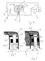
- FIG. 1 shows the hydrodynamic coupling 13, which is arranged in a drive connection between the crankshaft driven by the internal combustion engine 11 and the exhaust gas utilization turbine 10 which is acted upon by exhaust gas of the internal combustion engine 11.
- the hydrodynamic coupling 13 has an impeller 1 and a turbine wheel 2.
- the impeller 1 is in drive connection with the exhaust gas utilization turbine 10 via the transmission 7.
- the turbine wheel 2 is in driving connection with the crankshaft 12 via the transmission 8.
- the impeller 1 and the turbine wheel 2 form together a working space 4, in which the working medium 3 circulates, see the direction indicated by the arrow in the working space 4 direction of circulation.
- the working fluid 3 is accelerated radially outward in the impeller 1 and retarded radially inward in the turbine wheel 2.
- About the circulation flow of the working medium 3 is transmitted from the impeller 1 to the turbine 2 torque.
- the working medium 3 is supplied for example in the center or approximately in the center of the working medium circuit (not shown) and from the working space 4 radially outward into a region between the back of the turbine wheel 2, that is, the side opposite the working space 4, and a Outer shell 1.1, which is rotatably connected to the impeller 1 and the turbine wheel 2 encloses, dissipated. This removal always occurs at one partial or complete emptying of the working space 4 a. However, even in the case that there is a constant amount of working medium 3 in the working space 4, a corresponding working medium level in the area between the turbine wheel 2 and the outer shell 1.1 set.
- FIG. 2 again shows a schematic detail view of the region from FIG. 1, in which the locking device 5 according to the invention is arranged. Both in the figure 1 and in Figure 2, the axis of rotation 6 of the hydrodynamic coupling is indicated by a dashed line.
- FIG. 2 again clearly shows the level of the working medium 3 in the region of the mechanical locking device 5, in FIG. 2a in "normal operation", while FIG. 2b shows an operating state in which, for some reason, the working medium unintentionally emerges from the hydrodynamic coupling has leaked.
- the opening 5.2 is introduced in a projection 5. 5, which is formed on the rear side of the turbine wheel 2.
- the bolt 5.1 slides with its cylindrical shaft 5.1.2 within a guide 5.4, which encloses the shaft 5.1.2 in the circumferential direction.
- Radially inside is on the shaft 5.1.2 a thickened, that is provided with a larger diameter head area 5.1.1 connected.
- a shoulder 5.1.3 is formed radially outward on the head area 5.1.1, on which the spring engages 5.3 with its radially inner axial end. With its opposite, radially outer axial end, the spring engages 5.3 on the guide 5.4. Since the spring 5.3 is formed as a compression spring, it thus exerts a force in the radial direction inwards on the bolt 5.1.
- FIG. 3 shows a locking mechanism modified with respect to FIGS. 1 and 2 in an opened state (FIG. 3 a) and a locked state (FIG. 3 b).
- Figure 3 shows two sectional views in a radial section approximately through the position of the longitudinal axis of the bolt in Figures 1 and 2, although in the embodiment of Figure 3, of course, no bolt is provided.
- a rocker arm 5.11 which is connected in an articulated manner to the impeller 1, is provided, which is pivotable radially outward about an axis parallel to the axis of rotation of the coupling.
- the rocker arm 5.11 is held in the unlocked position shown in Figure 3a against the force of the compression spring 5.13 and the centrifugal force by the buoyancy force of the working fluid, see the liquid level shown.
- an aluminum weight (in particular in the form of the described bolt 5.1) have a diameter of 10 mm and a length of 200 mm. All dimensions of this description are to be regarded as preferable values, which are advantageously maintained approximately.
- the aluminum weight is immersed, for example, to 75% in the working fluid when the hydrodynamic coupling is in the nominal state, that is, a predetermined degree of filling is not exceeded.
- the system can be tuned so that at a speed of, for example, 8586 per minute, the piston extends, that is, the mechanical locking device closes. This prevents an overspeed of more than 8586 per minute.
- the degree of filling of the working space in the coupling decreases, a reduced buoyancy, and thus in particular only the spring force, which bears against the bolt, counteracts the centrifugal force which acts on the bolt.
- the closing of the mechanical locking device is therefore earlier, for example, within the normal operating range of the hydrodynamic coupling, that is within a speed range, which is permissible when the clutch is filled or a predetermined degree of filling of the working space of the clutch.
- both the buoyancy force and the restoring force are equal to zero due to the rotary pressure. This results in a switching speed of 4730 per minute. A run through of the turbine is thus reliably prevented.
Landscapes
- Engineering & Computer Science (AREA)
- General Engineering & Computer Science (AREA)
- Mechanical Engineering (AREA)
- Chemical & Material Sciences (AREA)
- Combustion & Propulsion (AREA)
- Supercharger (AREA)
- Structures Of Non-Positive Displacement Pumps (AREA)
- One-Way And Automatic Clutches, And Combinations Of Different Clutches (AREA)
- Control Of Turbines (AREA)
Abstract
Claims (11)
- Accouplement hydrodynamique (13) en particulier pour un système turbocompound comportant :1.1. un impulseur (1)1.2. une turbine réceptrice (2), ladite turbine constituant avec l'impulseur (1) une chambre de travail (4) pouvant être remplie d'un fluide (3) ;1.3. un dispositif de verrouillage mécanique (5) solidarisant en rotation l'impulseur (1) et la turbine réceptrice (2), caractérisé en ceci que ledit dispositif de verrouillage mécanique est en liaison avec une zone dudit accouplement (13) conduisant du fluide de telle sorte qu'il verrouille en dessous d'un degré de remplissage spécifié de la chambre de travail (4).
- Accouplement hydrodynamique (13) selon la revendication 1, caractérisé en ceci que ledit dispositif de verrouillage mécanique (5) est constitué de telle manière que, de plus, il verrouille au-dessus d'une vitesse de rotation spécifiée de l'impulseur (1) ou de la turbine réceptrice (2).
- Accouplement hydrodynamique (13) selon la revendication 1 ou 2, caractérisé en ceci que :3.1 ledit dispositif de verrouillage mécanique (5) présente en direction radiale de l'accouplement un doigt (5.1) coulissant et une ouverture (5.2) dans laquelle ledit doigt (5.1) peut s'engrener ;3.2 ledit doigt (5.1) est fixé solidairement en rotation avec l'un des deux volants (1, 2), en particulier avec ledit impulseur (1), et l'ouverture (5.2) est disposée sur l'autre volant (1, 2), en particulier sur ladite turbine réceptrice (2) ;3.3 ledit doigt (5.1) est immergé dans ledit fluide (3), lorsque le degré de remplissage spécifié est atteint ou dépassé, de manière à ce qu'au moins avec le concours de la poussée verticale (FA) dudit fluide (3) il soit poussé hors de l'ouverture (5.2) ;3.4 un moyen de pression, en particulier un ressort de compression (5.3) est prévu agissant contre la poussée verticale (FA) dudit fluide (3) sur ledit doigt (5.1), si bien qu'en dessous du degré de remplissage spécifié, ledit doigt (5.1) s'engrène dans ladite ouverture (5.2).
- Accouplement hydrodynamique (13) selon la revendication 3,
caractérisé en ceci que ledit doigt (5.1) présente une forme cylindrique et que son axe longitudinal est perpendiculaire à l'axe de rotation (6) dudit accouplement (13). - Accouplement hydrodynamique (13) selon une des revendications 3 ou 4, caractérisé en ceci que ledit impulseur (1) présente une coque externe (1.1), qui enserre ladite turbine réceptrice (2) sur sa face opposée à ladite chambre de travail (4) et en ceci que ledit dispositif de verrouillage mécanique (5) est disposé dans l'espace entre ladite coque externe (1.1) et ladite turbine réceptrice (2).
- Accouplement hydrodynamique (13) selon la revendication 5, caractérisé en ceci que ledit doigt (5.1) glisse dans un guidage (5.4) fixé à ladite coque externe (1.1) ou constitue intégralement une seule pièce avec elle et en ceci que ladite ouverture (5.2) est constituée dans une saillie (5.5) à ladite turbine réceptrice (2), en particulier constitué dans l'alignement avec ledit guidage (5.4).
- Accouplement hydrodynamique (13) selon la revendication 6, caractérisé en ceci que ledit doigt (5.1) est muni à son extrémité interne radiale d'une tête (5.1.1) présentant un diamètre extérieur agrandi par rapport à une tige (5.1.2) dudit doigt (5.1) suivant directement radialement vers l'extérieur, de manière à ce qu'un épaulement (5.1.3) soit constitué, et en ceci qu'un ressort de compression (5.3), qui est prévu comme moyen de pression, s'appuie contre ledit épaulement (5.1.3) et radialement en direction opposée dudit guidage (5.4).
- Accouplement hydrodynamique (13) selon une des revendications 3 et 7, caractérisé en ceci que ledit ressort de compression (5.3) présente une force de ressort (FR) et ledit doigt (5.1) une masse (m) telles que ledit dispositif de verrouillage mécanique (5) verrouille au-dessus de la vitesse de rotation spécifiée indépendamment du niveau de remplissage de ladite chambre de travail (4).
- Accouplement hydrodynamique (13) selon une des revendications 1 ou 2, caractérisé en ceci que :9.1 ledit dispositif de verrouillage mécanique (5) présente un culbuteur (5.11) pivotant en direction radiale de l'accouplement et une ouverture (5.12) dans laquelle ledit culbuteur (5.11) peut s'engrener ;9.2 ledit culbuteur (5.11) est fixé immobile à l'un des deux volants (1, 2), en particulier audit impulseur (1), et que ladite ouverture (5.12) est disposée sur l'autre volant (1, 2), en particulier sur ladite turbine réceptrice (2) ;9.3 ledit culbuteur (5.11) est immergé dans ledit fluide (3), lorsque le degré de remplissage spécifié est atteint ou dépassé, de manière à ce qu'au moins avec le concours de la poussée verticale (FA) dudit fluide (3) il soit poussé hors de ladite ouverture (5.12) ;9.4 un moyen de pression, en particulier un ressort de compression (5.13), est prévu agissant contre la poussée verticale (FA) dudit fluide (3) sur ledit culbuteur (5.11), si bien qu'en dessous du degré de remplissage spécifié, ledit culbuteur (5.11) s'engrène dans ladite ouverture (5.12).
- Accouplement hydrodynamique (13) selon, une des revendications 1 à 9, caractérisé en ceci que ledit dispositif de verrouillage mécanique (5) soit muni d'un moyen par lequel ledit dispositif de verrouillage mécanique (5), après son verrouillage, soit maintenu verrouillé jusqu'à ce qu'on l'actionne manuellement.
- Système turbocompound comportant une turbine de récupération sur gaz d'échappement (10), qui est disposée dans le flux des gaz d'échappement (9) d'un moteur à combustion (11),11.1 ledit moteur à combustion (11) entraînant un vilebrequin (12), et11.2 ladite turbine de récupération sur gaz d'échappement (10) pouvant être embrayée ou étant embrayée en liaison d'entraînement avec ledit vilebrequin (12),
caractérisé en ceci que11.3 dans la liaison d'entraînement, un accouplement hydrodynamique (13) selon une des revendications 1 à 9 est disposé dont l'impulseur (1) est en liaison d'entraînement avec ladite turbine de récupération des d'échappement (10) et dont la turbine réceptrice (2) est en liaison d'entraînement avec ledit vilebrequin (12).
Applications Claiming Priority (2)
| Application Number | Priority Date | Filing Date | Title |
|---|---|---|---|
| DE102004029656A DE102004029656A1 (de) | 2004-06-18 | 2004-06-18 | Hydrodynamische Kupplung mit Drehzahlschutz und Turbocompound-System |
| PCT/EP2005/006380 WO2005124176A1 (fr) | 2004-06-18 | 2005-06-15 | Accouplement hydrodynamique pourvu d'un dispositif de controle de vitesse et systeme a double recuperation d'energie par turbine |
Publications (2)
| Publication Number | Publication Date |
|---|---|
| EP1756443A1 EP1756443A1 (fr) | 2007-02-28 |
| EP1756443B1 true EP1756443B1 (fr) | 2007-11-14 |
Family
ID=34971314
Family Applications (1)
| Application Number | Title | Priority Date | Filing Date |
|---|---|---|---|
| EP05755579A Expired - Fee Related EP1756443B1 (fr) | 2004-06-18 | 2005-06-15 | Accouplement hydrodynamique pourvu d'un dispositif de controle de vitesse et systeme a double recuperation d'energie par turbine |
Country Status (9)
| Country | Link |
|---|---|
| US (1) | US20090255252A1 (fr) |
| EP (1) | EP1756443B1 (fr) |
| JP (1) | JP2008502853A (fr) |
| KR (1) | KR20070024615A (fr) |
| CN (1) | CN100439737C (fr) |
| BR (1) | BRPI0512199A (fr) |
| DE (2) | DE102004029656A1 (fr) |
| RU (1) | RU2377453C2 (fr) |
| WO (1) | WO2005124176A1 (fr) |
Families Citing this family (4)
| Publication number | Priority date | Publication date | Assignee | Title |
|---|---|---|---|---|
| DE202010012900U1 (de) * | 2010-11-16 | 2012-02-17 | Technische Universität Chemnitz | Schaltbare Kupplung, insbesondere mit elektrisch, hydraulisch oder pneumatisch aktuiertem Betätigungssystem |
| KR101963493B1 (ko) * | 2017-03-14 | 2019-03-28 | 브이에스이앤지(주) | 펌프용 무전원 기계식 속도 제어장치가 내장된 유체 커플링 장치 |
| RU2700106C1 (ru) * | 2019-01-17 | 2019-09-12 | Михаил Магомедович Омаров | Гидродинамическая автоматическая коробка передач |
| CN120333805B (zh) * | 2025-06-18 | 2025-09-02 | 雅安职业技术学院 | 一种新能源汽车用疲劳强度测试设备 |
Family Cites Families (16)
| Publication number | Priority date | Publication date | Assignee | Title |
|---|---|---|---|---|
| US2267334A (en) * | 1939-09-13 | 1941-12-23 | Rex E Keller | Automatic lockup for fluid drive clutches |
| DE920699C (de) * | 1941-07-24 | 1954-12-06 | Borg Warner | Zusammengesetzte Wellenkupplung |
| US2397862A (en) * | 1943-11-12 | 1946-04-02 | Jencick Stephen | Fluid coupling |
| DE1006731B (de) * | 1955-03-03 | 1957-04-18 | Fichtel & Sachs Ag | Anordnung zur automatischen Betaetigung einer mit einer hydrodynamischen Kupplung verbundenen mechanischen Kupplung, insbesondere fuer Kraftfahrzeuge |
| DE3345524A1 (de) * | 1983-12-16 | 1985-07-04 | Adam Opel AG, 6090 Rüsselsheim | Kupplung fuer fahrzeuge, insbesondere kraftfahrzeuge |
| DE3409692A1 (de) * | 1984-03-16 | 1985-09-19 | Daimler-Benz Ag, 7000 Stuttgart | Antriebsanordnung eines kraftfahrzeuges mit einer hydrodynamischen stroemungskupplung und einem von hand schaltbaren gangwechselgetriebe |
| JPS6192726A (ja) * | 1984-10-12 | 1986-05-10 | Fujitsu Ltd | 曲げ加工用プレス金型 |
| CN85205731U (zh) * | 1985-12-23 | 1986-08-13 | 城乡建设环境保护部长沙建筑机械研究所 | 新型液力偶合器 |
| DE3609377A1 (de) * | 1986-03-20 | 1987-09-24 | Bayerische Motoren Werke Ag | Hydrodynamische kupplung mit parksperre |
| CN86201522U (zh) * | 1986-04-01 | 1987-07-08 | 上海铁道学院 | 自动闭锁式液力偶合器 |
| SE502721C2 (sv) * | 1994-05-13 | 1995-12-18 | Scania Cv Ab | Förbränningsmotor av turbocompoundtyp med avgasbroms |
| DE4429855C1 (de) * | 1994-08-23 | 1995-08-17 | Daimler Benz Ag | Aufgeladene Brennkraftmaschine mit mechanischer Hochtriebsmöglichkeit eines Abgasturboladers |
| JP2002539395A (ja) * | 1999-03-12 | 2002-11-19 | フォイト・ターボ・ゲーエムベーハー・ウント・コンパニー・カーゲー | 始動ユニット |
| JP2004507691A (ja) * | 2000-08-31 | 2004-03-11 | ヴォイス・ターボ・ゲーエムベーハー・ウント・コ・カーゲー | 発進ユニット |
| EP1364139B1 (fr) * | 2000-12-04 | 2005-03-02 | Ebara Corporation | Coupleur hydraulique |
| KR20030077032A (ko) * | 2001-03-01 | 2003-09-29 | 보이트 터보 게엠베하 운트 콤파니 카게 | 내연기관 및 배기가스 과급기를 구비한 구동 유닛 |
-
2004
- 2004-06-18 DE DE102004029656A patent/DE102004029656A1/de not_active Withdrawn
-
2005
- 2005-06-15 KR KR1020067026658A patent/KR20070024615A/ko not_active Ceased
- 2005-06-15 RU RU2007101722/11A patent/RU2377453C2/ru not_active IP Right Cessation
- 2005-06-15 US US11/569,392 patent/US20090255252A1/en not_active Abandoned
- 2005-06-15 WO PCT/EP2005/006380 patent/WO2005124176A1/fr not_active Ceased
- 2005-06-15 BR BRPI0512199-0A patent/BRPI0512199A/pt not_active IP Right Cessation
- 2005-06-15 EP EP05755579A patent/EP1756443B1/fr not_active Expired - Fee Related
- 2005-06-15 DE DE502005001998T patent/DE502005001998D1/de not_active Expired - Lifetime
- 2005-06-15 JP JP2007515863A patent/JP2008502853A/ja active Pending
- 2005-06-15 CN CNB2005800197377A patent/CN100439737C/zh not_active Expired - Fee Related
Also Published As
| Publication number | Publication date |
|---|---|
| RU2377453C2 (ru) | 2009-12-27 |
| CN1985101A (zh) | 2007-06-20 |
| KR20070024615A (ko) | 2007-03-02 |
| CN100439737C (zh) | 2008-12-03 |
| WO2005124176A1 (fr) | 2005-12-29 |
| RU2007101722A (ru) | 2008-07-27 |
| US20090255252A1 (en) | 2009-10-15 |
| DE102004029656A1 (de) | 2006-01-19 |
| DE502005001998D1 (de) | 2007-12-27 |
| JP2008502853A (ja) | 2008-01-31 |
| BRPI0512199A (pt) | 2008-02-19 |
| EP1756443A1 (fr) | 2007-02-28 |
Similar Documents
| Publication | Publication Date | Title |
|---|---|---|
| DE2600523C3 (de) | Andrehvorrichtung für eine Gasturbinenanlage | |
| DE10219753B4 (de) | Hydrodynamische Bremse | |
| DE60026062T2 (de) | Freilaufkupplungseinrichtung | |
| DE69317106T2 (de) | Kupplungseinheit eines automatischen mechanischen Getriebes | |
| DE69919827T2 (de) | Turbinenlager | |
| WO2005068800A1 (fr) | Dispositif de transfert d'une puissance motrice a accouplement en sens contraire hydrodynamique | |
| CH620746A5 (fr) | ||
| DE102008031010A1 (de) | Zwei-Kanal Mehrfunktionsdrehmomentwandler | |
| DE3240334C2 (de) | Hydrodynamische Kupplung | |
| CH390007A (de) | Selbsteinrückende Synchronzahnkupplung | |
| EP1756443B1 (fr) | Accouplement hydrodynamique pourvu d'un dispositif de controle de vitesse et systeme a double recuperation d'energie par turbine | |
| DE2236832C3 (fr) | ||
| DE69202892T2 (de) | Föttinger Kupplung mit fester Flüssigkeitsmenge und Haupt- und Hilfsverzögerungskammer. | |
| EP1697651B1 (fr) | Accouplement hydrodynamique | |
| DE3522174C1 (de) | Hydrodynamische Kupplung | |
| DE3540408A1 (de) | Zweigangantrieb mit zwei riemenscheiben und einer fliehkrafttreibungskupplung | |
| EP1127231B1 (fr) | Embrayage hydrodynamique | |
| DE2500468A1 (de) | Trennkupplung fuer antriebswellen | |
| DE3142797A1 (de) | Kupplungsanordnung fuer einen schiffsantrieb | |
| DE3906500C2 (de) | Flügelzellenpumpen-Getriebekupplung | |
| EP1971788A1 (fr) | Coupleur hydrodynamique | |
| WO2007107314A1 (fr) | Ensemble hydrodynamique comprenant un ralentisseur et un accouplement hydrodynamique | |
| DE2326951A1 (de) | Rotierender phasenschieber zwischen zwei wellen | |
| DE3914634A1 (de) | Kupplungsanordnung in einem antrieb fuer nutzfahrzeuge | |
| EP0512405B1 (fr) | Accouplement hydrodynamique |
Legal Events
| Date | Code | Title | Description |
|---|---|---|---|
| PUAI | Public reference made under article 153(3) epc to a published international application that has entered the european phase |
Free format text: ORIGINAL CODE: 0009012 |
|
| 17P | Request for examination filed |
Effective date: 20061111 |
|
| AK | Designated contracting states |
Kind code of ref document: A1 Designated state(s): DE |
|
| GRAP | Despatch of communication of intention to grant a patent |
Free format text: ORIGINAL CODE: EPIDOSNIGR1 |
|
| GRAS | Grant fee paid |
Free format text: ORIGINAL CODE: EPIDOSNIGR3 |
|
| DAX | Request for extension of the european patent (deleted) | ||
| RBV | Designated contracting states (corrected) |
Designated state(s): DE |
|
| GRAA | (expected) grant |
Free format text: ORIGINAL CODE: 0009210 |
|
| AK | Designated contracting states |
Kind code of ref document: B1 Designated state(s): DE |
|
| REF | Corresponds to: |
Ref document number: 502005001998 Country of ref document: DE Date of ref document: 20071227 Kind code of ref document: P |
|
| PLBE | No opposition filed within time limit |
Free format text: ORIGINAL CODE: 0009261 |
|
| STAA | Information on the status of an ep patent application or granted ep patent |
Free format text: STATUS: NO OPPOSITION FILED WITHIN TIME LIMIT |
|
| 26N | No opposition filed |
Effective date: 20080815 |
|
| PGFP | Annual fee paid to national office [announced via postgrant information from national office to epo] |
Ref country code: DE Payment date: 20100708 Year of fee payment: 6 |
|
| REG | Reference to a national code |
Ref country code: DE Ref legal event code: R119 Ref document number: 502005001998 Country of ref document: DE Effective date: 20120103 |
|
| PG25 | Lapsed in a contracting state [announced via postgrant information from national office to epo] |
Ref country code: DE Free format text: LAPSE BECAUSE OF NON-PAYMENT OF DUE FEES Effective date: 20120103 |