EP1757192B1 - Dispositif et procédé destiné a tempérer des articles - Google Patents
Dispositif et procédé destiné a tempérer des articles Download PDFInfo
- Publication number
- EP1757192B1 EP1757192B1 EP06017036A EP06017036A EP1757192B1 EP 1757192 B1 EP1757192 B1 EP 1757192B1 EP 06017036 A EP06017036 A EP 06017036A EP 06017036 A EP06017036 A EP 06017036A EP 1757192 B1 EP1757192 B1 EP 1757192B1
- Authority
- EP
- European Patent Office
- Prior art keywords
- guide
- temperature
- air
- objects
- hollow body
- Prior art date
- Legal status (The legal status is an assumption and is not a legal conclusion. Google has not performed a legal analysis and makes no representation as to the accuracy of the status listed.)
- Expired - Lifetime
Links
- 238000000034 method Methods 0.000 title claims abstract description 10
- 238000005496 tempering Methods 0.000 title description 23
- 238000001816 cooling Methods 0.000 claims abstract description 33
- 239000007788 liquid Substances 0.000 claims description 8
- XLYOFNOQVPJJNP-UHFFFAOYSA-N water Substances O XLYOFNOQVPJJNP-UHFFFAOYSA-N 0.000 claims description 7
- 125000006850 spacer group Chemical group 0.000 claims description 3
- 235000009508 confectionery Nutrition 0.000 claims 2
- 235000015895 biscuits Nutrition 0.000 abstract description 7
- 238000009833 condensation Methods 0.000 description 4
- 230000005494 condensation Effects 0.000 description 4
- 238000004378 air conditioning Methods 0.000 description 2
- 241000792859 Enema Species 0.000 description 1
- 230000001174 ascending effect Effects 0.000 description 1
- 239000002826 coolant Substances 0.000 description 1
- 239000007920 enema Substances 0.000 description 1
- 229940095399 enema Drugs 0.000 description 1
- 238000000265 homogenisation Methods 0.000 description 1
- 238000004519 manufacturing process Methods 0.000 description 1
- 239000000463 material Substances 0.000 description 1
- 238000002156 mixing Methods 0.000 description 1
- 238000000465 moulding Methods 0.000 description 1
- 230000008092 positive effect Effects 0.000 description 1
- 230000000630 rising effect Effects 0.000 description 1
- 238000005096 rolling process Methods 0.000 description 1
Images


Classifications
-
- A—HUMAN NECESSITIES
- A23—FOODS OR FOODSTUFFS; TREATMENT THEREOF, NOT COVERED BY OTHER CLASSES
- A23G—COCOA; COCOA PRODUCTS, e.g. CHOCOLATE; SUBSTITUTES FOR COCOA OR COCOA PRODUCTS; CONFECTIONERY; CHEWING GUM; ICE-CREAM; PREPARATION THEREOF
- A23G7/00—Other apparatus or process specially adapted for the chocolate or confectionery industry
- A23G7/0043—Other processes specially adapted for the chocolate or confectionery industry
- A23G7/0093—Cooling or drying
-
- A—HUMAN NECESSITIES
- A23—FOODS OR FOODSTUFFS; TREATMENT THEREOF, NOT COVERED BY OTHER CLASSES
- A23G—COCOA; COCOA PRODUCTS, e.g. CHOCOLATE; SUBSTITUTES FOR COCOA OR COCOA PRODUCTS; CONFECTIONERY; CHEWING GUM; ICE-CREAM; PREPARATION THEREOF
- A23G1/00—Cocoa; Cocoa products, e.g. chocolate; Substitutes therefor
- A23G1/04—Apparatus specially adapted for manufacture or treatment of cocoa or cocoa products
- A23G1/18—Apparatus for conditioning chocolate masses for moulding
-
- A—HUMAN NECESSITIES
- A23—FOODS OR FOODSTUFFS; TREATMENT THEREOF, NOT COVERED BY OTHER CLASSES
- A23G—COCOA; COCOA PRODUCTS, e.g. CHOCOLATE; SUBSTITUTES FOR COCOA OR COCOA PRODUCTS; CONFECTIONERY; CHEWING GUM; ICE-CREAM; PREPARATION THEREOF
- A23G7/00—Other apparatus or process specially adapted for the chocolate or confectionery industry
- A23G7/02—Cooling or drying apparatus
-
- F—MECHANICAL ENGINEERING; LIGHTING; HEATING; WEAPONS; BLASTING
- F25—REFRIGERATION OR COOLING; COMBINED HEATING AND REFRIGERATION SYSTEMS; HEAT PUMP SYSTEMS; MANUFACTURE OR STORAGE OF ICE; LIQUEFACTION SOLIDIFICATION OF GASES
- F25D—REFRIGERATORS; COLD ROOMS; ICE-BOXES; COOLING OR FREEZING APPARATUS NOT OTHERWISE PROVIDED FOR
- F25D13/00—Stationary devices, e.g. cold-rooms
- F25D13/06—Stationary devices, e.g. cold-rooms with conveyors carrying articles to be cooled through the cooling space
- F25D13/067—Stationary devices, e.g. cold-rooms with conveyors carrying articles to be cooled through the cooling space with circulation of gaseous cooling fluid
-
- F—MECHANICAL ENGINEERING; LIGHTING; HEATING; WEAPONS; BLASTING
- F25—REFRIGERATION OR COOLING; COMBINED HEATING AND REFRIGERATION SYSTEMS; HEAT PUMP SYSTEMS; MANUFACTURE OR STORAGE OF ICE; LIQUEFACTION SOLIDIFICATION OF GASES
- F25D—REFRIGERATORS; COLD ROOMS; ICE-BOXES; COOLING OR FREEZING APPARATUS NOT OTHERWISE PROVIDED FOR
- F25D21/00—Defrosting; Preventing frosting; Removing condensed or defrost water
- F25D21/14—Collecting or removing condensed and defrost water; Drip trays
-
- B—PERFORMING OPERATIONS; TRANSPORTING
- B65—CONVEYING; PACKING; STORING; HANDLING THIN OR FILAMENTARY MATERIAL
- B65G—TRANSPORT OR STORAGE DEVICES, e.g. CONVEYORS FOR LOADING OR TIPPING, SHOP CONVEYOR SYSTEMS OR PNEUMATIC TUBE CONVEYORS
- B65G2207/00—Indexing codes relating to constructional details, configuration and additional features of a handling device, e.g. Conveyors
- B65G2207/24—Helical or spiral conveying path
-
- F—MECHANICAL ENGINEERING; LIGHTING; HEATING; WEAPONS; BLASTING
- F25—REFRIGERATION OR COOLING; COMBINED HEATING AND REFRIGERATION SYSTEMS; HEAT PUMP SYSTEMS; MANUFACTURE OR STORAGE OF ICE; LIQUEFACTION SOLIDIFICATION OF GASES
- F25D—REFRIGERATORS; COLD ROOMS; ICE-BOXES; COOLING OR FREEZING APPARATUS NOT OTHERWISE PROVIDED FOR
- F25D21/00—Defrosting; Preventing frosting; Removing condensed or defrost water
- F25D21/04—Preventing the formation of frost or condensate
Definitions
- the invention relates to a device and a method for controlling the temperature of objects, in particular for cooling of consumer goods in the Confiserie, with a hollow body with openings in his coat, which is surrounded by a guide for the objects, wherein the hollow body at least one fan and this at least a tempering is associated.
- the difference in the temperature of the cooling air to the molding temperature of the cooling material is kept as large as possible.
- the refrigerated goods for example, fat masses, but cools much slower than the corresponding mold because of the poor heat conduction and the larger mass. Since there is usually a high level of humidity in the cooling air, condensation can form on the mold, which in turn leads to water spots on the product.
- the EP 0 333 565 A1 includes an air conditioning chamber with a conveyor belt to the prior art.
- the conveyor belt has a product-supporting pad and on a side upstanding side wall.
- the conveyor belt is guided helically in the air conditioning chamber.
- the present invention has for its object to develop a device and a method of the type mentioned above, with a simple way the fastest possible temperature control of the objects can be achieved, the tempering should be as possible from all sides and prevents condensation becomes.
- the guide for the objects consists of individual support wings, which are hinged together, wherein protrudes from at least individual support wings a transverse rib or a spacer on which or a form rests with the objects.
- a corresponding guide preferably in the form of a ribbed chain, is formed from individual carrier rockers, from which transverse ribs or spacers project, so that the molds do not rest directly on the carrier rockers but are lifted off them.
- the cooling air under the molds is swirled in such a way that the bottom of the mold is constantly streamed by cooling air. This leads to a homogenization and intensification of the cooling, which is a considerable advantage.
- the shape is flown from both the top and bottom of the cooling air.
- the molds are also to be guided laterally, for which purpose side boundaries are provided. These can sit, for example, on the transverse ribs. So that they do not interfere with each other at a deflection around corresponding deflection rollers, but form a closed lateral boundary in the case of a linear guide, they are designed as side strips in the form of a horizontal Z.
- the side boundaries can also be offset in their height.
- the side boundaries may also be formed as a continuous railing or as a kind of guardrail along the guide, which is fixedly secured and independent of the moving transverse ribs and support wings.
- the gears are connected to a common drive.
- each gear is arranged on an axis together with a respective drive wheel, wherein the drive wheels are engaged with each other.
- only one drive wheel needs to be connected to a drive wheel via an intermediate gear, this drive wheel being arranged on a drive shaft.
- the drive shaft is perpendicular to the hollow body, so that all drive wheels necessary for driving the guide are driven by a drive shaft.
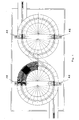
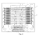
- a device for controlling the temperature of objects which are located in a mold 1, pallet or the like, has two hollow bodies 3 and 4 in a machine housing 2. Each hollow body 3 and 4 is surrounded by a guide 5 for guiding the molds 1, wherein the molds 1 via an inlet 6 in the guide 5.1 of the first cave body 3 arrive.
- the guides 5.1 and 5.2 orbit their respective hollow body 3 and 4 helically, as in Fig. 2 is recognizable.
- guide 5.1 leads a dash-dotted lines indicated straight line 7 in the upper region of the hollow body 3 for guiding 5.2 of the hollow body 4, wherein the guide 5.2 has a downwardly directed helix.
- the guide 5.2 then opens into an outlet 8.
- the hollow body 3/4 can according to Fig. 2 closed at the top of a lid or be open.
- a plurality of openings 10 are formed, which are also aligned helically upwards or downwards.
- the openings 10 follow the molds 1, which is located on the guide 5.1 / 5.2.
- a fan 11 which sucks air from the interior of the hollow body 3/4.
- This fan 11 is followed by a tempering 12, wherein the tempering 12 is formed as a heat exchanger and an inner tempering zone 13 and an outer tempering zone 14, which are respectively flowed through by a part of the cooling circuit.
- a liquid catcher 15 in which a baffle mat 16 is provided.
- the guide 5.1 / 5.2 shows according to Fig. 4 a helical track 18, which surrounds the hollow body 3 and 4.
- a helical track 18 which surrounds the hollow body 3 and 4.
- two drive wheels 19.1 and 19.2 supported by bearings 20, wherein the drive wheels 19.1 and 19.2 are engaged with each other.
- the drive wheel 19.1 is connected via an intermediate 20 with a drive wheel 21.
- the drive wheel 21 is seated on a drive shaft 22, wherein as in Fig. 2 recognizable the drive shaft 22 drives a plurality of drive wheels 21 in the different floors of the guide 5.1 and 5.2 respectively.
- the drive wheels 19.1 and 19.2 each have an axis A and B, by which they rotate. On each axis A and B also sits on a gear 23.1 and 23.2, which cooperate with a toothing 24.1 and 24.2 on a slider 25.
- the toothings 24.1 and 24.2 are matched to their toothed wheels 23.1 and 23.2 in a curvature such that an involute-type engagement between toothing 24.1 or 24.2 and toothed wheel 23.1 and 23.2 takes place.
- the slider 25 slides in a rail 26 which is disposed above the helical track 18, but this follows.
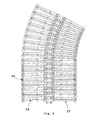
- the slider 25 is part of a support rocker 27, the in Fig. 3 is better recognizable.
- a plurality of support wings 27 are hinged together and thus form a transport path for the mold 1.
- the mold is not seated directly on a rocker surface 28, but on a transverse rib 29, which rises from the rocker surface 28.
- each side limiter 30.1 or 30.2 which, as in Fig. 5 recognizable, have the shape of a flat lying Z. This ensures that the lateral limiters 30 overlap with a linear guide and thus form a closed lateral boundary for the mold 1.
- the side delimiters 30 can diverge apart, but then overlap again in a straight line.
- the fan 11 sucks the air, as indicated by the arrows, from the interior of the hollow body 3/4 and presses the air through the tempering 12.
- the hollow body 3/4 is closed at the top, entseht in the hollow body, a negative pressure and in the entire machine housing 2 a corresponding overpressure.
- the negative pressure in the hollow body 3/4 air is sucked through the openings 10, so that a considerable, later to be described air circulation in the individual floors of the guide 5.1 / 5.2 arises.
- the tempering element has the inner tempering zone 13 and the outer tempering zone 14.
- the inner tempering zone 13 is charged with a coolant which has the lowest possible temperature, but not below 0 ° C.
- the cooling temperature of the outer tempering zone 14 is higher. This means that the water content of the cooling air condenses in particular at the inner tempering zone 13.
- the responsible for the cooling air part of the tempering works at a higher level.
- the liquid catcher 15 with its baffle mat 16 is arranged between the collecting trough 17 and the tempering element 12.
- This baffle mat collects the small droplets of condensed water, with the droplets seeping through the baffle mat.
- Most of the air exiting from the tempering 12 flows laterally past the liquid catcher 15 and takes with it no more liquid, since it seeps into the baffle mat. Only a minor part of the air penetrates the baffle mat, but is considerably slowed down here, so that this air flow no longer has the force that collects in the baffle mat to take heavy droplets and carry. These heavy drops drip down into the drip pan 17. That is, with the inventive concept is achieved that the cooling air dries to the desired dew point.
- the dried air is now guided laterally back on the walls of the machine housing 2 along the guide 5.1 / 5.2 upwards and enters there into the individual floors of the guides 5.1 / 5.2.
- the cooling air can impinge on the bottom of the molds.
- This floor usually has a plurality of cavities, in which there is a considerable turbulence of the cooling air, since the cooling air also accumulates in front of the openings 10 of the jacket 9.
- These swirls are indicated by the corresponding arrows in Fig. 4A indicated. That is, by this arrangement, cooling air flows in the shape from above, from below and from both sides, resulting in perfect heat release.
- the cooling of the objects is also made uniform. This has a very positive effect on the quality of the items.
Landscapes
- Engineering & Computer Science (AREA)
- Chemical & Material Sciences (AREA)
- Life Sciences & Earth Sciences (AREA)
- Food Science & Technology (AREA)
- Polymers & Plastics (AREA)
- Thermal Sciences (AREA)
- Physics & Mathematics (AREA)
- Mechanical Engineering (AREA)
- Combustion & Propulsion (AREA)
- General Engineering & Computer Science (AREA)
- Moulds For Moulding Plastics Or The Like (AREA)
- Heat Treatment Of Steel (AREA)
- Confectionery (AREA)
- Bakery Products And Manufacturing Methods Therefor (AREA)
- Meat, Egg Or Seafood Products (AREA)
- Control Of Temperature (AREA)
- Crystals, And After-Treatments Of Crystals (AREA)
- Sampling And Sample Adjustment (AREA)
Claims (12)
- Dispositif pour la régulation de la température d'objets dans des moules (1), en particulier pour le refroidissement de biens de consommation dans le domaine de la confiserie, avec un corps creux (3, 4) avec des ouvertures (10) dans son manteau (9), qui est entouré par un guidage (5.1, 5.2) pour les objets, au moins un ventilateur (11) étant attribué au corps creux (3, 4) et au moins un élément de régulation de température (12) étant attribué à ce dernier, le guidage (5.1, 5.2) pour les objets étant constitué de plusieurs coulisses porteuses (27), qui sont reliées entre elles de façon articulée, caractérisé en ce qu'à partir d'au moins une coulisse porteuse, se dresse verticalement une branche transversale (29) ou un élément d'espacement, sur laquelle ou sur lequel repose un moule (1) avec des objets, si bien que les moules (1) ne reposent pas directement sur les coulisses porteuses (27), mais sont surélevés par rapport à celles-ci.
- Dispositif selon la revendication 1, caractérisé en ce qu'au moins certaines des coulisses portantes (27) comportent une délimitation unilatérale ou bilatérale (29) ou encore un guidage latéral pour le moule.
- Dispositif selon la revendication 1, caractérisé en ce que les délimitations latérales (30) comportent une bande latérale en forme de Z couche, ces bandes latérales étant superposées dans la position de guidage.
- Dispositif selon l'une des revendications 1 à 3, caractérisé en ce qu'une pièce de coulissement (25) se dresse verticalement sur au moins certaines des coulisses porteuses (27), tout en étant guidée dans un rail (26), dans lequel s'engage une dentée (23.1, 23.2) de chaque côté.
- Dispositif selon la revendication 4, caractérisé en ce qu'un engagement du genre Evolvent se produit entre la denture (24.1, 24.2) et les roues dentées (23.1, 23.2).
- Dispositif selon l'une des revendications 4 ou 5, caractérisé en ce qu'à chacune des roues dentées (23.1, 23.2) est attribuée une roue d'entraînement (19.1, 19.2), qui est montée sur le même axe (A, B) que sa roue dentée (23.1, 23.2), les deux roues d'entraînement (19.1, 19.2) engrenant l'une avec l'autre.
- Dispositif selon la revendication 4, caractérisé en ce qu'une roue d'entraînement (19.1) est relié à une roue motrice (21) sur un arbre d'entraînement (22) par le biais d'une roue intermédiaire (20).
- Dispositif selon la revendication 7, caractérisé en ce que plusieurs roues motrices (21) sont disposées sur l'arbre d'entraînement (22) à différents étages du guidage (5.1, 5.2).
- Procédé pour la régulation de la température d'objets, en particulier pour le refroidissement de biens de consommation dans le domaine de la confiserie, caractérisé en ce qu'un dispositif selon l'une des revendications 1 à 8 est utilisé, dans lequel le ventilateur (11) aspire de l'air à partir du corps creux (3, 4), cet air passant à travers l'élément de régulation de température (12), l'air étant ensuite déshumidifié, puis alimenté vers le guidage (5.1, 5.2) depuis l'extérieur.
- Procédé selon la revendication 9, caractérisé en ce que l'air est brassé dans le guidage (5.1, 5.2).
- Procédé selon l'une des revendications 9 ou 10, caractérisé en ce que l'air dans l'élément de régulation de température est régulé à différentes températures en fonction de la zone.
- Procédé selon l'une des revendications 9 à 11, caractérisé en ce que de l'eau de condensation est soufflé vers le bas à partir de l'élément de régulation de température (12) et envoyé sur un collecteur de liquide (15).
Applications Claiming Priority (2)
| Application Number | Priority Date | Filing Date | Title |
|---|---|---|---|
| DE2003117006 DE10317006B3 (de) | 2003-04-11 | 2003-04-11 | Vorrichtung zum Temperieren von Gegenständen |
| EP04724969A EP1613170B1 (fr) | 2003-04-11 | 2004-04-01 | Dispositif destine a temperer des articles |
Related Parent Applications (1)
| Application Number | Title | Priority Date | Filing Date |
|---|---|---|---|
| EP04724969A Division EP1613170B1 (fr) | 2003-04-11 | 2004-04-01 | Dispositif destine a temperer des articles |
Publications (2)
| Publication Number | Publication Date |
|---|---|
| EP1757192A1 EP1757192A1 (fr) | 2007-02-28 |
| EP1757192B1 true EP1757192B1 (fr) | 2009-06-03 |
Family
ID=33154192
Family Applications (3)
| Application Number | Title | Priority Date | Filing Date |
|---|---|---|---|
| EP06017035A Expired - Lifetime EP1759592B1 (fr) | 2003-04-11 | 2004-04-01 | Dispositif pour tempérer des articles |
| EP04724969A Expired - Lifetime EP1613170B1 (fr) | 2003-04-11 | 2004-04-01 | Dispositif destine a temperer des articles |
| EP06017036A Expired - Lifetime EP1757192B1 (fr) | 2003-04-11 | 2004-04-01 | Dispositif et procédé destiné a tempérer des articles |
Family Applications Before (2)
| Application Number | Title | Priority Date | Filing Date |
|---|---|---|---|
| EP06017035A Expired - Lifetime EP1759592B1 (fr) | 2003-04-11 | 2004-04-01 | Dispositif pour tempérer des articles |
| EP04724969A Expired - Lifetime EP1613170B1 (fr) | 2003-04-11 | 2004-04-01 | Dispositif destine a temperer des articles |
Country Status (6)
| Country | Link |
|---|---|
| EP (3) | EP1759592B1 (fr) |
| AT (3) | ATE405172T1 (fr) |
| DE (4) | DE10362003B4 (fr) |
| DK (2) | DK1759592T3 (fr) |
| ES (2) | ES2311815T3 (fr) |
| WO (1) | WO2004089101A2 (fr) |
Families Citing this family (4)
| Publication number | Priority date | Publication date | Assignee | Title |
|---|---|---|---|---|
| GB2489255A (en) | 2011-03-22 | 2012-09-26 | Cadbury Uk Ltd | Confectionery processing machine |
| CN104110934B (zh) * | 2014-07-07 | 2018-08-14 | 安徽康佳同创电器有限公司 | 一种冰箱 |
| EP3755506B1 (fr) * | 2018-02-20 | 2022-05-18 | KNOBEL, Guido | Installation pour produire un produit comestible |
| EP3797600B1 (fr) * | 2019-09-30 | 2024-02-28 | KNOBEL, Guido | Dispositif de mise en température d'un produit de consommation |
Family Cites Families (10)
| Publication number | Priority date | Publication date | Assignee | Title |
|---|---|---|---|---|
| DE1083284B (de) * | 1958-12-22 | 1960-06-15 | Bahlsen Werner | Verfahren und Vorrichtung zur Verhinderung der Dampfkondensation auf den Abschirmflaechen von Kuehlsystemen |
| GB951793A (en) * | 1960-09-12 | 1964-03-11 | Weston Biscuit Company Wales L | Improvements in or relating to the cooling tunnels for articles having at least a part thereof in flowable or semi-flowable form |
| US3150504A (en) * | 1961-09-23 | 1964-09-29 | Lindt & Spruengli Schokolade | Cooling apparatus |
| GB1283073A (en) * | 1969-05-22 | 1972-07-26 | George Meagher | Improvements in or relating to cooling tunnels |
| JPS51142144A (en) * | 1975-05-31 | 1976-12-07 | Hirofumi Onodera | Swirl transport cooling machine |
| US4078394A (en) * | 1976-06-29 | 1978-03-14 | J. W. Greer, Inc. | Cryogenic freezer |
| SE436491B (sv) * | 1982-06-22 | 1984-12-17 | Frigoscandia Contracting Ab | Anordning for luftbehandling av produkter |
| GB8801530D0 (en) * | 1988-01-23 | 1988-02-24 | Dollar Rae Ltd | Control of atmospheric conditions |
| US4875343A (en) * | 1988-03-14 | 1989-10-24 | Jeppsson E Hakan O | Climate chamber with conveyor |
| DE19732037C2 (de) * | 1997-07-25 | 2002-08-08 | Kmb Produktions Ag Felben | Vorrichtung zum Kühlen von Verzehrgütern in der Confiserie |
-
2003
- 2003-04-11 DE DE10362003A patent/DE10362003B4/de not_active Withdrawn - After Issue
-
2004
- 2004-04-01 ES ES04724969T patent/ES2311815T3/es not_active Expired - Lifetime
- 2004-04-01 AT AT06017035T patent/ATE405172T1/de not_active IP Right Cessation
- 2004-04-01 DK DK06017035T patent/DK1759592T3/da active
- 2004-04-01 ES ES06017035T patent/ES2312069T3/es not_active Expired - Lifetime
- 2004-04-01 DE DE502004007891T patent/DE502004007891D1/de not_active Expired - Lifetime
- 2004-04-01 EP EP06017035A patent/EP1759592B1/fr not_active Expired - Lifetime
- 2004-04-01 WO PCT/CH2004/000203 patent/WO2004089101A2/fr not_active Ceased
- 2004-04-01 EP EP04724969A patent/EP1613170B1/fr not_active Expired - Lifetime
- 2004-04-01 AT AT06017036T patent/ATE432617T1/de not_active IP Right Cessation
- 2004-04-01 AT AT04724969T patent/ATE405171T1/de not_active IP Right Cessation
- 2004-04-01 EP EP06017036A patent/EP1757192B1/fr not_active Expired - Lifetime
- 2004-04-01 DE DE502004009583T patent/DE502004009583D1/de not_active Expired - Lifetime
- 2004-04-01 DE DE502004007931T patent/DE502004007931D1/de not_active Expired - Lifetime
- 2004-04-01 DK DK04724969T patent/DK1613170T3/da active
Also Published As
| Publication number | Publication date |
|---|---|
| ATE405171T1 (de) | 2008-09-15 |
| ATE405172T1 (de) | 2008-09-15 |
| DK1613170T3 (da) | 2008-12-08 |
| DK1759592T3 (da) | 2008-12-08 |
| EP1613170B1 (fr) | 2008-08-20 |
| DE10362003B4 (de) | 2007-04-05 |
| EP1757192A1 (fr) | 2007-02-28 |
| WO2004089101A2 (fr) | 2004-10-21 |
| ES2311815T3 (es) | 2009-02-16 |
| ATE432617T1 (de) | 2009-06-15 |
| WO2004089101A3 (fr) | 2005-02-03 |
| EP1613170A2 (fr) | 2006-01-11 |
| ES2312069T3 (es) | 2009-02-16 |
| DE10362003A1 (de) | 2005-01-20 |
| EP1759592A1 (fr) | 2007-03-07 |
| DE502004007891D1 (de) | 2008-10-02 |
| EP1759592B1 (fr) | 2008-08-20 |
| DE502004007931D1 (de) | 2008-10-02 |
| DE502004009583D1 (de) | 2009-07-16 |
Similar Documents
| Publication | Publication Date | Title |
|---|---|---|
| DE1596520C3 (de) | Verfahren und Vorrichtung zum Biegen und Härten von Glasscheiben | |
| DE1809859C3 (de) | Verfahren zum Härten von flachen Glasscheiben und Vorrichtung zur Durchführung des Verfahrens | |
| DE68908614T2 (de) | Vorrichtung zur Herstellung von gebogenen Glasscheiben. | |
| EP1757192B1 (fr) | Dispositif et procédé destiné a tempérer des articles | |
| DE102007062448A1 (de) | Verfahren zum Betreiben eines Temperierkanals für Süßwarenstücke sowie Temperierkanal | |
| DE1771383B2 (de) | Verfahren und Einrichtung zum kontinuierlichen Herstellen eines ununterbrochenen Schaumglasbandes | |
| EP3374099B1 (fr) | Procédé et dispositif de nettoyage de tampon à bandes | |
| DE1556704C3 (fr) | ||
| EP1011345B1 (fr) | Dispositif pour refroidir et/ou rechauffer des objets | |
| DE69310986T2 (de) | Vorrichtung und Verfahren zur kontinuierlichen Behandlung von Produkten | |
| DD212414A1 (de) | Kuehlkanal fuer mit schokoladenmasse oder aehnlichen massen ueberzogene artikel | |
| EP1050217A2 (fr) | Dispositif pour l'enrobage des articles | |
| DE3433433C1 (de) | Vorrichtung zum Erwaermen oder Kuehlen von metallischem Gut | |
| DE2520428C2 (de) | Fördereinrichtung für Verpackungsgüter | |
| DE2403776C2 (de) | Vorrichtung zur Herstellung eines Schaumkunststoffstranges | |
| DE10317006B3 (de) | Vorrichtung zum Temperieren von Gegenständen | |
| DE3420206A1 (de) | Vorrichtung zum ueberziehen von suesswarenartikeln | |
| DD211938A5 (de) | Verfahren und vorrichtung zum trocknen keramischer formlinge | |
| DE2053265A1 (de) | Matenalbehandlungsvorrichtung | |
| DE69407857T2 (de) | Kühleinheit für pastenförmige Produkte in Strangform | |
| DE10392950B4 (de) | Vorrichtung zum Herstellen eines Verzehrgutes | |
| WO2015169503A1 (fr) | Dispositif de formation d'une barre uniforme de produit alimentaire | |
| DE2043880A1 (de) | Verfahren zur Wärmebehandlung von auf der Oberflache mit z B Farbe, Lack od dgl behandelten Gegenstanden, insbesondere aus Holz, und Vorrichtung zur Durchfuhrung des Verfahrens | |
| DE2551333A1 (de) | Vorrichtung zur herstellung eines strangfoermigen koerpers aus schaumkunststoff | |
| DE19514917A1 (de) | Vorrichtung zum Luftkühlen von mit flüssiger Schokolade oder Fettglasuren überzogenen Nahrungsmitteln |
Legal Events
| Date | Code | Title | Description |
|---|---|---|---|
| PUAI | Public reference made under article 153(3) epc to a published international application that has entered the european phase |
Free format text: ORIGINAL CODE: 0009012 |
|
| 17P | Request for examination filed |
Effective date: 20060816 |
|
| AC | Divisional application: reference to earlier application |
Ref document number: 1613170 Country of ref document: EP Kind code of ref document: P |
|
| AK | Designated contracting states |
Kind code of ref document: A1 Designated state(s): AT BE BG CH CY CZ DE DK EE ES FI FR GB GR HU IE IT LI LU MC NL PL PT RO SE SI SK TR |
|
| 17Q | First examination report despatched |
Effective date: 20070601 |
|
| AKX | Designation fees paid |
Designated state(s): AT BE BG CH CY CZ DE DK EE ES FI FR GB GR HU IE IT LI LU MC NL PL PT RO SE SI SK TR |
|
| GRAP | Despatch of communication of intention to grant a patent |
Free format text: ORIGINAL CODE: EPIDOSNIGR1 |
|
| RTI1 | Title (correction) |
Free format text: DEVICE AND METHOD FOR TEMPERING OBJECTS |
|
| GRAS | Grant fee paid |
Free format text: ORIGINAL CODE: EPIDOSNIGR3 |
|
| GRAA | (expected) grant |
Free format text: ORIGINAL CODE: 0009210 |
|
| AC | Divisional application: reference to earlier application |
Ref document number: 1613170 Country of ref document: EP Kind code of ref document: P |
|
| AK | Designated contracting states |
Kind code of ref document: B1 Designated state(s): AT BE BG CH CY CZ DE DK EE ES FI FR GB GR HU IE IT LI LU MC NL PL PT RO SE SI SK TR |
|
| REG | Reference to a national code |
Ref country code: GB Ref legal event code: FG4D Free format text: NOT ENGLISH |
|
| REG | Reference to a national code |
Ref country code: CH Ref legal event code: EP |
|
| REG | Reference to a national code |
Ref country code: IE Ref legal event code: FG4D Free format text: LANGUAGE OF EP DOCUMENT: GERMAN |
|
| REF | Corresponds to: |
Ref document number: 502004009583 Country of ref document: DE Date of ref document: 20090716 Kind code of ref document: P |
|
| REG | Reference to a national code |
Ref country code: CH Ref legal event code: NV Representative=s name: SCHNEIDER FELDMANN AG PATENT- UND MARKENANWAELTE |
|
| PG25 | Lapsed in a contracting state [announced via postgrant information from national office to epo] |
Ref country code: FI Free format text: LAPSE BECAUSE OF FAILURE TO SUBMIT A TRANSLATION OF THE DESCRIPTION OR TO PAY THE FEE WITHIN THE PRESCRIBED TIME-LIMIT Effective date: 20090603 |
|
| NLV1 | Nl: lapsed or annulled due to failure to fulfill the requirements of art. 29p and 29m of the patents act | ||
| PG25 | Lapsed in a contracting state [announced via postgrant information from national office to epo] |
Ref country code: NL Free format text: LAPSE BECAUSE OF FAILURE TO SUBMIT A TRANSLATION OF THE DESCRIPTION OR TO PAY THE FEE WITHIN THE PRESCRIBED TIME-LIMIT Effective date: 20090603 Ref country code: PL Free format text: LAPSE BECAUSE OF FAILURE TO SUBMIT A TRANSLATION OF THE DESCRIPTION OR TO PAY THE FEE WITHIN THE PRESCRIBED TIME-LIMIT Effective date: 20090603 Ref country code: SI Free format text: LAPSE BECAUSE OF FAILURE TO SUBMIT A TRANSLATION OF THE DESCRIPTION OR TO PAY THE FEE WITHIN THE PRESCRIBED TIME-LIMIT Effective date: 20090603 Ref country code: SE Free format text: LAPSE BECAUSE OF FAILURE TO SUBMIT A TRANSLATION OF THE DESCRIPTION OR TO PAY THE FEE WITHIN THE PRESCRIBED TIME-LIMIT Effective date: 20090903 |
|
| REG | Reference to a national code |
Ref country code: IE Ref legal event code: FD4D |
|
| PG25 | Lapsed in a contracting state [announced via postgrant information from national office to epo] |
Ref country code: RO Free format text: LAPSE BECAUSE OF FAILURE TO SUBMIT A TRANSLATION OF THE DESCRIPTION OR TO PAY THE FEE WITHIN THE PRESCRIBED TIME-LIMIT Effective date: 20090603 Ref country code: IE Free format text: LAPSE BECAUSE OF FAILURE TO SUBMIT A TRANSLATION OF THE DESCRIPTION OR TO PAY THE FEE WITHIN THE PRESCRIBED TIME-LIMIT Effective date: 20090603 Ref country code: ES Free format text: LAPSE BECAUSE OF FAILURE TO SUBMIT A TRANSLATION OF THE DESCRIPTION OR TO PAY THE FEE WITHIN THE PRESCRIBED TIME-LIMIT Effective date: 20090914 Ref country code: EE Free format text: LAPSE BECAUSE OF FAILURE TO SUBMIT A TRANSLATION OF THE DESCRIPTION OR TO PAY THE FEE WITHIN THE PRESCRIBED TIME-LIMIT Effective date: 20090603 Ref country code: CZ Free format text: LAPSE BECAUSE OF FAILURE TO SUBMIT A TRANSLATION OF THE DESCRIPTION OR TO PAY THE FEE WITHIN THE PRESCRIBED TIME-LIMIT Effective date: 20090603 |
|
| PG25 | Lapsed in a contracting state [announced via postgrant information from national office to epo] |
Ref country code: SK Free format text: LAPSE BECAUSE OF FAILURE TO SUBMIT A TRANSLATION OF THE DESCRIPTION OR TO PAY THE FEE WITHIN THE PRESCRIBED TIME-LIMIT Effective date: 20090603 |
|
| PG25 | Lapsed in a contracting state [announced via postgrant information from national office to epo] |
Ref country code: PT Free format text: LAPSE BECAUSE OF FAILURE TO SUBMIT A TRANSLATION OF THE DESCRIPTION OR TO PAY THE FEE WITHIN THE PRESCRIBED TIME-LIMIT Effective date: 20091003 Ref country code: BG Free format text: LAPSE BECAUSE OF FAILURE TO SUBMIT A TRANSLATION OF THE DESCRIPTION OR TO PAY THE FEE WITHIN THE PRESCRIBED TIME-LIMIT Effective date: 20090903 |
|
| PLBE | No opposition filed within time limit |
Free format text: ORIGINAL CODE: 0009261 |
|
| STAA | Information on the status of an ep patent application or granted ep patent |
Free format text: STATUS: NO OPPOSITION FILED WITHIN TIME LIMIT |
|
| PG25 | Lapsed in a contracting state [announced via postgrant information from national office to epo] |
Ref country code: DK Free format text: LAPSE BECAUSE OF FAILURE TO SUBMIT A TRANSLATION OF THE DESCRIPTION OR TO PAY THE FEE WITHIN THE PRESCRIBED TIME-LIMIT Effective date: 20090603 |
|
| 26N | No opposition filed |
Effective date: 20100304 |
|
| PG25 | Lapsed in a contracting state [announced via postgrant information from national office to epo] |
Ref country code: GR Free format text: LAPSE BECAUSE OF FAILURE TO SUBMIT A TRANSLATION OF THE DESCRIPTION OR TO PAY THE FEE WITHIN THE PRESCRIBED TIME-LIMIT Effective date: 20090904 |
|
| PG25 | Lapsed in a contracting state [announced via postgrant information from national office to epo] |
Ref country code: MC Free format text: LAPSE BECAUSE OF NON-PAYMENT OF DUE FEES Effective date: 20100430 |
|
| GBPC | Gb: european patent ceased through non-payment of renewal fee |
Effective date: 20100401 |
|
| REG | Reference to a national code |
Ref country code: FR Ref legal event code: ST Effective date: 20101230 |
|
| PG25 | Lapsed in a contracting state [announced via postgrant information from national office to epo] |
Ref country code: IT Free format text: LAPSE BECAUSE OF FAILURE TO SUBMIT A TRANSLATION OF THE DESCRIPTION OR TO PAY THE FEE WITHIN THE PRESCRIBED TIME-LIMIT Effective date: 20090603 Ref country code: GB Free format text: LAPSE BECAUSE OF NON-PAYMENT OF DUE FEES Effective date: 20100401 |
|
| PG25 | Lapsed in a contracting state [announced via postgrant information from national office to epo] |
Ref country code: AT Free format text: LAPSE BECAUSE OF NON-PAYMENT OF DUE FEES Effective date: 20100401 |
|
| PG25 | Lapsed in a contracting state [announced via postgrant information from national office to epo] |
Ref country code: FR Free format text: LAPSE BECAUSE OF NON-PAYMENT OF DUE FEES Effective date: 20100430 |
|
| PG25 | Lapsed in a contracting state [announced via postgrant information from national office to epo] |
Ref country code: CY Free format text: LAPSE BECAUSE OF FAILURE TO SUBMIT A TRANSLATION OF THE DESCRIPTION OR TO PAY THE FEE WITHIN THE PRESCRIBED TIME-LIMIT Effective date: 20090603 |
|
| PG25 | Lapsed in a contracting state [announced via postgrant information from national office to epo] |
Ref country code: HU Free format text: LAPSE BECAUSE OF FAILURE TO SUBMIT A TRANSLATION OF THE DESCRIPTION OR TO PAY THE FEE WITHIN THE PRESCRIBED TIME-LIMIT Effective date: 20091204 Ref country code: LU Free format text: LAPSE BECAUSE OF NON-PAYMENT OF DUE FEES Effective date: 20100401 |
|
| PG25 | Lapsed in a contracting state [announced via postgrant information from national office to epo] |
Ref country code: TR Free format text: LAPSE BECAUSE OF FAILURE TO SUBMIT A TRANSLATION OF THE DESCRIPTION OR TO PAY THE FEE WITHIN THE PRESCRIBED TIME-LIMIT Effective date: 20090603 |
|
| PGFP | Annual fee paid to national office [announced via postgrant information from national office to epo] |
Ref country code: DE Payment date: 20140417 Year of fee payment: 11 |
|
| REG | Reference to a national code |
Ref country code: DE Ref legal event code: R119 Ref document number: 502004009583 Country of ref document: DE |
|
| PG25 | Lapsed in a contracting state [announced via postgrant information from national office to epo] |
Ref country code: DE Free format text: LAPSE BECAUSE OF NON-PAYMENT OF DUE FEES Effective date: 20151103 |
|
| REG | Reference to a national code |
Ref country code: CH Ref legal event code: PCOW Free format text: NEW ADDRESS: BRUEEL 11, 8526 OBERNEUNFORN (CH) |
|
| PGFP | Annual fee paid to national office [announced via postgrant information from national office to epo] |
Ref country code: BE Payment date: 20200316 Year of fee payment: 17 |
|
| REG | Reference to a national code |
Ref country code: CH Ref legal event code: PFA Owner name: AWEMA AG, CH Free format text: FORMER OWNER: AWEMA AG, CH |
|
| PGFP | Annual fee paid to national office [announced via postgrant information from national office to epo] |
Ref country code: CH Payment date: 20200727 Year of fee payment: 17 |
|
| REG | Reference to a national code |
Ref country code: BE Ref legal event code: MM Effective date: 20210430 |
|
| PG25 | Lapsed in a contracting state [announced via postgrant information from national office to epo] |
Ref country code: LI Free format text: LAPSE BECAUSE OF NON-PAYMENT OF DUE FEES Effective date: 20210430 Ref country code: CH Free format text: LAPSE BECAUSE OF NON-PAYMENT OF DUE FEES Effective date: 20210430 |
|
| PG25 | Lapsed in a contracting state [announced via postgrant information from national office to epo] |
Ref country code: BE Free format text: LAPSE BECAUSE OF NON-PAYMENT OF DUE FEES Effective date: 20210430 |