EP1757434A2 - Cantre remplaçable dans une machine pour l'application de fibes - Google Patents
Cantre remplaçable dans une machine pour l'application de fibes Download PDFInfo
- Publication number
- EP1757434A2 EP1757434A2 EP06119545A EP06119545A EP1757434A2 EP 1757434 A2 EP1757434 A2 EP 1757434A2 EP 06119545 A EP06119545 A EP 06119545A EP 06119545 A EP06119545 A EP 06119545A EP 1757434 A2 EP1757434 A2 EP 1757434A2
- Authority
- EP
- European Patent Office
- Prior art keywords
- fiber
- creel
- auto
- placement machine
- fiber placement
- Prior art date
- Legal status (The legal status is an assumption and is not a legal conclusion. Google has not performed a legal analysis and makes no representation as to the accuracy of the status listed.)
- Granted
Links
- 239000000835 fiber Substances 0.000 title claims abstract description 408
- 238000000034 method Methods 0.000 claims abstract description 166
- 239000000463 material Substances 0.000 claims abstract description 26
- 230000008569 process Effects 0.000 claims description 78
- 238000003466 welding Methods 0.000 claims description 48
- 238000009966 trimming Methods 0.000 claims description 26
- 230000000977 initiatory effect Effects 0.000 claims description 9
- 239000002131 composite material Substances 0.000 description 6
- 238000001816 cooling Methods 0.000 description 6
- 238000009727 automated fiber placement Methods 0.000 description 4
- 238000003860 storage Methods 0.000 description 3
- 230000008901 benefit Effects 0.000 description 2
- 230000008859 change Effects 0.000 description 2
- 238000003780 insertion Methods 0.000 description 2
- 230000037431 insertion Effects 0.000 description 2
- 238000004519 manufacturing process Methods 0.000 description 2
- 230000004048 modification Effects 0.000 description 2
- 238000012986 modification Methods 0.000 description 2
- 229920000049 Carbon (fiber) Polymers 0.000 description 1
- 230000004913 activation Effects 0.000 description 1
- 239000004760 aramid Substances 0.000 description 1
- 229920006231 aramid fiber Polymers 0.000 description 1
- 239000004917 carbon fiber Substances 0.000 description 1
- 230000006835 compression Effects 0.000 description 1
- 238000007906 compression Methods 0.000 description 1
- 238000010276 construction Methods 0.000 description 1
- 239000011152 fibreglass Substances 0.000 description 1
- 238000010438 heat treatment Methods 0.000 description 1
- 230000007246 mechanism Effects 0.000 description 1
- VNWKTOKETHGBQD-UHFFFAOYSA-N methane Chemical compound C VNWKTOKETHGBQD-UHFFFAOYSA-N 0.000 description 1
- 239000011347 resin Substances 0.000 description 1
- 229920005989 resin Polymers 0.000 description 1
- 230000004044 response Effects 0.000 description 1
- 230000001960 triggered effect Effects 0.000 description 1
- 238000004804 winding Methods 0.000 description 1
Images


Classifications
-
- B—PERFORMING OPERATIONS; TRANSPORTING
- B29—WORKING OF PLASTICS; WORKING OF SUBSTANCES IN A PLASTIC STATE IN GENERAL
- B29C—SHAPING OR JOINING OF PLASTICS; SHAPING OF MATERIAL IN A PLASTIC STATE, NOT OTHERWISE PROVIDED FOR; AFTER-TREATMENT OF THE SHAPED PRODUCTS, e.g. REPAIRING
- B29C70/00—Shaping composites, i.e. plastics material comprising reinforcements, fillers or preformed parts, e.g. inserts
- B29C70/04—Shaping composites, i.e. plastics material comprising reinforcements, fillers or preformed parts, e.g. inserts comprising reinforcements only, e.g. self-reinforcing plastics
- B29C70/28—Shaping operations therefor
- B29C70/30—Shaping by lay-up, i.e. applying fibres, tape or broadsheet on a mould, former or core; Shaping by spray-up, i.e. spraying of fibres on a mould, former or core
- B29C70/38—Automated lay-up, e.g. using robots, laying filaments according to predetermined patterns
- B29C70/382—Automated fiber placement [AFP]
-
- B—PERFORMING OPERATIONS; TRANSPORTING
- B29—WORKING OF PLASTICS; WORKING OF SUBSTANCES IN A PLASTIC STATE IN GENERAL
- B29C—SHAPING OR JOINING OF PLASTICS; SHAPING OF MATERIAL IN A PLASTIC STATE, NOT OTHERWISE PROVIDED FOR; AFTER-TREATMENT OF THE SHAPED PRODUCTS, e.g. REPAIRING
- B29C53/00—Shaping by bending, folding, twisting, straightening or flattening; Apparatus therefor
- B29C53/80—Component parts, details or accessories; Auxiliary operations
- B29C53/8008—Component parts, details or accessories; Auxiliary operations specially adapted for winding and joining
- B29C53/8016—Storing, feeding or applying winding materials, e.g. reels, thread guides, tensioners
-
- B—PERFORMING OPERATIONS; TRANSPORTING
- B29—WORKING OF PLASTICS; WORKING OF SUBSTANCES IN A PLASTIC STATE IN GENERAL
- B29C—SHAPING OR JOINING OF PLASTICS; SHAPING OF MATERIAL IN A PLASTIC STATE, NOT OTHERWISE PROVIDED FOR; AFTER-TREATMENT OF THE SHAPED PRODUCTS, e.g. REPAIRING
- B29C53/00—Shaping by bending, folding, twisting, straightening or flattening; Apparatus therefor
- B29C53/80—Component parts, details or accessories; Auxiliary operations
- B29C53/82—Cores or mandrels
- B29C53/821—Mandrels especially adapted for winding and joining
- B29C53/825—Mandrels especially adapted for winding and joining for continuous winding
- B29C53/827—Mandrels especially adapted for winding and joining for continuous winding formed by several elements rotating about their own axes
-
- B—PERFORMING OPERATIONS; TRANSPORTING
- B65—CONVEYING; PACKING; STORING; HANDLING THIN OR FILAMENTARY MATERIAL
- B65H—HANDLING THIN OR FILAMENTARY MATERIAL, e.g. SHEETS, WEBS, CABLES
- B65H49/00—Unwinding or paying-out filamentary material; Supporting, storing or transporting packages from which filamentary material is to be withdrawn or paid-out
- B65H49/18—Methods or apparatus in which packages rotate
- B65H49/20—Package-supporting devices
- B65H49/32—Stands or frameworks
-
- B—PERFORMING OPERATIONS; TRANSPORTING
- B65—CONVEYING; PACKING; STORING; HANDLING THIN OR FILAMENTARY MATERIAL
- B65H—HANDLING THIN OR FILAMENTARY MATERIAL, e.g. SHEETS, WEBS, CABLES
- B65H67/00—Replacing or removing cores, receptacles, or completed packages at paying-out, winding, or depositing stations
- B65H67/02—Arrangements for removing spent cores or receptacles and replacing by supply packages at paying-out stations
-
- B—PERFORMING OPERATIONS; TRANSPORTING
- B65—CONVEYING; PACKING; STORING; HANDLING THIN OR FILAMENTARY MATERIAL
- B65H—HANDLING THIN OR FILAMENTARY MATERIAL, e.g. SHEETS, WEBS, CABLES
- B65H2701/00—Handled material; Storage means
- B65H2701/30—Handled filamentary material
- B65H2701/31—Textiles threads or artificial strands of filaments
-
- Y—GENERAL TAGGING OF NEW TECHNOLOGICAL DEVELOPMENTS; GENERAL TAGGING OF CROSS-SECTIONAL TECHNOLOGIES SPANNING OVER SEVERAL SECTIONS OF THE IPC; TECHNICAL SUBJECTS COVERED BY FORMER USPC CROSS-REFERENCE ART COLLECTIONS [XRACs] AND DIGESTS
- Y10—TECHNICAL SUBJECTS COVERED BY FORMER USPC
- Y10T—TECHNICAL SUBJECTS COVERED BY FORMER US CLASSIFICATION
- Y10T156/00—Adhesive bonding and miscellaneous chemical manufacture
- Y10T156/10—Methods of surface bonding and/or assembly therefor
- Y10T156/1052—Methods of surface bonding and/or assembly therefor with cutting, punching, tearing or severing
- Y10T156/1062—Prior to assembly
- Y10T156/1066—Cutting to shape joining edge surfaces only
Definitions
- This invention relates to the forming of composite structures with automated fiber placement machines, and more particularly to fiber placement machines utilizing creels for storage of spools of tows of material for use in forming the composite structure.
- Automated fiber placement machines are widely used to manufacture parts, components and structures from composite material.
- the materials used in automated fiber placement are typically composed of longitudinal fibers and resin consolidated into tapes, or thin strips, commonly known as "tows.”
- Individual tapes or tows are manipulated by the fiber placement machine to form a band of material that is deposited onto a tool.
- Parts are built up layer-by-layer, with tapes or tows of composite material, with the angle at which each layer "ply” is laid onto the tool being precisely determined by the fiber placement machine.
- Automated fiber placement enables the construction of complex composite structures having steered or curvilinear fiber paths. This method of producing composite structures is more cost effective than manual methods. It provides an improved structural efficiency due to its ability to orient the fibers along local internal loads paths, which potentially results in lighter structures and lower costs than in structures made by other production methods.
- the individual tows of material are typically wound onto spools, stored in an environmentally-controlled structure known as a creel.
- a single creel may commonly include, for example, provisions for storage and simultaneous outfeed from 32 spools.
- the tows stored on one or more of the spools may be completely used up, prior to completion of the part.
- An apparatus and method are provided for replacing a creel in a fiber placement machine, by sequentially moving replacement creels into place on tracks and/or guide rails, as one or more spools in a previously operating creel are exhausted, and removing the creel having the one or more exhausted spools, to thereby allow fiber placement to continue from the replacement creel while the creel having one or more exhausted spools of material is replenished.
- the invention also allows a convenient means of changing to a different material, or tows of different widths, etc., during the fiber placement process.
- an apparatus and/or method for replacing a creel in a fiber placement machine may also incorporate apparatuses and methods for accomplishing an auto-splice of the fiber tows as the creels are interchanged.
- a method for operating a fiber placement machine during a fiber placement process may include supporting a first replaceable creel in an alignment position, aligning the first replaceable creel with the fiber placement machine, and attaching the first replaceable creel to the fiber placement machine.
- the first creel may be supported in the alignment position at a creel exchange location, with the method further including, moving the fiber placement machine to the creel exchange location.
- the creel may be loaded and/or replenished while the creel is detached from the fiber placement machine.
- a method may include splicing the lead end of at least one of the second fiber tows with a corresponding tail end of at least one of the first fiber tows, using an auto-splice method.
- the auto-splice method may include assisting an operator in splicing the tail end of a first fiber tow to the lead end of the second fiber tow, by performing the splicing operation with an auto-splice apparatus having an operator actuated welding device for clamping together and applying heat to overlapped portions of the tail end of the first fiber tow and the lead end of the second fiber tow.
- the operator may initiate a first phase of the splicing process, performed by the auto-splice apparatus, in which the auto-splice apparatus sequentially clamps the tail end of the first tow extending from the fiber placement head, and trims the tail end of the first tow to a desired length to form a trimmed tail end of the first tow.
- the operator may then feed the lead end of the second tow into the auto-splice apparatus, with the auto-splice apparatus guiding the lead end into an overlapped position adjacent the trimmed tail end of the first fiber tow, to form overlapped portions of the first and second fiber tows.
- the operator may then initiate a second phase of the splicing process, performed by the auto-splice apparatus, in which the auto-splice apparatus welds together the overlapped portions of the first and second fiber tows, and then unclamps the tail end of the first fiber tow.
- Some forms of the invention may include, removing the first replaceable creel from the fiber placement machine by: aligning the first replaceable creel attached to the fiber placement machine with a creel support structure; supporting the first replaceable creel with the support structure; detaching the first replacement creel from the fiber placement machine; and moving the first replaceable creel out of alignment with the fiber placement machine.
- the support structure may be located at a creel exchange location, with the invention further including moving the fiber placement machine to the creel exchange location.
- the invention may further include replenishing the first creel while it is detached from the fiber placement machine.
- the invention may further include sequentially clamping a tail end of each of the first tows, extending from the fiber placement head, and severing the tail end of the first tow at a desired length thereof within the fiber placement machine, to form a trimmed tail end of the first fiber tow.
- the invention may include exchanging the first replaceable creel with a second replaceable creel by: aligning the first replaceable creel attached to the fiber placement machine with a creel support structure; supporting the first replaceable creel with the support structure; detaching the first replaceable creel from the fiber placement machine; moving the first replaceable creel out of alignment with the fiber placement machine; supporting a second replaceable creel in an alignment position; aligning the second replaceable creel with the fiber placement machine; and attaching the second replaceable creel to the fiber placement machine.
- the support structure may be located at a creel exchange location. Where the support structure is located at a creel exchange location, the invention may further include, moving the fiber placement machine to the creel exchange location.
- the invention may include moving the fiber placement machine to the creel exchange location.
- the first creel may be replenished while it is detached from the fiber placement machine.
- the fiber placement machine may be operated with the multiple second fiber tows being supplied from the second replaceable creel, while the first replaceable creel is detached.
- the invention may include exchanging the second creel for the first creel to replace the corresponding fiber tow in the first creel with at least one fiber tow of differing material or configuration, at a pre-determined point in the fiber placement process.
- the invention may include exchanging the second creel for the first creel, when at least one of the spools of fiber tows in the first creel has reached a low material condition.
- the first creel may then be replenished while it is detached from the fiber placement machine.
- the fiber placement machine has one or more first fiber tows therein, each having a tail end thereof and being supplied from a separate first reel of the first fiber tow located within the first creel
- the second replacement creel includes one or more second fiber tows therein, each having a lead end thereof and being supplied by a separate reel of second fiber tow located within the second creel
- the invention may include splicing the head end of at least one of the second fiber tows with a corresponding tail end of at least one of the first fiber tows, using an auto-splice method.
- the auto-splice method is performed with an auto-splice apparatus.
- the auto-splice apparatus may have a first half thereof, fixedly attached to the fiber placement machine for clamping and trimming the tail end of the first tow, and for welding the overlapped portions of the first and second tows.
- the auto-splice apparatus may have multiple second halves thereof, with one of the multiple second halves being fixedly attached to the first creel, and another of the multiple second halves being fixedly attached to the second creel.
- the first and second halves may be configured for clamping the respective lead ends of the first and second tows within the first and second creels respectively, when the first and second creels are not operatively connected to the fiber placement machine.
- the second halves may be further configured for feeding the lead ends of the first and second fiber tows, respectively, into the first half of the auto-splice apparatus, when the respective first or second creel is operatively attached to the fiber placement machine.
- a method may include clamping the respective lead ends of the first and second tows within the first and second creels respectively, when the first and second creels are not operatively connected to the fiber placement machine.
- a method may further include feeding the lead end of the second fiber tow into the first half of the auto-splice apparatus, with the second creel operatively attached to the fiber placement machine, to form overlapped portions of the lead end of the second tow and the tail end of the first tow.
- the overlapped portions of the first end second tows may then be welded together.
- the tail end of the first fiber tow may be unclamped after welding together the overlapped portions of the first and second fiber tows.
- the invention may further include, simultaneously clamping and trimming all of the first fiber tows, prior to detachment of the first creel from the fiber placement machine.
- An auto-splice method used in practicing the invention, may include assisting an operator in splicing the tail end of the first fiber tow to the lead end of the second fiber tow, by performing the splicing operation with an auto-splice apparatus, having an operator actuated welding device for clamping together and applying heat to overlapped portions of the tail end of the first fiber tow and the lead end of the second fiber tow.
- the auto-splice method may include, having the operator initiate a first phase of the splicing process, performed by the auto-splice apparatus, in which the auto-splice apparatus sequentially clamps the tail end of the first tow, extending from the fiber placement head, and trims the tail end of the first tow to a desired length to form a tail end of the first tow.
- the operator may then feed the lead end of the second tow into the auto-splice apparatus, with the auto-splice apparatus guiding the lead end into an overlapped position adjacent the trimmed tail end of the first fiber tow, to form overlapped portions of the first and second fiber tows.
- the operator may then initiate a second phase of the splicing process, performed by the auto-splice apparatus, in which the auto-splice apparatus welds together the overlapped portions of the first and second fiber tows, and then unclamps the tail end of the first fiber tow.
- An auto-splice apparatus for assisting an operator in performing a splicing process, according to the invention, may have a first half thereof, fixedly attached to the fiber placement machine for clamping and trimming the tail end of the first tow, and for welding the overlapped portions of the first and second tows.
- the auto-splice apparatus may have multiple second halves thereof, with one of the multiple second halves being fixedly attached to the first creel and another of the multiple second halves being fixedly attached to the second creel.
- the second halves may be configured for clamping the respective lead ends of the first and second tows within the first and second creels respectively, when the first and second creels are not operatively connected to the fiber placement machine.
- the second halves may be further configured for feeding the lead ends of the first and second fiber tows respectively into the first half of the auto-splice apparatus when the respective first or second creels are operatively attached to the fiber placement machine.
- a method, for assisting an operator in the splicing process may include clamping the respective lead ends of the first and second tows within the first and second creels respectively, when the first and second creels are not operatively connected to the fiber placement machine.
- the invention may also include feeding the lead end of the second fiber tow into the first half of the auto-splice apparatus, when the second creel is operatively attached to the fiber placement machine, and the second phase of the auto-splice process is initiated.
- the first phase of the splicing process may include simultaneously clamping and trimming all of the first fiber tows, prior to detachment of the first creel from the fiber placement machine.
- Some forms of the invention include an auto-splice apparatus, and a method for using an auto-splice apparatus, for assisting an operator in splicing the tail end of a first fiber tow to the lead end of a second fiber tow, where the first fiber tow is being fed from a first reel of the first fiber tow to a fiber placement head of a fiber placement machine, and the second fiber tow is being fed from a second reel of the second fiber tow, with the auto-splice apparatus including, an operator actuated welding device for clamping together and applying heat to overlapped portions of the tail end of the first fiber tow and the lead end of the second fiber tow.
- a method for assisting an operator in splicing the tail end of a first fiber tow to the lead end of a second fiber tow, using an auto-splice apparatus includes the operator initiating a first phase of the splicing process, performed by the auto-splice apparatus, in which the auto-splice apparatus sequentially clamps the tail end of the first tow extending from the fiber placement head, and trims the tail end of the first tow to a desired length to form a trimmed tail end of the first tow.
- the operator then feeds the lead end of the second tow into the auto-splice apparatus, with the auto-splice apparatus guiding the lead end into an overlapped position adjacent the trimmed tail end of the first fiber tow, to form overlapped portions of the first and second fiber tows.
- the operator then initiates a second phase of the splicing process, performed by the auto-splice apparatus, in which the auto-splice apparatus welds together the overlapped portions of the first and second tows, and then unclamps the tail end of the first fiber tow.
- a method may also include detecting a low material condition in the first reel of the fiber tow, and stopping the feed of the first fiber tow to the fiber placement head prior to initiating the first phase of the splicing process.
- the method may further include re-starting the feed of the trimmed tail end of the first fiber tow, having the second fiber tow welded thereto, to the fiber placement head, following completion of the second phase of the splicing process.
- a method may include having the operator replace the first reel with a second reel, by removing the first reel and operatively mounting the second reel within the creel in place of the first reel, between the first and second phases of the splicing process.
- a method may further include having the operator feed the lead end of the second fiber tow into the auto-splice apparatus, between the first and second phases of the splicing process.
- welding the overlapped portions of the first and second fiber tows together may include the steps of: clamping the overlapped portions of the first and second fiber tows together between a welding head and a support surface with a clamping pressure; applying heat to the overlapped portions with the welding head, for a period of time, to thereby weld the overlapped portions together; and, unclamping the overlapped portions following completion of the weld.
- the invention may further include controlling one or more of the clamping pressure, the heat applied by the welding head, and/or the period of time, to desired values thereof.
- Welding the overlapped portions of the first and second fiber tows together, according to the invention may also include cooling the overlapped portions subsequent to forming the weld.
- the invention may further include detaching the first creel from the fiber placement machine and operatively attaching the second creel to the fiber placement machine in place of the first creel.
- the invention may further include operating the fiber placement machine with a second fiber tow from the second creel, while the first creel is detached from the fiber placement machine.
- the invention may also include replenishing the first creel, with different first reels of first fiber tows, while the first creel is detached from the fiber placement machine.
- an auto-splice apparatus may have a first half thereof disposed within the fiber placement machine for clamping and trimming the tail end of the first tow, and for welding the overlapped portions of the first and second tows.
- the auto-splice apparatus may also have multiple second halves thereof, with one of the multiple second halves being disposed in the first creel and another of the multiple second halves being disposed in the second creel.
- the second halves may be configured for clamping the respective lead ends of the first and second tows within the first and second creels respectively, when the first and second creels are not operatively connected to the fiber placement machine.
- the second halves may be further configured for feeding the lead ends of the first and second fiber tows, respectively, into the first half of the auto-splice apparatus, when the respective first or second creel is operatively attached to the fiber placement machine.
- the respective lead ends of the first and second tows, within the first and second creels respectively, may be clamped by the second halves of the auto-splice apparatus, when the first and second creels are not operatively connected to the fiber placement machine.
- the second halves of the auto-splice apparatus may also feed the lead ends of the first and second fiber tows, respectively, into the first half of the auto-splice apparatus, when the respective first or second creel is operatively attached to the fiber placement machine, and the second phase of the auto-splice process is initiated.
- the first phase of the splicing process may include, simultaneously clamping and trimming all of the first fiber tows, prior to detachment of the first creel from the fiber placement machine.
- all of the first fiber tows may be sequentially clamped and trimmed, prior to detachment of the first creel from the fiber placement machine.
- a single auto-splice apparatus may be movable, between multiple tows fed from a creel, for performing the splicing process, according to the invention.
- One form of an auto-splice apparatus includes an operator actuated welding device, for clamping together and applying heat to overlapped portions of the tail end of the first fiber tow and the lead end of the second fiber tow.
- the auto-splice apparatus for assisting an operator in splicing the tail end of a first fiber tow to the lead end of a second fiber tow, wherein the first fiber tow is being fed from a first reel of the first fiber tow to a fiber placement head of the fiber placement machine, and the second fiber tow is being fed from a second reel of the second fiber tow
- the auto-splice apparatus may include a tail end clamping device, a tail end trimming device, a welding device, and a two-position operator activated control element operatively connecting the tail end clamping device, the tail end trimming device, and the welding device.
- the tail end clamping device, the tail end trimming device, the welding device, and the two-position operator activated control element may be operatively disposed and interconnected in such a manner that, when the operator moves the control element from the first position to the second position thereof, the auto-splice apparatus initiates a first phase of a sequential automated splicing process, in which the tail end clamping device clamps the tail end of the first tow, extending from the fiber placement head, and the tail end trimming device trims the tail end of the first tow to a desired length to form a trimmed tail end of the first fiber tow.
- the tail end clamping device, the tail end trimming device, the welding device, and the two position operator activated control element may also be operatively disposed and interconnected in such a manner that, following the first phase of the splicing process, the operator may feed the lead end of the second fiber tow into the auto-splice apparatus, with the auto-splice apparatus guiding the lead end into an overlapped position adjacent the trimmed tail end of the first fiber tow, to form overlapped portions of the first and second fiber tows.
- the tail end clamping device, the tail end trimming device, the welding device, and the two-positioned operator activated control element may be further operatively disposed and interconnected in such a manner that, following insertion of the lead end of the second fiber tow into the auto-splice apparatus, the operator can move the control element back to the first position thereof, for initiating a second phase of the splicing process, by the auto-splice apparatus, in which the welding device of the auto-splice apparatus welds together the overlapped portions of the first and second fiber tows, and then unclamps the tail end clamping device, to release the tail end of the first fiber tow having the lead end of the second fiber tow welded thereto.
- a welding device in an auto-splice apparatus, may include a welding head and a support surface, with the welding head and support surface being configured in a complimentary manner for clamping overlapped portions of the first and second fiber tows together between the welding head and the support surface with a clamping pressure.
- the welding head may also be configured for applying heat to the overlapped portions, for a period of time, to thereby weld the overlapped portions together.
- the welding head may be further configured for unclamping the overlapped portions of the first and second tows following completion of the weld.
- the welding device may also be configured for cooling the overlapped portions of the first and second fiber tows, subsequent to forming the weld.
- An auto-splice apparatus may further include a welding controller, operatively connected for controlling one or more of: the clamping pressure; the heat applied by the welding head; the period of time that heat is applied by the welding head; and/or cooling of the overlapped portion, subsequent to forming the weld.
- a welding controller operatively connected for controlling one or more of: the clamping pressure; the heat applied by the welding head; the period of time that heat is applied by the welding head; and/or cooling of the overlapped portion, subsequent to forming the weld.
- a back-up tow is attached to a distal end of an original tow, with a splice unit, in such a manner that it is not necessary to interrupt the fiber placement process to splice in a tow from a new spool of material when the original tow material on an original spool is consumed in the winding process.
- An apparatus and/or method, according to the invention may include attaching the back-up tow to the distal end of the original tow with a splice unit.
- Sensors such as tow tension sensors or presence sensors, may be utilized for triggering and controlling the auto-splice process.
- An apparatus may include elements such as guides, compression elements, and cooling equipment, in addition to heating and sensing elements.
- An auto-splice apparatus and/or method, according to the invention may be utilized for auto-splicing a single tow, multiple tows, or in a mass auto-splice mode which allows automatic changing of an entire creel of fiber tows, without rethreading tows through a fiber placement head.
- FIGS. 1-3 illustrate exemplary embodiments of an apparatus and method, according to the invention, for operating a fiber placement machine, during a fiber placement process, with replaceable creels;
- FIGS. 4-12 are schematic illustrations of exemplary embodiments of auto-splice apparatuses and methods which are used to facilitate disconnection and reconnection of fiber tows as the replaceable creels are interchanged, according to the invention.
- FIGS. 1-3 illustrate an exemplary embodiment of the invention, in which a first or a second replaceable creel 10, 12 may be alternately aligned with and attached to a fiber placement machine 14, for feeding fiber tows to a fiber placement head (not shown) of the fiber placement machine 14 during a fiber placement process.
- FIG. 1 shows both the first and second replaceable creels 10, 12 removed from the fiber placement machine 14, and supported by a common support structure 16 of the first and second creels 10, 12, at a creel exchange location 18, along a path of travel 20 of the fiber placement machine 14.
- the creel exchange station 18 includes tracks 22, for moving the first and second replaceable creels 10, 12 into engagement with an overhead boom 24 of the creel support structure 16.
- the first and second creels 10, 12, the creel support structure 16, and the tracks 22 are configured such that a single creel support structure 16 can support both the first and second creels 10, 12, on opposite sides of the overhead boom 24, when both the first and second creels 10, 12 are detached from the fiber placement machine 14.
- it will be understood that other arrangements may be utilized for supporting and aligning single or multiple replaceable creels with the fiber placement machine 14.
- the fiber placement machine 14 when it is desired to attach the first replaceable creel 10 to the fiber placement machine 14, the fiber placement machine 14 is moved to a first creel loading position, along the path 20 of the fiber placement machine 14, which is aligned with the overhead boom 24 in such a manner that the first replaceable creel 10 can be moved along the overhead boom 24 into an alignment position with the fiber placement machine 14 and operatively attached to the fiber placement machine 14.
- the first replaceable creel 10 is then detached from the creel support structure 16, to be fully supported by and movable with the fiber placement machine 14.
- an auto-splice apparatus As part of the process of operatively attaching the first replaceable creel 10 to the fiber placement machine 14, fiber tows being fed from the first creel 10 must be fed into and threaded through the fiber placement machine 14, or attached to the tail ends of fiber tows left within the fiber placement machine when a replaceable creel previously attached to the fiber placement machine was removed to have the first replaceable creel 10 exchange therewith.
- an auto-splice apparatus according to the invention, as described in more detail below may be utilized.
- the fiber placement machine 14 once again is moved along the path 20 to the creel exchange location 18, and into alignment with the overhead boom 24, so that the first replaceable creel 10 may be reattached to the overhead boom and removed from the fiber placement machine 14 in a manner which is essentially the reverse of the procedures described above for attaching the first replaceable creel 10 to the fiber placement machine 14.
- the fiber placement machine 14 is moved along the path 20 to a second point of alignment with the overhead boom 24, at which the second replaceable creel 12 can be moved along the overhead boom 24 and into alignment with the fiber placement machine 14, as shown in FIG. 3.
- the second replaceable creel 12 is then physically and operatively attached to the fiber placement machine 14, and detached from the overhead boom 24, to be supported by, and move with the fiber placement machine 14 during the remainder of a fiber placement process.
- An auto-splice apparatus and method, according to the invention may be utilized to facilitate exchanging the second replaceable creel 12 for the first replaceable creel 10, in a manner described in more detail below.
- the other of the first or second replaceable creels 10, 12 may be reloaded, at the creel exchange location 18.
- the creel (10 or 12) may be removed from the creel exchange location 18 to be reloaded elsewhere, and then returned to the creel exchange location 18 at a later time for reattachment to the fiber placement machine 14.
- multiple replaceable creels may be preloaded, for sequential or alternating attachment to the fiber placement machine 14, at appropriate, predetermined, points in the fiber placement process.
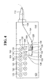
- FIG. 4 is a schematic illustration of a first exemplary embodiment of an auto-splice apparatus, which may be used in practicing the invention, for assisting an operator in splicing the tail end 102 of a first fiber tow 104 to the lead end 106 of a second fiber tow 108.
- the first fiber tow 104 is fed from a first reel 116, containing a coiled portion of the first fiber tow 102, to a fiber placement head 112 of a fiber placement machine 114.
- the second fiber tow 108 is fed from a second reel 118, containing a coiled portion of the second fiber tow 108.
- the first and second reels 116, 118, together with a plurality of other reels 120, are operatively mounted within a creel 122, which is operatively and fixedly attached to the fiber placement machine 114, in the schematic illustration of the first exemplary embodiment of the invention 100, as shown in FIG. 1.
- the creel and the fiber placement machine include a plurality of other tensioning and redirecting devices, illustrated in FIG. 4 by re-direct rollers 124, 126, in the creel 122 and fiber placement head 114, respectively.
- the first exemplary embodiment of the invention 100 also includes a first and second low material sensor 128, 130, operatively disposed and configured for detecting a low material condition of the first and second reels 116, 118, respectively.
- the first exemplary embodiment of the auto-splice apparatus 100 includes a tail end clamping device 132, a tail end trimming device 134, a welding device 136, and a two-position, operator activated, control element, represented by a toggle switch 138 which operatively interconnects the tail and clamping device 132, the tail end trimming device 134, and the welding device 136.
- FIGS. 5-9 are enlarged illustrations of a portion of the elements illustrated in FIG. 4, sequentially showing various steps of a method, according to the invention, for operating the auto-splice apparatus 100.
- FIG. 5 illustrates an operating condition in which the low material sensor 128 has detected a low material condition in the first reel 110, where the coiled portion of the first fiber tow 104, on the reel 116, is nearly exhausted, and the tail end 102 of the first fiber tow 104 is approaching the auto-splice apparatus 100, as the first fiber tow 104 is fed out to the fiber placement head 112.
- the operator of the fiber placement machine 114 stops the feed of the first fiber tow 104 to the fiber placement 114, prior to initiating a first phase of the splicing process.
- the operator moves the toggle switch 138, from the first position as shown in FIG. 5, to the second position, as shown in FIG. 6.
- the auto-splice apparatus 100 performs the first phase of the splicing process, in which the tail end clamping device 138 clamps the tail end 102 of the first tow 104 (which extends through the fiber placement machine 114 and remains attached to the fiber placement head 112) in such a manner that the tail end clamping device 138 retains the tail end 102 within the auto-splice apparatus 100.
- the tail end trimming device 134, of the auto-splice apparatus 100 is then automatically actuated, as part of the first phase of the splicing process, to trim the tail end 102 of the first tow to a desired length, and then retract, to form a trimmed tail end 140 of the first fiber tow 104, to thereby complete the first phase of the splicing process.
- the auto-splice apparatus 100 may be configured to provide a time delay between actuation of the tail end clamping device and actuation of the tail end trimming device, during the first phase of the splicing process.
- the operator inserts the lead end 106 of the second fiber tow 108 into the auto-splice apparatus 100, and the auto-splice apparatus 100 guides the lead end 106 into an overlapped position, adjacent the trimmed tail end 140 of the first fiber tow 104, to form overlapped portions 142, 144 of the first and second fiber tows 104, 108, respectively.
- the auto-splice apparatus 100 will not perform the second phase of the splicing process, and will stay indefinitely at the end of the first phase of the splicing process, until the operator moves the toggle switch 138 from the second position to the first position thereof.
- the auto-splice apparatus 100 therefore provides however much time the operator may need to thread the lead end 106 of the second fiber tow 108 through any redirects 124, or tensioning devices may be present in the creel 122, and inserting the lead end 106 into the auto-splice apparatus 100.
- the second fiber tow 108 is supplied by a second reel 118, which is already present within the creel 122
- the invention may also be practiced by removing the first reel, after the tail end trimming device 134 severs the first fiber tow 104, and mounting a second reel 118, taken from storage outside of the creel, for example, on the drive mechanism upon which the first reel was mounted prior to becoming exhausted.
- the operator moves the toggle switch 138 back to the first position, to initiate a second phase of the splicing process by the auto-splice apparatus 100, in which a welding head 146 of the welding device 136 clamps the overlapping portions 142, 144 of the first and second fiber tows 104, 108 against a support surface 148, of the auto-splice apparatus 100, with a clamping pressure.
- the welding head 146 then applies heat to the overlapped portions 142, 144, for a period of time, to thereby weld the overlapped portions 142, 144 together.
- the auto-splice apparatus 100 moves the welding head 146 away from the support surface 148 to unclamp the welded together overlapped portions 142, 144 of the first and second tows 104, 108, to thereby complete the second phase of the splicing process.
- the welding device 136 may be further configured for cooling the overlapped portions 142, 146 of the first and second fiber tows 104, 108, subsequent to forming the weld, as part of the second phase of the splicing process.
- the first exemplary embodiment of the auto-splice apparatus 100 also includes a welding controller 150, operatively connected for controlling one or more parameters of the welding process, such as the clamping pressure, the heat applied by the welding head, the period of time that the heat is applied, and/or the cooling of the overlapped portions 142, 144 of the first and second fiber tows 104, 108, subsequent to forming the weld.
- a welding controller 150 operatively connected for controlling one or more parameters of the welding process, such as the clamping pressure, the heat applied by the welding head, the period of time that the heat is applied, and/or the cooling of the overlapped portions 142, 144 of the first and second fiber tows 104, 108, subsequent to forming the weld.
- first tows 104 being supplied to a fiber placement head 112
- each of the first fiber tows 104 having associated therewith a separate auto-splice apparatus 100 for assisting an operator in splicing the tail ends of the first fiber tows 104 to the lead ends 106 of one of a plurality of second fiber tows 108 supplied by a plurality of second reels 118, with the splicing process being carried out by the operator with assistance of the auto-splice apparatus 100 according to the illustrations and description given above with reference to FIGS. 4-9.
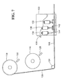
- FIGS. 11 and 12 illustrate a second exemplary embodiment of an auto-splice apparatus 200 for use in an application where a plurality of first reels are operatively mounted in a first creel 202, and a plurality of second reels 118 are mounted in a second creel 204 with the first and second creels 202, 204 being configured for operative alternate attachment to a fiber placement machine 206, in a manner which allows all of the multiple fiber tows being fed to the fiber placement head 208 to be simultaneously and quickly changed by detaching the first creel 202 from the fiber placement machine 206, and operatively attaching the second creel 204 to the fiber placement machine 206, in place of the first creel 202.
- Operation of the fiber placement machine 206 may then be resumed, using second fiber tows from the second creel 204, and replenishment of the first creel 202 may take place off-line, while the fiber placement machine 206 is continuing the fiber placement process using the second tows from the second reels 118 and the second creel 204.
- the process may be reversed by detaching the second creel 204 and reattaching the first creel 202, with the second creel then being replenished off-line.
- a series of creels may be sequentially attached to the fiber placement machine 206, during the fiber placement process, rather than merely alternating a first and a second creel 202, 204.
- creels not only expedites the fiber placement process, by eliminating much of the dead time present in prior fiber placement processes utilizing creels fixedly attached to the fiber placement machine, but also allows the additional flexibility of effectively and efficiently changing the material in one or more of the multiple fiber tows at selected points in the fiber placement process, to allow some of the tows to be changed from one material, such as carbon fiber, to other materials such as fiberglass or Aramid fibers.
- the second exemplary embodiment of the auto-splice apparatus 200 has a first half 210 thereof, fixedly attached to the fiber placement machine 206, for clamping and trimming the tail ends 102, of the first fiber tows 104, and for welding the overlapped portions of the first and second tows 104, 108, following attachments of one of the creels 202, 204 to the fiber placement machine 206.
- the second exemplary embodiment of the auto-splice apparatus 200 has multiple second halves 212 thereof, with one of the multiple second halves 212 being disposed in the first creel 202 and another of the multiple second halves being disposed in the second creel 204.
- the second halves 212 are configured for clamping the respective lead ends of the first and second tows 104, 108 within the first and second creels 202, 204 respectively, when the first and second creels 202, 204 are not operatively connected to the fiber placement machine 206.
- the second halves 212 are further configured for feeding the lead ends of the first and second fiber tows 104, 108, respectively, into the first half 210 of the auto-splice apparatus 200, when the respective first or second creel 202, 204 is operatively attached to the fiber placement machine.
- the first half 210 of the second exemplary embodiment of the auto-splice apparatus 200 includes a tail end clamping device 214, a welding device 216, and a tail end trimming device 218, operatively connected and disposed with respect to one another in a manner very similar to their respective counterparts 132, 136, 134, in the first exemplary embodiment of the auto-splice apparatus 100, described above.
- the tail end clamping device 214 clamps the tail ends of the first tows, extending outward to the fiber placement 208, in place within the fiber placement machine, and the tail end trimming device 218 is actuated to sever the first plys, so that the first creel 202 can be removed, and to simultaneously trim the tail ends of the first plys in a manner facilitating the splicing operation with the auto-splice apparatus 200.
- the lead ends of the second tows 108 are fed into the second half 212 of the auto-splice apparatus attached to the second creel 204. Specifically, the lead ends of the tows are fed beneath one or more feed rollers 220, of the second half 212 of the auto-splice apparatus 200, and are clamped in place by one or more lead end clamps 222 of the second half 212 of the auto-splice apparatus 200.
- alignment features such as alignment pins received in tightly fitting bores, are utilized to accurately align the first and second halves 210, 212 of the auto-splice apparatus 200.
- the second phase of the splicing process is initiated, either by operator activation, or automatically by the auto-splice apparatus in response to signals from one or more sensors which indicates that the creel (202 or 204) is properly attached to the fiber placement machine 206.
- the lead ends of the second fiber tows are fed into the first half 210 of the auto-splice apparatus by the feed rollers 220 in the second half 212 of the auto-splice apparatus 200 attached to the creel (202, 204) attached to the fiber placement machine 206.
- the lead end clamp 222 in the second half 212 of the auto-splice apparatus 200, unclamps the lead ends of the tows, and the feed roller 220 is simultaneously activated for feeding the tows into the first half 210 of the auto-splice apparatus, in an overlapped manner with the tail ends of the first fiber tows, which are then welded together by the welding device 216 of the first half 210 of the auto-splice apparatus 200.
- the invention may be practiced in a wide variety of embodiments other than the second exemplary embodiment described above.
- the auto-splice apparatus 200 may be configured in such a manner that the operator must initiate both a first and a second phase of the splicing process, using a two position control element, in much the same fashion as described above with relation to the first exemplary embodiment 100 of the invention.
- one or both phases of the splicing process may be automatically triggered by control elements within the auto-splice apparatus 200, the fiber placement machine 206, or the creels 202, 204.
- a second half 212 of an auto-splice apparatus 200 may also include additional components, such as a lead end trimming device, for trimming the lead ends to a desired length and configuration.
- one or more of the active components 214, 216, 218, 220, 222 of the first and second halves 210, 212 of the second exemplary embodiment of the auto-splice apparatus 200 may be configured in some embodiments of the invention, as individual multiple components acting on a single one of the multiple tows, or alternatively, configured for simultaneously acting on multiple ones of the multiple fiber tows.
Landscapes
- Engineering & Computer Science (AREA)
- Mechanical Engineering (AREA)
- Robotics (AREA)
- Chemical & Material Sciences (AREA)
- Composite Materials (AREA)
- Treatment Of Fiber Materials (AREA)
- Moulding By Coating Moulds (AREA)
- Replacing, Conveying, And Pick-Finding For Filamentary Materials (AREA)
Applications Claiming Priority (1)
| Application Number | Priority Date | Filing Date | Title |
|---|---|---|---|
| US71129105P | 2005-08-25 | 2005-08-25 |
Publications (3)
| Publication Number | Publication Date |
|---|---|
| EP1757434A2 true EP1757434A2 (fr) | 2007-02-28 |
| EP1757434A3 EP1757434A3 (fr) | 2009-09-16 |
| EP1757434B1 EP1757434B1 (fr) | 2014-12-17 |
Family
ID=37540653
Family Applications (1)
| Application Number | Title | Priority Date | Filing Date |
|---|---|---|---|
| EP06119545.9A Not-in-force EP1757434B1 (fr) | 2005-08-25 | 2006-08-25 | Cantre remplaçable dans une machine pour l'application de fibes |
Country Status (4)
| Country | Link |
|---|---|
| US (1) | US7632372B2 (fr) |
| EP (1) | EP1757434B1 (fr) |
| CA (1) | CA2557088A1 (fr) |
| ES (1) | ES2531072T3 (fr) |
Cited By (5)
| Publication number | Priority date | Publication date | Assignee | Title |
|---|---|---|---|---|
| EP2492088A1 (fr) * | 2011-02-25 | 2012-08-29 | Mag Ias, Llc | Dispositif et procédé pour charger automatiquement des bobines a positionnement de fibres |
| WO2014072120A1 (fr) * | 2012-11-08 | 2014-05-15 | Wobben Properties Gmbh | Dispositif et procédé de fabrication de demi-produits pour pales de rotor d'éolienne, et pale de rotor et éolienne pourvues de ces demi-produits |
| DE102013223851A1 (de) * | 2013-11-21 | 2015-05-21 | Airbus Operations Gmbh | Legevorrichtung und Verfahren zum Ablegen von Faserbändern |
| EP4023421A1 (fr) * | 2021-01-04 | 2022-07-06 | The Boeing Company | Formation de contours dans un système de placement de fibres |
| DE102023113507A1 (de) * | 2023-05-23 | 2024-11-28 | Deutsches Zentrum für Luft- und Raumfahrt e.V. | Konsolidierungseinrichtung und Vorrichtung zum kontinuierlichen Ultraschallschweißen |
Families Citing this family (18)
| Publication number | Priority date | Publication date | Assignee | Title |
|---|---|---|---|---|
| KR20090122951A (ko) * | 2007-03-30 | 2009-12-01 | 파나소닉 주식회사 | 작업 장치, 점착 테이프 첩부 장치 및 테이프 부재의 추가 방법 |
| US9027623B2 (en) * | 2009-09-22 | 2015-05-12 | Flexible Steel Lacing Company | Welding apparatus for conveyor belts and method |
| FR2972672B1 (fr) | 2011-03-18 | 2013-03-15 | Coriolis Composites Attn Olivier Bouroullec | Machine d'application de fibres avec systeme de securite |
| DE102011007020A1 (de) * | 2011-04-08 | 2012-10-11 | Voith Patent Gmbh | Vorrichtung und Verfahren zur Herstellung von Faserformlingen, die insbesondere eine Vorstufe bei der Herstellung von faserverstärkten Kunststoff-Bauteilen darstellen |
| ES2681370T3 (es) | 2012-12-28 | 2018-09-12 | Flexible Steel Lacing Company | Aparato y método de soldadura para cintas transportadoras |
| EP2808158A1 (fr) * | 2013-05-31 | 2014-12-03 | Siemens Aktiengesellschaft | Procédé et dispositif de pose d'une matière fibreuse sur une surface de moule |
| US9428298B2 (en) | 2013-11-05 | 2016-08-30 | Sonoco Development, Inc. | Dividerless palletized packaging system with interlocking tray and corner posts |
| US9782938B2 (en) * | 2014-03-21 | 2017-10-10 | The Boeing Company | Manufacturing system for composite structures |
| JP6954018B2 (ja) * | 2017-11-09 | 2021-10-27 | トヨタ自動車株式会社 | 樹脂が含浸した第1の繊維と第2の繊維とを接合する装置および方法 |
| CN108100640A (zh) * | 2018-01-04 | 2018-06-01 | 泰山玻璃纤维有限公司 | 基于视觉精确定位的短切纤维自动上纱系统 |
| CN108544770B (zh) * | 2018-06-06 | 2023-09-19 | 淮北宇鑫新型材料有限公司 | 一种纤维筋材生产设备及生产方法 |
| CN108861802B (zh) * | 2018-06-11 | 2020-06-30 | 浙江大学 | 一种集成在自动铺放设备的铺丝头上的纱架结构 |
| DE102019112554B4 (de) * | 2019-05-14 | 2020-12-17 | Cetex Institut gGmbH | Verfahren und Vorrichtung zum kontinuierlichen Prozessieren mehrerer Rovings |
| CN111300803A (zh) * | 2020-03-27 | 2020-06-19 | 四川德源石油天然气工程有限公司 | 一种管道、缠绕耐磨保护层安装装置及安装方法 |
| CN112060631B (zh) * | 2020-09-17 | 2025-06-06 | 山东中恒景新碳纤维科技发展有限公司 | 一种自动铺丝中采用换枪盘的纱架快速更换装置 |
| CN114770922B (zh) * | 2022-05-19 | 2024-07-16 | 安徽绿动能源有限公司 | 全自动换位式多纤维缠绕一体机 |
| CN114986941B (zh) * | 2022-06-29 | 2023-03-21 | 南京航空航天大学 | 一种干纤维自动铺丝机快拆式盘状纱弹夹机构 |
| CN121179766B (zh) * | 2025-11-26 | 2026-02-27 | 太原理工大学 | 一种环向分布多窄带同时铺放装备及方法 |
Citations (1)
| Publication number | Priority date | Publication date | Assignee | Title |
|---|---|---|---|---|
| US3957410A (en) | 1972-04-14 | 1976-05-18 | Goldsworthy Engineering, Inc. | Means for centrifugally casting a plastic tubular member |
Family Cites Families (11)
| Publication number | Priority date | Publication date | Assignee | Title |
|---|---|---|---|---|
| US3055786A (en) * | 1960-07-19 | 1962-09-25 | Du Pont | Filament handling process and apparatus |
| US3525207A (en) * | 1968-10-14 | 1970-08-25 | Techniservice Corp | Splicing of textile strands |
| US3695975A (en) * | 1970-10-16 | 1972-10-03 | Willie Vincent Williams | Apparatus for rapidly splicing a multitude of thermoplastic yarn ends |
| US4428992A (en) * | 1981-11-21 | 1984-01-31 | Hitco | Method of splicing reinforcement fiber |
| US4515328A (en) * | 1983-11-17 | 1985-05-07 | Burlington Industries, Inc. | Incremental modular creel system |
| US5266139A (en) * | 1992-10-02 | 1993-11-30 | General Dynamics Corporation, Space Systems Division | Continuous processing/in-situ curing of incrementally applied resin matrix composite materials |
| IT1274513B (it) * | 1995-05-16 | 1997-07-17 | Salmoiraghi Srl | Dispositivo per trasportare bobine cariche di filo in corrispondenza di una macchina tessile e per asportare bobine scariche da quest'ultima |
| ES2212878B1 (es) | 2002-03-05 | 2005-07-16 | Manuel Torres Martinez | Cabezal multiaplicador de tiras de fibra. |
| US7093638B2 (en) * | 2003-04-21 | 2006-08-22 | Lignum Vitae Limited | Apparatus and method for manufacture and use of composite fiber components |
| ES2529448T3 (es) * | 2004-04-21 | 2015-02-20 | Ingersoll Machine Tools, Inc. | Colocación automatizada de fibras que usa múltiples cabezales de colocación, estizolas sustituibles y cabezales de colocación sustituibles |
| US7472736B2 (en) * | 2005-02-14 | 2009-01-06 | The Boeing Company | Modular head lamination device and method |
-
2006
- 2006-08-25 US US11/510,164 patent/US7632372B2/en active Active
- 2006-08-25 CA CA002557088A patent/CA2557088A1/fr not_active Abandoned
- 2006-08-25 EP EP06119545.9A patent/EP1757434B1/fr not_active Not-in-force
- 2006-08-25 ES ES06119545T patent/ES2531072T3/es active Active
Patent Citations (1)
| Publication number | Priority date | Publication date | Assignee | Title |
|---|---|---|---|---|
| US3957410A (en) | 1972-04-14 | 1976-05-18 | Goldsworthy Engineering, Inc. | Means for centrifugally casting a plastic tubular member |
Cited By (8)
| Publication number | Priority date | Publication date | Assignee | Title |
|---|---|---|---|---|
| EP2492088A1 (fr) * | 2011-02-25 | 2012-08-29 | Mag Ias, Llc | Dispositif et procédé pour charger automatiquement des bobines a positionnement de fibres |
| US8931725B2 (en) | 2011-02-25 | 2015-01-13 | Fives Machining Systems, Inc. | Fiber placement auto spool loader |
| WO2014072120A1 (fr) * | 2012-11-08 | 2014-05-15 | Wobben Properties Gmbh | Dispositif et procédé de fabrication de demi-produits pour pales de rotor d'éolienne, et pale de rotor et éolienne pourvues de ces demi-produits |
| AU2013343836B2 (en) * | 2012-11-08 | 2016-07-21 | Wobben Properties Gmbh | Device and method for producing semifinished products for wind power system rotor blades and rotor blade and wind energy system produced therewith |
| DE102013223851A1 (de) * | 2013-11-21 | 2015-05-21 | Airbus Operations Gmbh | Legevorrichtung und Verfahren zum Ablegen von Faserbändern |
| EP4023421A1 (fr) * | 2021-01-04 | 2022-07-06 | The Boeing Company | Formation de contours dans un système de placement de fibres |
| US11565483B2 (en) | 2021-01-04 | 2023-01-31 | The Boeing Company | Contour forming in fiber-placement system |
| DE102023113507A1 (de) * | 2023-05-23 | 2024-11-28 | Deutsches Zentrum für Luft- und Raumfahrt e.V. | Konsolidierungseinrichtung und Vorrichtung zum kontinuierlichen Ultraschallschweißen |
Also Published As
| Publication number | Publication date |
|---|---|
| EP1757434B1 (fr) | 2014-12-17 |
| EP1757434A3 (fr) | 2009-09-16 |
| US7632372B2 (en) | 2009-12-15 |
| ES2531072T3 (es) | 2015-03-10 |
| CA2557088A1 (fr) | 2007-02-25 |
| US20070044897A1 (en) | 2007-03-01 |
Similar Documents
| Publication | Publication Date | Title |
|---|---|---|
| EP1757552B1 (fr) | Episseur automatique et procédé d'épissage automatique pour une machine de placement de fibres | |
| US7632372B2 (en) | Replaceable creel in a fiber placement machine | |
| KR102344422B1 (ko) | 선재 권취 장치 및 선재 권취 방법 | |
| CN105128172A (zh) | 用于制造纤维预成形件的设备与方法 | |
| KR20140050085A (ko) | 첨단 복합 라미네이트를 제조하기 위한 시스템 및 방법 | |
| EP1008543A1 (fr) | Dispositif et méthode pour former un raccordement sur une bande de papier | |
| CN108328388B (zh) | 一种生产胶袋的薄膜自动换料机 | |
| KR20200046082A (ko) | 열가소성 복합 마스터 쉬트와 테이프 및 그 제조 방법 | |
| US7621479B2 (en) | Supply-roll switching apparatus | |
| CN110914928B (zh) | 电线熔敷装置 | |
| EP0581493B1 (fr) | Méthode de appareil pour le transfert automatique du fil sur une machine d'usinage par électroérosion | |
| CN111511667B (zh) | 片体供给装置以及片体供给方法 | |
| JP4512474B2 (ja) | フィルム接合装置 | |
| EP1911572B1 (fr) | Appareil et procédé pour la jonction de feuilles de caoutchouc | |
| EP2928801B1 (fr) | Procédé et système pour alimenter en matériau une machine de pose | |
| US20030110606A1 (en) | Method and device for winding and attaching warp strips onto the drum of a cone sectional warping machine | |
| US11780182B2 (en) | Lamination head having self-threading capability | |
| JP2008307792A (ja) | フィラメントワインディング装置 | |
| CN117620531A (zh) | 叠焊机及其控制方法 | |
| JP2000237921A (ja) | ワイヤ―カット式の放電加工機、及び、これに用いるワイヤ―供給装置 | |
| JP2002025600A (ja) | 電極供給装置及び電極供給方法 | |
| EP3912942B1 (fr) | Système et procédé pour aligner et joindre les mêmes côtés de deux matériaux en bande | |
| CN118198194A (zh) | 焊带换料系统及方法和焊接设备 | |
| CN111491879B (zh) | 片体供给装置以及片体供给方法 | |
| JP2008290399A (ja) | 補強布供給装置 |
Legal Events
| Date | Code | Title | Description |
|---|---|---|---|
| PUAI | Public reference made under article 153(3) epc to a published international application that has entered the european phase |
Free format text: ORIGINAL CODE: 0009012 |
|
| AK | Designated contracting states |
Kind code of ref document: A2 Designated state(s): AT BE BG CH CY CZ DE DK EE ES FI FR GB GR HU IE IS IT LI LT LU LV MC NL PL PT RO SE SI SK TR |
|
| AX | Request for extension of the european patent |
Extension state: AL BA HR MK YU |
|
| PUAL | Search report despatched |
Free format text: ORIGINAL CODE: 0009013 |
|
| AK | Designated contracting states |
Kind code of ref document: A3 Designated state(s): AT BE BG CH CY CZ DE DK EE ES FI FR GB GR HU IE IS IT LI LT LU LV MC NL PL PT RO SE SI SK TR |
|
| AX | Request for extension of the european patent |
Extension state: AL BA HR MK RS |
|
| 17P | Request for examination filed |
Effective date: 20100127 |
|
| AKX | Designation fees paid |
Designated state(s): AT BE BG CH CY CZ DE DK EE ES FI FR GB GR HU IE IS IT LI LT LU LV MC NL PL PT RO SE SI SK TR |
|
| 17Q | First examination report despatched |
Effective date: 20100526 |
|
| REG | Reference to a national code |
Ref country code: DE Ref legal event code: R079 Ref document number: 602006043999 Country of ref document: DE Free format text: PREVIOUS MAIN CLASS: B29C0070380000 Ipc: B29C0053800000 |
|
| RIC1 | Information provided on ipc code assigned before grant |
Ipc: B29C 70/38 20060101ALI20140502BHEP Ipc: B29C 53/80 20060101AFI20140502BHEP Ipc: B65H 49/32 20060101ALI20140502BHEP Ipc: B29C 53/82 20060101ALI20140502BHEP Ipc: B65H 67/02 20060101ALI20140502BHEP |
|
| GRAP | Despatch of communication of intention to grant a patent |
Free format text: ORIGINAL CODE: EPIDOSNIGR1 |
|
| INTG | Intention to grant announced |
Effective date: 20140721 |
|
| GRAS | Grant fee paid |
Free format text: ORIGINAL CODE: EPIDOSNIGR3 |
|
| GRAA | (expected) grant |
Free format text: ORIGINAL CODE: 0009210 |
|
| AK | Designated contracting states |
Kind code of ref document: B1 Designated state(s): AT BE BG CH CY CZ DE DK EE ES FI FR GB GR HU IE IS IT LI LT LU LV MC NL PL PT RO SE SI SK TR |
|
| REG | Reference to a national code |
Ref country code: GB Ref legal event code: FG4D |
|
| REG | Reference to a national code |
Ref country code: CH Ref legal event code: EP |
|
| REG | Reference to a national code |
Ref country code: IE Ref legal event code: FG4D |
|
| REG | Reference to a national code |
Ref country code: AT Ref legal event code: REF Ref document number: 701555 Country of ref document: AT Kind code of ref document: T Effective date: 20150115 |
|
| REG | Reference to a national code |
Ref country code: DE Ref legal event code: R096 Ref document number: 602006043999 Country of ref document: DE Effective date: 20150212 |
|
| REG | Reference to a national code |
Ref country code: ES Ref legal event code: FG2A Ref document number: 2531072 Country of ref document: ES Kind code of ref document: T3 Effective date: 20150310 |
|
| PG25 | Lapsed in a contracting state [announced via postgrant information from national office to epo] |
Ref country code: LT Free format text: LAPSE BECAUSE OF FAILURE TO SUBMIT A TRANSLATION OF THE DESCRIPTION OR TO PAY THE FEE WITHIN THE PRESCRIBED TIME-LIMIT Effective date: 20141217 Ref country code: FI Free format text: LAPSE BECAUSE OF FAILURE TO SUBMIT A TRANSLATION OF THE DESCRIPTION OR TO PAY THE FEE WITHIN THE PRESCRIBED TIME-LIMIT Effective date: 20141217 |
|
| REG | Reference to a national code |
Ref country code: LT Ref legal event code: MG4D |
|
| PG25 | Lapsed in a contracting state [announced via postgrant information from national office to epo] |
Ref country code: GR Free format text: LAPSE BECAUSE OF FAILURE TO SUBMIT A TRANSLATION OF THE DESCRIPTION OR TO PAY THE FEE WITHIN THE PRESCRIBED TIME-LIMIT Effective date: 20150318 Ref country code: SE Free format text: LAPSE BECAUSE OF FAILURE TO SUBMIT A TRANSLATION OF THE DESCRIPTION OR TO PAY THE FEE WITHIN THE PRESCRIBED TIME-LIMIT Effective date: 20141217 Ref country code: LV Free format text: LAPSE BECAUSE OF FAILURE TO SUBMIT A TRANSLATION OF THE DESCRIPTION OR TO PAY THE FEE WITHIN THE PRESCRIBED TIME-LIMIT Effective date: 20141217 |
|
| REG | Reference to a national code |
Ref country code: AT Ref legal event code: MK05 Ref document number: 701555 Country of ref document: AT Kind code of ref document: T Effective date: 20141217 |
|
| PG25 | Lapsed in a contracting state [announced via postgrant information from national office to epo] |
Ref country code: NL Free format text: LAPSE BECAUSE OF FAILURE TO SUBMIT A TRANSLATION OF THE DESCRIPTION OR TO PAY THE FEE WITHIN THE PRESCRIBED TIME-LIMIT Effective date: 20141217 |
|
| REG | Reference to a national code |
Ref country code: DE Ref legal event code: R082 Ref document number: 602006043999 Country of ref document: DE Representative=s name: HOEGER, STELLRECHT & PARTNER PATENTANWAELTE MB, DE |
|
| PG25 | Lapsed in a contracting state [announced via postgrant information from national office to epo] |
Ref country code: RO Free format text: LAPSE BECAUSE OF FAILURE TO SUBMIT A TRANSLATION OF THE DESCRIPTION OR TO PAY THE FEE WITHIN THE PRESCRIBED TIME-LIMIT Effective date: 20141217 Ref country code: EE Free format text: LAPSE BECAUSE OF FAILURE TO SUBMIT A TRANSLATION OF THE DESCRIPTION OR TO PAY THE FEE WITHIN THE PRESCRIBED TIME-LIMIT Effective date: 20141217 Ref country code: SK Free format text: LAPSE BECAUSE OF FAILURE TO SUBMIT A TRANSLATION OF THE DESCRIPTION OR TO PAY THE FEE WITHIN THE PRESCRIBED TIME-LIMIT Effective date: 20141217 Ref country code: CZ Free format text: LAPSE BECAUSE OF FAILURE TO SUBMIT A TRANSLATION OF THE DESCRIPTION OR TO PAY THE FEE WITHIN THE PRESCRIBED TIME-LIMIT Effective date: 20141217 |
|
| PG25 | Lapsed in a contracting state [announced via postgrant information from national office to epo] |
Ref country code: PL Free format text: LAPSE BECAUSE OF FAILURE TO SUBMIT A TRANSLATION OF THE DESCRIPTION OR TO PAY THE FEE WITHIN THE PRESCRIBED TIME-LIMIT Effective date: 20141217 Ref country code: AT Free format text: LAPSE BECAUSE OF FAILURE TO SUBMIT A TRANSLATION OF THE DESCRIPTION OR TO PAY THE FEE WITHIN THE PRESCRIBED TIME-LIMIT Effective date: 20141217 Ref country code: IS Free format text: LAPSE BECAUSE OF FAILURE TO SUBMIT A TRANSLATION OF THE DESCRIPTION OR TO PAY THE FEE WITHIN THE PRESCRIBED TIME-LIMIT Effective date: 20150417 |
|
| REG | Reference to a national code |
Ref country code: DE Ref legal event code: R097 Ref document number: 602006043999 Country of ref document: DE |
|
| PLBE | No opposition filed within time limit |
Free format text: ORIGINAL CODE: 0009261 |
|
| STAA | Information on the status of an ep patent application or granted ep patent |
Free format text: STATUS: NO OPPOSITION FILED WITHIN TIME LIMIT |
|
| PG25 | Lapsed in a contracting state [announced via postgrant information from national office to epo] |
Ref country code: DK Free format text: LAPSE BECAUSE OF FAILURE TO SUBMIT A TRANSLATION OF THE DESCRIPTION OR TO PAY THE FEE WITHIN THE PRESCRIBED TIME-LIMIT Effective date: 20141217 |
|
| 26N | No opposition filed |
Effective date: 20150918 |
|
| PG25 | Lapsed in a contracting state [announced via postgrant information from national office to epo] |
Ref country code: SI Free format text: LAPSE BECAUSE OF FAILURE TO SUBMIT A TRANSLATION OF THE DESCRIPTION OR TO PAY THE FEE WITHIN THE PRESCRIBED TIME-LIMIT Effective date: 20141217 |
|
| REG | Reference to a national code |
Ref country code: DE Ref legal event code: R119 Ref document number: 602006043999 Country of ref document: DE |
|
| PG25 | Lapsed in a contracting state [announced via postgrant information from national office to epo] |
Ref country code: LU Free format text: LAPSE BECAUSE OF FAILURE TO SUBMIT A TRANSLATION OF THE DESCRIPTION OR TO PAY THE FEE WITHIN THE PRESCRIBED TIME-LIMIT Effective date: 20150825 Ref country code: MC Free format text: LAPSE BECAUSE OF FAILURE TO SUBMIT A TRANSLATION OF THE DESCRIPTION OR TO PAY THE FEE WITHIN THE PRESCRIBED TIME-LIMIT Effective date: 20141217 |
|
| REG | Reference to a national code |
Ref country code: CH Ref legal event code: PL |
|
| GBPC | Gb: european patent ceased through non-payment of renewal fee |
Effective date: 20150825 |
|
| PG25 | Lapsed in a contracting state [announced via postgrant information from national office to epo] |
Ref country code: CH Free format text: LAPSE BECAUSE OF NON-PAYMENT OF DUE FEES Effective date: 20150831 Ref country code: LI Free format text: LAPSE BECAUSE OF NON-PAYMENT OF DUE FEES Effective date: 20150831 |
|
| PG25 | Lapsed in a contracting state [announced via postgrant information from national office to epo] |
Ref country code: BE Free format text: LAPSE BECAUSE OF FAILURE TO SUBMIT A TRANSLATION OF THE DESCRIPTION OR TO PAY THE FEE WITHIN THE PRESCRIBED TIME-LIMIT Effective date: 20141217 |
|
| REG | Reference to a national code |
Ref country code: IE Ref legal event code: MM4A |
|
| REG | Reference to a national code |
Ref country code: FR Ref legal event code: ST Effective date: 20160429 |
|
| PG25 | Lapsed in a contracting state [announced via postgrant information from national office to epo] |
Ref country code: DE Free format text: LAPSE BECAUSE OF NON-PAYMENT OF DUE FEES Effective date: 20160301 Ref country code: IE Free format text: LAPSE BECAUSE OF NON-PAYMENT OF DUE FEES Effective date: 20150825 Ref country code: GB Free format text: LAPSE BECAUSE OF NON-PAYMENT OF DUE FEES Effective date: 20150825 |
|
| PG25 | Lapsed in a contracting state [announced via postgrant information from national office to epo] |
Ref country code: FR Free format text: LAPSE BECAUSE OF NON-PAYMENT OF DUE FEES Effective date: 20150831 |
|
| PG25 | Lapsed in a contracting state [announced via postgrant information from national office to epo] |
Ref country code: IT Free format text: LAPSE BECAUSE OF NON-PAYMENT OF DUE FEES Effective date: 20150825 |
|
| PG25 | Lapsed in a contracting state [announced via postgrant information from national office to epo] |
Ref country code: HU Free format text: LAPSE BECAUSE OF FAILURE TO SUBMIT A TRANSLATION OF THE DESCRIPTION OR TO PAY THE FEE WITHIN THE PRESCRIBED TIME-LIMIT; INVALID AB INITIO Effective date: 20060825 Ref country code: BG Free format text: LAPSE BECAUSE OF FAILURE TO SUBMIT A TRANSLATION OF THE DESCRIPTION OR TO PAY THE FEE WITHIN THE PRESCRIBED TIME-LIMIT Effective date: 20141217 |
|
| PG25 | Lapsed in a contracting state [announced via postgrant information from national office to epo] |
Ref country code: ES Free format text: LAPSE BECAUSE OF NON-PAYMENT OF DUE FEES Effective date: 20150826 Ref country code: CY Free format text: LAPSE BECAUSE OF FAILURE TO SUBMIT A TRANSLATION OF THE DESCRIPTION OR TO PAY THE FEE WITHIN THE PRESCRIBED TIME-LIMIT Effective date: 20141217 |
|
| PG25 | Lapsed in a contracting state [announced via postgrant information from national office to epo] |
Ref country code: TR Free format text: LAPSE BECAUSE OF FAILURE TO SUBMIT A TRANSLATION OF THE DESCRIPTION OR TO PAY THE FEE WITHIN THE PRESCRIBED TIME-LIMIT Effective date: 20141217 |
|
| REG | Reference to a national code |
Ref country code: ES Ref legal event code: FD2A Effective date: 20180706 |
|
| PG25 | Lapsed in a contracting state [announced via postgrant information from national office to epo] |
Ref country code: PT Free format text: LAPSE BECAUSE OF FAILURE TO SUBMIT A TRANSLATION OF THE DESCRIPTION OR TO PAY THE FEE WITHIN THE PRESCRIBED TIME-LIMIT Effective date: 20141217 |