EP1757546A2 - Bobineuse à rouleaux porteurs - Google Patents
Bobineuse à rouleaux porteurs Download PDFInfo
- Publication number
- EP1757546A2 EP1757546A2 EP06115623A EP06115623A EP1757546A2 EP 1757546 A2 EP1757546 A2 EP 1757546A2 EP 06115623 A EP06115623 A EP 06115623A EP 06115623 A EP06115623 A EP 06115623A EP 1757546 A2 EP1757546 A2 EP 1757546A2
- Authority
- EP
- European Patent Office
- Prior art keywords
- winding
- roll
- roller
- winding machine
- loading
- Prior art date
- Legal status (The legal status is an assumption and is not a legal conclusion. Google has not performed a legal analysis and makes no representation as to the accuracy of the status listed.)
- Granted
Links
- 238000004804 winding Methods 0.000 title claims abstract description 164
- 238000000034 method Methods 0.000 claims description 19
- 239000000463 material Substances 0.000 claims description 6
- 238000013016 damping Methods 0.000 claims description 4
- 230000000087 stabilizing effect Effects 0.000 description 3
- 230000000712 assembly Effects 0.000 description 1
- 238000000429 assembly Methods 0.000 description 1
- 238000003490 calendering Methods 0.000 description 1
- 238000010276 construction Methods 0.000 description 1
- 239000012050 conventional carrier Substances 0.000 description 1
- 230000008092 positive effect Effects 0.000 description 1
- 230000006641 stabilisation Effects 0.000 description 1
- 238000011105 stabilization Methods 0.000 description 1
Images

Classifications
-
- B—PERFORMING OPERATIONS; TRANSPORTING
- B65—CONVEYING; PACKING; STORING; HANDLING THIN OR FILAMENTARY MATERIAL
- B65H—HANDLING THIN OR FILAMENTARY MATERIAL, e.g. SHEETS, WEBS, CABLES
- B65H18/00—Winding webs
- B65H18/08—Web-winding mechanisms
- B65H18/14—Mechanisms in which power is applied to web roll, e.g. to effect continuous advancement of web
- B65H18/20—Mechanisms in which power is applied to web roll, e.g. to effect continuous advancement of web the web roll being supported on two parallel rollers at least one of which is driven
-
- B—PERFORMING OPERATIONS; TRANSPORTING
- B65—CONVEYING; PACKING; STORING; HANDLING THIN OR FILAMENTARY MATERIAL
- B65H—HANDLING THIN OR FILAMENTARY MATERIAL, e.g. SHEETS, WEBS, CABLES
- B65H18/00—Winding webs
- B65H18/02—Supporting web roll
- B65H18/023—Supporting web roll on its outer circumference
- B65H18/025—Parallel rollers type
-
- B—PERFORMING OPERATIONS; TRANSPORTING
- B65—CONVEYING; PACKING; STORING; HANDLING THIN OR FILAMENTARY MATERIAL
- B65H—HANDLING THIN OR FILAMENTARY MATERIAL, e.g. SHEETS, WEBS, CABLES
- B65H18/00—Winding webs
- B65H18/08—Web-winding mechanisms
- B65H18/26—Mechanisms for controlling contact pressure on winding-web package, e.g. for regulating the quantity of air between web layers
-
- B—PERFORMING OPERATIONS; TRANSPORTING
- B65—CONVEYING; PACKING; STORING; HANDLING THIN OR FILAMENTARY MATERIAL
- B65H—HANDLING THIN OR FILAMENTARY MATERIAL, e.g. SHEETS, WEBS, CABLES
- B65H2301/00—Handling processes for sheets or webs
- B65H2301/40—Type of handling process
- B65H2301/41—Winding, unwinding
- B65H2301/414—Winding
- B65H2301/4148—Winding slitting
-
- B—PERFORMING OPERATIONS; TRANSPORTING
- B65—CONVEYING; PACKING; STORING; HANDLING THIN OR FILAMENTARY MATERIAL
- B65H—HANDLING THIN OR FILAMENTARY MATERIAL, e.g. SHEETS, WEBS, CABLES
- B65H2515/00—Physical entities not provided for in groups B65H2511/00 or B65H2513/00
- B65H2515/50—Vibrations; Oscillations
-
- B—PERFORMING OPERATIONS; TRANSPORTING
- B65—CONVEYING; PACKING; STORING; HANDLING THIN OR FILAMENTARY MATERIAL
- B65H—HANDLING THIN OR FILAMENTARY MATERIAL, e.g. SHEETS, WEBS, CABLES
- B65H2601/00—Problem to be solved or advantage achieved
- B65H2601/10—Ensuring correct operation
- B65H2601/12—Compensating; Taking-up
- B65H2601/125—Vibration
Definitions
- the invention relates to a carrier roll winding machine for winding a material web, in particular a paper or board web, on at least one winding tube to at least one winding roll, which is located in a winding bed formed by two support rollers, with the at least one winding roller in the winding bed pressing load roller.
- Material webs must be wound up into shipping or finishing rolls before they can be shipped.
- reel cores usually winding cores are used, which are preferably made of cardboard.
- the finished rolls are produced in that so-called mother or spool rolls, which are produced at the exit of a paper machine or after the calendering, unwound, cut in the longitudinal direction and then wound on each winding cores.
- mother or spool rolls which are produced at the exit of a paper machine or after the calendering, unwound, cut in the longitudinal direction and then wound on each winding cores.
- These cores lie in a winding bed formed by two support rollers of a double carrier roll winding machine.
- a double carrier roll winding machine as for example from the DE 200 13 319 U1 or the EP 0 792 245 B1 is known, according to the number of individual webs produced from the original material web by longitudinal cuts several cores next to each other in the winding bed, even if subsequently for reasons of simplicity always only a single winding tube is addressed in conjunction with a wound on her web.
- a carrier roll winding machine is known in the the winding roll is pressed into the winding bed by a loading roller arranged vertically above the winding roll.
- the load roller exerts a minimum load of 0.5 kN / m on the reel during the entire winding process.
- the loading roller serves to achieve a desired winding hardness during winding.
- the winding roll should namely be wound harder inside than in the area of the circumference.
- the load roller presses the winding roller with a predetermined force in the winding bed into it. As a result, this can wrap relatively hard, that is, the winding hardness is high enough in the region of the roll core or the winding tube. As the weight increases with increasing roll diameter, the load is returned by the load roll.
- the invention is therefore based on the object to provide an improved carrier roll winding machine, which allows the generation of wound rolls with improved winding qualities.
- This object is achieved in a carrier roll winding machine of the type mentioned above in that the loading roller is connected via a frame with a support rollers winding machine supporting base plate.
- At least one further loading roller is connected via a preferably common frame to a base plate carrying the carrier roll winding machine.
- the loading rollers are preferably arranged such that the loading roller is pressable on one side to a passing through the axis of rotation of the at least one winding roll perpendicular to the at least one winding roll and that the at least one further loading roller mutually to the passing through the axis of rotation of the at least one winding roll perpendicular to the at least one winding roll is pressed. In this way, the stabilizing and preferably equally large forces are introduced into the system on both sides.
- the loading roller is mutually arranged to the incoming support roller with respect to the passing through the axis of rotation of the at least one winding roll perpendicular and if the at least one further loading roller equilateral to the incoming support roller with respect to the through the axis of rotation of the at least one winding roll going vertical is arranged. This winding roll is stabilized.
- the preferably common frame each comprises a rocker for the respective loading roller and that the respective loading roller respectively is rotatably mounted at the outer end of the associated rocker.
- the respective loading roller is mounted on the frame, in particular on the rocker, in such a way that it preferably presses against the winding roller at least laterally.
- the first load roller initially also presses vertically from above against the winding roll. Only a lateral arrangement of the loading roller with respect to the winding roll can dampen the rocking or vibration of the roll.
- the loading roller can be fastened either on a rocker swingable about an axis of rotation or on a linear guide; the function of the loading roller is independent of whether it is guided on a straight line or a circular path.
- the respective loading roller is inclined with respect to a passing through the axis of rotation of the winding roll, the connecting line between the two support rollers intersecting at right angles intersecting bisectors, at least during most of the winding process, that is at least from reaching a predetermined winding diameter.
- the axis of rotation of the rocker of the loading roller at least during the winding process at least for most of the time laterally below the axis of rotation of the at least one winding roll and if the axis of rotation of the rocker of at least one further loading roller at least during the winding process laterally above the axis of rotation at least one winding roll is located. This provides excellent conditions for the best possible stabilization of the winding roll.
- the respective rocker extends over the entire width of the at least one winding roller or it comprises two laterally guided on the at least one winding roller pivoting arms.
- the respective rocker is pressed against the winding roll at least by means of a preferably controllable / adjustable pressure system.
- the respective preferably controllable / controllable the pressing system preferably comprises at least one hydraulic or pneumatic cylinder, in particular two hydraulic or pneumatic cylinders arranged laterally of the at least one winding roller, or an electric spindle.
- Such components are characterized in particular by a good functionality.
- the hydraulic cylinder, the pneumatic cylinder or the electric spindle is preferably articulated on the rocker at the free end of the rocker, in particular in the vicinity of the loading roller.
- the respective rocker is arranged movable relative to a base plate on which at least one of the support rollers is also rotatably mounted.
- the loading roller comprises a damping device arranged or connected in its interior, in its rocker or with its pressure system.
- the loading roller comprises a damping device arranged in the interior of the loading roller or on the guide, that is to say on the drive, of the loading roller.
- FIG. 1 shows a carrier roll winding machine 1 for winding a material web 2, in particular a paper or board web, on at least one winding tube 3 to at least one winding roller 4 during the winding process.
- the winding roll 4 lies in one of two support rollers 5, 6 formed winding bed 7 and it is pressed by at least one load roller 8 in the winding bed 7.
- the material web 2 is cut by a non-illustrated, known in the art slitting device before winding into several individual webs, then laterally, as shown, to the shell 9 of the support roller 5 or alternatively through the gap G between the support rollers 5, 6 in around the winding bed 7 are guided, where they are wound on aligned winding cores 3.
- bobbins 4 is now connected via a frame 10 with a support rollers winding machine 1 supporting base plate 11 associated load roller 8 which extends over the entire width of all adjacent bobbins 4 and presses the bobbins 4 in the winding bed 7.
- a further loading roller 12 is disposed above the winding rollers 4, which is also connected via the common frame 10 with the support rollers winding machine 1 supporting base plate 11. This further loading roller 12 extends over the entire width of all adjacent winding rollers 4 and presses the winding rollers 4 in the winding bed.
- the two loading rollers 8, 12 are generally arranged such that the loading roller 8 can be pressed on one side to a passing through the rotation axis 13 of the winding rollers 4 vertical S against the winding rollers 4 and that the another load roller 12 mutually to the passing through the rotation axis 13 of the winding rollers 4 vertical S against the winding roller 4 can be pressed.
- the loading roller 8 is mutually arranged to the incoming support roller 4 with respect to the going through the rotation axis 13 of the winding rollers 4 vertical S and the further load roller 12 is equal to the incoming support roller 4 with respect to the through the axis of rotation 13 of the winding rolls 4 going vertical S arranged.
- the frame 10 each comprises a rocker 14, 15 for the respective loading roller 8, 12, which in turn is rotatably mounted respectively at the outer end of the associated rocker 14, 15.
- the rockers 14, 15 are in turn pivotally mounted about a respective axis of rotation 16, 17, which are mounted in an upwardly projecting lug 18 of the base plate 11. It is understood that the wings 14, 15 can be hinged directly to the base plate 11 without the interposition of the approach 18.
- the axis of rotation 16 of the rocker 14 of the loading roller 8 which extends over the entire width of the winding rollers 4, at least during the winding process at least for most of the time laterally below the axis of rotation 13 of the winding rollers 4 and the axis of rotation 17 of the rocker 15 of the further loading roller 12th on the other hand lies at least during the winding process laterally above the axis of rotation 13 of the winding rollers 4.
- the rocker 15 comprises two pivotable laterally on the end-side winding rollers 4 pivot arms 19th
- the support rollers 4, 5 are also mounted on lugs 20, 21.
- the respective rocker 14, 15 can be pressed against the winding rollers 4 by means of a preferably controllable pressing system 22.
- the individual Andschreibsystem 22 comprises via a pivot shaft 23 in the base plate 11 mounted hydraulic cylinders 24, the piston rods 25 are articulated at the free end or in the vicinity of the free end of the rockers 14, 15 to via the loading rollers 8, 12 to exert the desired contact pressure on the winding rollers 3.
- pneumatic cylinders or electric spindles can be used instead of hydraulic cylinders.
- the respective load roller 8, 12 comprise a arranged in its interior, in its rocker or with its Andrücksystem or connected damping device.
- the loading roller 8 is initially arranged perpendicularly or substantially vertically above the winding rollers 4, since the winding bed 7 due to the large diameter of the support rollers 4, 5 leaves no room for an inclined arrangement of the loading roller 8 relative to the winding rollers 4. During the further course of the winding process, the loading roller 8 is then gradually guided upwards and reached towards the end of the winding process, the position shown in Figure 2.
- FIG. 2 shows a perspective view of the carrier roll winding machine 1 according to FIG. 1, but without the second loading roll 12 together with associated assemblies.
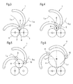
- FIGS. 3 to 6 show a plurality of winding phases of the winding process performed with the carrier roll winding machine 1 shown only schematically.
- FIG. 3 shows a winding phase during the beginning of the winding process.
- the loading roller 8 is initially arranged perpendicular or substantially perpendicular above the winding rollers 4, since the winding bed 7 due to the large diameter of the support rollers 5, 6 no place for an inclined Arrangement of the loading roller 8 relative to the winding rollers 4 leaves.
- the loading roller 12, however, is not yet at the winding rollers 4 at this winding phase for reasons of space.
- the movements of the loading rollers 8, 12 are shown in FIGS. 3 to 6 by means of so-called movement lines L 8 , L 12 .
- the loading roller 8 is then gradually led upwards due to the increase in diameter of the winding rollers 4 and the loading roller 12 is now applied to the winding rollers 4 at.
- FIG. 5 shows a winding phase of the further advanced winding process.
- both loading rollers 8, 12 are gradually led upwards due to the increase in diameter of the winding rollers 4 until they finally reach the position shown in Figure 6.
- This winding phase is basically the end of the winding process for the bobbins 4.
- a carrier roll winding machine of the aforementioned types is developed such that it has a higher stability and in which the operation is made safer by the invention.
Landscapes
- Winding Of Webs (AREA)
- Replacement Of Web Rolls (AREA)
- Rolls And Other Rotary Bodies (AREA)
Applications Claiming Priority (1)
| Application Number | Priority Date | Filing Date | Title |
|---|---|---|---|
| DE102005039303A DE102005039303A1 (de) | 2005-08-19 | 2005-08-19 | Tragwalzen-Wickelmaschine |
Publications (3)
| Publication Number | Publication Date |
|---|---|
| EP1757546A2 true EP1757546A2 (fr) | 2007-02-28 |
| EP1757546A3 EP1757546A3 (fr) | 2007-10-17 |
| EP1757546B1 EP1757546B1 (fr) | 2011-01-19 |
Family
ID=37393312
Family Applications (1)
| Application Number | Title | Priority Date | Filing Date |
|---|---|---|---|
| EP06115623A Not-in-force EP1757546B1 (fr) | 2005-08-19 | 2006-06-19 | Bobineuse à rouleaux porteurs |
Country Status (3)
| Country | Link |
|---|---|
| EP (1) | EP1757546B1 (fr) |
| AT (1) | ATE495991T1 (fr) |
| DE (2) | DE102005039303A1 (fr) |
Cited By (1)
| Publication number | Priority date | Publication date | Assignee | Title |
|---|---|---|---|---|
| EP1947042A1 (fr) | 2007-01-18 | 2008-07-23 | Reifenhäuser GmbH & Co. KG Maschinenfabrik | Machine d'enroulement |
Families Citing this family (2)
| Publication number | Priority date | Publication date | Assignee | Title |
|---|---|---|---|---|
| DE102006043628A1 (de) * | 2006-09-18 | 2008-03-27 | Voith Patent Gmbh | Wickelmaschine mit dämpfungsgeregelten Druckwalzen |
| CN117163704B (zh) * | 2023-10-31 | 2023-12-29 | 江苏正寰新材料科技有限公司 | 一种塑料薄膜加工用的压平装置 |
Citations (4)
| Publication number | Priority date | Publication date | Assignee | Title |
|---|---|---|---|---|
| EP0792245B1 (fr) | 1995-11-01 | 1999-06-09 | Valmet Corporation | Procede de bobinage |
| DE20013319U1 (de) | 2000-08-02 | 2000-09-28 | Voith Sulzer Papiertechnik Patent GmbH, 89522 Heidenheim | Bahnanfangsbefestigung |
| EP1375401A1 (fr) | 2002-06-25 | 2004-01-02 | A. CELLI NONWOVENS S.p.A. | Ré-enrouleuse avec des cylindres auxiliaires et méthode d'enroulement associée |
| DE19946400B4 (de) | 1999-09-28 | 2004-06-17 | Voith Paper Patent Gmbh | Verfahren zum Aufwickeln einer Materialbahn |
Family Cites Families (5)
| Publication number | Priority date | Publication date | Assignee | Title |
|---|---|---|---|---|
| US1868285A (en) * | 1929-01-09 | 1932-07-19 | Waterbury Tool Co | Winder drive for paper machines |
| US3064915A (en) * | 1958-06-27 | 1962-11-20 | Jagenberg Werke Ag | Machine for rewinding paper webs or similar materials |
| US4344585A (en) * | 1980-03-07 | 1982-08-17 | Paxall, Inc. | Sheet handling apparatus |
| DE4201327A1 (de) * | 1992-01-20 | 1993-07-22 | Feldmuehle Ag Stora | Wickelvorrichtung |
| DE10221962A1 (de) * | 2002-05-17 | 2003-11-27 | Voith Paper Patent Gmbh | Wickelvorrichtung |
-
2005
- 2005-08-19 DE DE102005039303A patent/DE102005039303A1/de not_active Withdrawn
-
2006
- 2006-06-19 EP EP06115623A patent/EP1757546B1/fr not_active Not-in-force
- 2006-06-19 DE DE502006008753T patent/DE502006008753D1/de active Active
- 2006-06-19 AT AT06115623T patent/ATE495991T1/de active
Patent Citations (4)
| Publication number | Priority date | Publication date | Assignee | Title |
|---|---|---|---|---|
| EP0792245B1 (fr) | 1995-11-01 | 1999-06-09 | Valmet Corporation | Procede de bobinage |
| DE19946400B4 (de) | 1999-09-28 | 2004-06-17 | Voith Paper Patent Gmbh | Verfahren zum Aufwickeln einer Materialbahn |
| DE20013319U1 (de) | 2000-08-02 | 2000-09-28 | Voith Sulzer Papiertechnik Patent GmbH, 89522 Heidenheim | Bahnanfangsbefestigung |
| EP1375401A1 (fr) | 2002-06-25 | 2004-01-02 | A. CELLI NONWOVENS S.p.A. | Ré-enrouleuse avec des cylindres auxiliaires et méthode d'enroulement associée |
Cited By (1)
| Publication number | Priority date | Publication date | Assignee | Title |
|---|---|---|---|---|
| EP1947042A1 (fr) | 2007-01-18 | 2008-07-23 | Reifenhäuser GmbH & Co. KG Maschinenfabrik | Machine d'enroulement |
Also Published As
| Publication number | Publication date |
|---|---|
| ATE495991T1 (de) | 2011-02-15 |
| EP1757546A3 (fr) | 2007-10-17 |
| DE502006008753D1 (de) | 2011-03-03 |
| DE102005039303A1 (de) | 2007-02-22 |
| EP1757546B1 (fr) | 2011-01-19 |
Similar Documents
| Publication | Publication Date | Title |
|---|---|---|
| DE3639244C2 (de) | Tragwalzenwickelapparat für bewegte Bahnen | |
| DE69508422T2 (de) | Wickelmaschine mit angehobener wickellaufschiene | |
| DE2727083C2 (de) | Hochleistungskalander zum Glätten und Satinieren einer Papierbahn | |
| EP0887294B1 (fr) | Machine à bobiner | |
| DE3221929C2 (de) | Doppeltragwalzen-Wickelmaschine | |
| EP1757546B1 (fr) | Bobineuse à rouleaux porteurs | |
| DE202009015980U1 (de) | Austauschvorrichtung zum Austauschen eines flexiblen Mantels, Bandes oder Siebes | |
| DE3916740C2 (de) | Textilmaschine mit verstellbarer Glättwalzenanordnung | |
| DE60009917T2 (de) | Verfahren zum kontinuierlichen aufwickeln von papier und wickler | |
| EP1739040B1 (fr) | Enrouleuse | |
| EP1710182A2 (fr) | Bobineuse à cylindres porteurs | |
| DE102005000052A1 (de) | Wickelmaschine | |
| DE19832067A1 (de) | Kalander für Bahnen aus Papier oder ähnlichem Material | |
| EP1086916B1 (fr) | Unité de palier pour rouleaux tendeurs de bandes de matériau | |
| EP1941096A1 (fr) | Rouleau deplisseur | |
| EP1683749B1 (fr) | Bobineuse avec cylindres porteurs | |
| EP0933320B1 (fr) | Bobineuse | |
| EP0918033B1 (fr) | Dispositif et procédé de bobinage pour l'enroulement de bandes de matériau | |
| EP1857389B1 (fr) | Bobineuse à deux rouleaux de support destinée à l'embobinage d'une bande de matériau | |
| DE29613350U1 (de) | Belastungswalzenanordnung | |
| DE102006018654A1 (de) | Doppeltragwalzen-Wickelmaschine zum Aufwickeln einer Materialbahn | |
| DE102008053467A1 (de) | Mit einem Druckwalzenbalken und einer Druckwalze versehener Aufroller vom Tragwalzentyp und Verfahren | |
| EP1757545B1 (fr) | Dispositif d'enroulement d'une bande | |
| AT505474B1 (de) | Hülsenverriegelungsvorrichtung | |
| EP2019060B1 (fr) | Dispositif d'enroulement et procédé d'enroulement de bandes de matière fibreuse dans un dispositif d'enroulement |
Legal Events
| Date | Code | Title | Description |
|---|---|---|---|
| PUAI | Public reference made under article 153(3) epc to a published international application that has entered the european phase |
Free format text: ORIGINAL CODE: 0009012 |
|
| AK | Designated contracting states |
Kind code of ref document: A2 Designated state(s): AT BE BG CH CY CZ DE DK EE ES FI FR GB GR HU IE IS IT LI LT LU LV MC NL PL PT RO SE SI SK TR |
|
| AX | Request for extension of the european patent |
Extension state: AL BA HR MK YU |
|
| PUAL | Search report despatched |
Free format text: ORIGINAL CODE: 0009013 |
|
| AK | Designated contracting states |
Kind code of ref document: A3 Designated state(s): AT BE BG CH CY CZ DE DK EE ES FI FR GB GR HU IE IS IT LI LT LU LV MC NL PL PT RO SE SI SK TR |
|
| AX | Request for extension of the european patent |
Extension state: AL BA HR MK YU |
|
| 17P | Request for examination filed |
Effective date: 20080417 |
|
| 17Q | First examination report despatched |
Effective date: 20080516 |
|
| AKX | Designation fees paid |
Designated state(s): AT DE FI IT |
|
| GRAP | Despatch of communication of intention to grant a patent |
Free format text: ORIGINAL CODE: EPIDOSNIGR1 |
|
| GRAS | Grant fee paid |
Free format text: ORIGINAL CODE: EPIDOSNIGR3 |
|
| GRAA | (expected) grant |
Free format text: ORIGINAL CODE: 0009210 |
|
| AK | Designated contracting states |
Kind code of ref document: B1 Designated state(s): AT DE FI IT |
|
| REF | Corresponds to: |
Ref document number: 502006008753 Country of ref document: DE Date of ref document: 20110303 Kind code of ref document: P |
|
| REG | Reference to a national code |
Ref country code: DE Ref legal event code: R096 Ref document number: 502006008753 Country of ref document: DE Effective date: 20110303 |
|
| PLBE | No opposition filed within time limit |
Free format text: ORIGINAL CODE: 0009261 |
|
| STAA | Information on the status of an ep patent application or granted ep patent |
Free format text: STATUS: NO OPPOSITION FILED WITHIN TIME LIMIT |
|
| 26N | No opposition filed |
Effective date: 20111020 |
|
| REG | Reference to a national code |
Ref country code: DE Ref legal event code: R097 Ref document number: 502006008753 Country of ref document: DE Effective date: 20111020 |
|
| PGFP | Annual fee paid to national office [announced via postgrant information from national office to epo] |
Ref country code: DE Payment date: 20120622 Year of fee payment: 7 |
|
| PGFP | Annual fee paid to national office [announced via postgrant information from national office to epo] |
Ref country code: FI Payment date: 20120613 Year of fee payment: 7 |
|
| PGFP | Annual fee paid to national office [announced via postgrant information from national office to epo] |
Ref country code: IT Payment date: 20120625 Year of fee payment: 7 |
|
| PGFP | Annual fee paid to national office [announced via postgrant information from national office to epo] |
Ref country code: AT Payment date: 20120613 Year of fee payment: 7 |
|
| REG | Reference to a national code |
Ref country code: AT Ref legal event code: MM01 Ref document number: 495991 Country of ref document: AT Kind code of ref document: T Effective date: 20130619 |
|
| PG25 | Lapsed in a contracting state [announced via postgrant information from national office to epo] |
Ref country code: FI Free format text: LAPSE BECAUSE OF NON-PAYMENT OF DUE FEES Effective date: 20130619 |
|
| REG | Reference to a national code |
Ref country code: DE Ref legal event code: R119 Ref document number: 502006008753 Country of ref document: DE Effective date: 20140101 |
|
| PG25 | Lapsed in a contracting state [announced via postgrant information from national office to epo] |
Ref country code: DE Free format text: LAPSE BECAUSE OF NON-PAYMENT OF DUE FEES Effective date: 20140101 |
|
| PG25 | Lapsed in a contracting state [announced via postgrant information from national office to epo] |
Ref country code: AT Free format text: LAPSE BECAUSE OF NON-PAYMENT OF DUE FEES Effective date: 20130619 Ref country code: IT Free format text: LAPSE BECAUSE OF NON-PAYMENT OF DUE FEES Effective date: 20130619 |