EP1757561A2 - Filtres à bassin - Google Patents
Filtres à bassin Download PDFInfo
- Publication number
- EP1757561A2 EP1757561A2 EP06254210A EP06254210A EP1757561A2 EP 1757561 A2 EP1757561 A2 EP 1757561A2 EP 06254210 A EP06254210 A EP 06254210A EP 06254210 A EP06254210 A EP 06254210A EP 1757561 A2 EP1757561 A2 EP 1757561A2
- Authority
- EP
- European Patent Office
- Prior art keywords
- compartment
- container
- water
- filter
- filter assembly
- Prior art date
- Legal status (The legal status is an assumption and is not a legal conclusion. Google has not performed a legal analysis and makes no representation as to the accuracy of the status listed.)
- Granted
Links
Images


Classifications
-
- C—CHEMISTRY; METALLURGY
- C02—TREATMENT OF WATER, WASTE WATER, SEWAGE, OR SLUDGE
- C02F—TREATMENT OF WATER, WASTE WATER, SEWAGE, OR SLUDGE
- C02F3/00—Biological treatment of water, waste water, or sewage
- C02F3/02—Aerobic processes
- C02F3/08—Aerobic processes using moving contact bodies
- C02F3/085—Fluidized beds
-
- Y—GENERAL TAGGING OF NEW TECHNOLOGICAL DEVELOPMENTS; GENERAL TAGGING OF CROSS-SECTIONAL TECHNOLOGIES SPANNING OVER SEVERAL SECTIONS OF THE IPC; TECHNICAL SUBJECTS COVERED BY FORMER USPC CROSS-REFERENCE ART COLLECTIONS [XRACs] AND DIGESTS
- Y02—TECHNOLOGIES OR APPLICATIONS FOR MITIGATION OR ADAPTATION AGAINST CLIMATE CHANGE
- Y02W—CLIMATE CHANGE MITIGATION TECHNOLOGIES RELATED TO WASTEWATER TREATMENT OR WASTE MANAGEMENT
- Y02W10/00—Technologies for wastewater treatment
- Y02W10/10—Biological treatment of water, waste water, or sewage
Definitions
- This invention relates to pond filters.
- An object of the present invention is to provide pond filters which alleviate at least some of the problems associated with prior art pond filters.
- a pond filter comprising a container for receiving at least one filtering element and for receiving water which is to be filtered, the container having an inlet for allowing water into the container and an outlet for allowing water out of the container.
- a pond filter assembly comprising a pond filter as defined above and at least one filtering element.
- a pond filter assembly comprising a container housing at least one filtering element and being arranged for receiving water which is to be filtered, the container having an inlet for allowing water into the container and an outlet for allowing water out of the container.
- the container comprises a plurality of compartments.
- the compartments may be arranged to receive respective, different types of filtering element.
- the compartments may house respective different types of filtering element.
- Different possible types of filtering elements include mechanical filtering elements; biological filter media elements, which may be static media elements or moveable media elements; UV filtering equipment.
- Each compartment may house or be arranged to house any one of or any combination of such filtering elements.
- One of the compartments may house/may be arranged to receive moveable media which can form part of a moving bed biological filter. Another of the compartments may house/may be arranged to receive at least one mechanical filtering element. Another of the compartments may house/may be arranged to receive static media which can form part of a biological filter.
- the compartment housing moveable media may have a water holding portion.
- the water holding portion may have a first volume and the total volume of the compartment occupied by the moveable media may be a second volume.
- the second volume is preferably smaller than the first volume.
- the compartment housing/arranged to receive moveable media may be arranged to promote circulation of the media within the compartment.
- One compartment for example the compartment housing/arranged to receive moveable media, may be separated from another compartment by a wall portion.
- Part of the wall portion may be solid.
- Another part of the wall portion may be perforated to allow flow of water from one compartment to the other.
- Part of the wall portion may be moulded as part of a main body of the container.
- Part of the wall portion may be distinct from a main body of the container.
- the distinct part is perforated to provide water flow paths.
- the distinct part may be arranged to clip or snap into position on the main body of the container.
- a hinged compartment boundary part may be provided having two portions joined via a hinge.
- the hinged part is typically distinct from the main body of the container.
- the hinge is typically a plastic hinge.
- a first of the two portions may be arranged to act as at least part of a wall separating one compartment from another.
- the second portion may be arranged as a cover for one of the compartments.
- the hinged part is installed in the region of a compartment housing/arranged to receive moveable media the hinged part may serve to retain the moveable media against leaving that compartment.
- the inlet into the container may be arranged for feeding water into the container tangentially relative to the container wall in the region of the inlet. This can help encourage circulation within the container.
- the inlet is provided into a compartment housing/arranged to receive moveable media.
- At least one air introduction venturi may be provided at the inlet into the container.
- the venturi may be arranged so that an axis of the venturi is generally tangentially to the side wall of the container in the region of the venturi.
- the venturi is disposed so that an outlet of the venturi feeds into a compartment housing/arranged to receive moveable media.
- Arranging the venturi so that the outlet from the venturi feeds a region of the filter containing moveable media is advantageous as this can maximise the oxygen available to bacteria growing on the moveable media.
- bacteria on moveable media which form part of a moving bed biological filter tend to grow aggressively and demand high levels of oxygen.
- the outlet from the container may have a relatively large overall diameter.
- the overall diameter of the outlet may be large enough that filter media housed by the container could pass through the outlet.
- the outlet may be provided with a guard to obstruct the passage of filter media from the container.
- the guard may comprise cross members which are integral with a main body of the container.
- the guard may be formed by virtue of the outlet being created by cutting out a plurality of selected portions of a side wall of the container, leaving cross members between the cut outs.
- the size of the cut outs may be chosen to be a such that filter media housed in the container in the region of the outlet cannot pass through the outlet.
- the outlet may be provided in a compartment housing/arranged to receive static filter media elements.
- the guard may be arranged to prevent the filter media elements from leaving the compartment via the outlet.
- the filter may be arranged to support at least one elongate mechanical filter element such as a piece of foam.
- the filter may comprise at least one mechanical filter element support onto which an elongate mechanical filter element may be mounted.
- the filter element support may comprise at least one water flow channel.
- the water flow channel may be arranged to receive water which has passed through a carried filter element and feed this towards an outlet of that part of the filter.
- the filter element support may comprise a perforated hollow tube. In such a case the water flow channel is provided by the hollow passage through the tube and the perforations allow access into the channel.
- the filter element support comprises an extrusion.
- the filter element support comprises at least one exposed water flow channel.
- Such an exposed water flow channel may be in the form of a groove in an outer surface of the support.
- the support comprises an extrusion which defines a plurality of exposed grooves.
- the filter may be provided with a cleaning kit which comprises at least one sleeve which is arranged to be located over one of the element supports during cleaning.
- the sleeve may be arranged to fit between the support and a supported filter element and further arranged to at least partially obstruct access to the water flow channel from the supported filter element. With such a sleeve in position the filter element, for example piece of foam may be squeezed to drive out debris without this debris exiting that portion of the filter via the water flow channel.
- the cleaning kit may comprise a plunger which is arranged for squeezing a filter element carried on the support.
- the plunger may comprise a tube portion arranged to receive the sleeve and a plate portion for acting on a filter element.
- a method of cleaning a pond filter assembly comprising a container housing at least one filtering element supported on a filter element support, which support comprises a water flow path for water leaving the filtering element, the method comprising the step of introducing a barrier between the filtering element and support to at least partially obstruct access to the water flow path before cleaning the filtering element.
- the barrier comprises a sleeve.
- the cleaning step may comprise squeezing the filtering element.
- a plunger may be used to squeeze the filtering element.
- the container may comprise at least one drain outlet.
- the drain outlet may be used when cleaning the filter - or "desludging". Where there are a plurality of compartments each compartment which does not comprise the main outlet may be provided with a respective drain outlet. In at least some circumstances the main outlet may be used as drain outlet, which relieves the need for a specific drain outlet in a compartment that comprises the main outlet. However, a drain outlet may be provided in addition to the main outlet in a respective compartment if that is desired.
- At least some of the compartments may comprise a floor portion.
- the floor portion may define one boundary of the compartment.
- the floor portion may be spaced from a base of the container.
- the floor portion of one compartment may act as a cover portion of another compartment.
- the floor portion of one compartment may separate that compartment from another compartment.
- the drain outlet of a compartment may be disposed in the sidewall of the container a position towards the level at which the floor portion is disposed.
- the floor portion may be arranged to encourage contents of the respective compartment to flow towards and out of the respective drain outlet when the drain outlet is open.
- the floor portion may be arranged so that when the filter is in its operative position, the upper surface of the floor portion slopes down towards the respective drain outlet.
- the upper surface of the floor portion may comprise channels for guiding flow towards the drain outlet.
- the floor portion may be arranged to provide a substantial seal against water flow from one compartment to another.
- the floor portion may provide an obstruction to sludge and/or media elements leaving the compartment, but not provide a water seal.
- a cleaning kit for use in cleaning a filter of the type defined above.
- the cleaning kit may comprise a sleeve as defined above and/or a plunger as defined above.
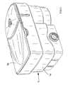
- FIG. 1 shows a pond filter in the form of a tank filter which embodies the present invention.
- This filter is a domestic pond filter for filtering water of, for example, a domestic fish pond.
- the pond filter comprises a container 1 which itself comprises a main body portion 1a and a lid portion 1b.
- the container 1 is arranged for housing filtering elements.
- the filter is arranged for housing a plurality of different types of filtering element, each type of filtering element being housed in a different respective compartment.
- the container 1 of the filter comprises an inlet arrangement 2 for allowing water to be fed into the container 1 for filtering and an outlet 3 for allowing filtered water to leave the container 1.
- the space within the container 1 is divided into a plurality of compartments 11, 12, 13.
- these first, second and third compartments 11, 12 and 13 are all disposed within the same container 1 and moreover are all respective parts of the space within the main body portion 1a of the container 1.
- all of these compartments are disposed within a single vessel. This removes the need for there to be separate units provided with connections therebetween as would be the case if separate filtering areas were provided in a more conventional way by providing separate vessels.
- the first of the compartments 11 comprises the inlet arrangement 2 and thus is arranged to receive water which is fed into the filter.
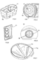
- the inlet arrangement 2 comprises a manifold 21 which can be seen in Figure 2 and which is shown in isolation in Figure 5.
- the manifold 21 is arranged to provide three inlet streams of water into the container 1. Each of these streams is fed through a respective aeration venturi 22 (these can be seen in Figure 2).
- Each venturi 22 is arranged to introduce air and hence oxygen into the water flowing into the filter.
- An air supply pipe (not shown) is connected to each venturi 2 to provide a supply of air to the venturi which can be sucked into and entrained into the water flow due to the reduction in pressure in the narrow portion of the venturi as water flows through it into the filter.
- the inlet arrangement 2, and in particular, the venturi 22 are orientated so that the water flow into the first compartment 11 of the filter is generally tangential to the side wall of that compartment in the region of the venturi 22.
- the venturi 22 are arranged in line with one another and each positioned at the same angle relative to the side wall of the compartment 11 in which they are disposed.
- the venturi 22 are arranged one above another so that they are also spaced the same distance from the side wall of the first compartment 11.
- the first compartment 11 is arranged to house movable media elements 41 schematically shown in Figure 2.
- These movable media elements 41 are commonly known as movable biomedia and are arranged to float in water provided in the first compartment 11 when the filter is in operation so as to provide what is known as a moving bed biological filter.
- the first compartment 11 has a water holding portion 11a which can be basically considered to be the bottom part of the compartment 11.
- the upper edge of the water holding portion 11 a is defined by a weir 11b formed at the top of a side wall portion 11c (part of which is cutaway in the drawing) which exists between the first compartment 11 and the second compartment 12.
- the movable biomedia 41 are arranged to float freely in the water provided in the water holding portion 11 a and also are provided in an amount such that the total volume occupied by the biomedia in the water holding portion 11a if there is no water present is significantly less than the overall volume defined by the water holding portion 11a. That is to say, when there is no water in the filter and if the correct number of moving biomedia 41 are provided in the water holding portion 11a with the filter in its normal operative position the biomedia 41 come to a level well below the weir 11b.
- the movable biomedia 41 comprise plastic elements which have a large surface area for their size over which bacteria can grow. In the moving bed these media continually knock against one another which has the effect of knocking the bacteria off of the media which encourages regrowth of younger and hence more effective bacteria.
- a perforated wall portion 11d is also provided between the first compartment 11 and the second compartment 12.
- This perforated wall portion 11d is arranged to retain the biomedia 41 in the first compartment, but allow water to flow from the first compartment 11 to the second compartment 12.
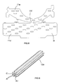
- the perforated wall portion 11d is part of a hinged compartment boundary part H which is shown in an unassembled state in Figure 8. Parts of, but not all of this hinged boundary part H may be seen in Figure 2.
- part of the perforated wall portion 11d may be seen in Figure 2 and part of a perforated cover portion 11e can be seen in Figure 2.
- the whole of the perforated wall portion 11d and perforated cover portion 11e can be seen in Figure 8.
- Those parts of the hinged compartment boundary part H which can be seen in Figure 2 are shown in their assembled configuration.
- the hinged compartment boundary part H as a whole helps to ensure that the moveable biomedia 41 are retained within the first compartment 11.
- the perforated wall portion 11d is joined to the cover portion 11e by a plastic hinge 11f which allows those two parts to hinge relative to one another between the unassembled state shown in Figure 8 and the assembled state shown in Figure 2.
- the two parts When in the assembled state shown in Figure 2 the two parts are held in the flexed position by virtue of being clipped together and also clipping into the main body portion 1a of the filter.
- the first compartment 11 also comprises a floor portion 11g which is shown in isolation in Figure 7.
- This floor portion 11g defines the lower surface of the first compartment 11.
- Figure 3 shows the main body portion 1a in an orientation where the location for the floor portion 11g can be seen and
- Figure 4 shows part of the main body portion 1a of the filter including the location for the floor portion 11g.
- the floor portion 11g is arranged to sit in this part of the main body portion and moreover it is arranged to sit in the main body spaced from and at an angle to the base of the main body portion 1a.
- the main body portion comprises a drain outlet 11h from the first compartment which is at a level that corresponds to the level at which the floor portion 11g rests in the region of the drain outlet 11h.
- the main body portion 1a of the filter and the floor portion 11g are arranged so that when the floor portion 11g is positioned in the filter, it is inclined (as mentioned above) with its lowest point coinciding with the position of the drain outlet 11h. This can help encourage material to leave the first compartment 11 via the drain outlet 11h when this is opened.
- the floor portion 11g is provided with a series of three channels 11i which further help to encourage the flow of material towards the drain outlet 11h.
- Figure 3 also shows the main body 1a of the filter and the location of the first compartment 11.
- the drain outlet 11h is useful when cleaning the first compartment. Water used in cleaning, water already in the filter and debris may be washed out of the drain outlet 11h. As will be clear, in normal use, the drain outlet is blocked off by a cap/plug (not shown).
- each block of foam 42 is supported in the second compartment 12 by a respective support rod 12a.
- One of the support rods 12a is shown in isolation in Figure 9.
- Each support rod 12a comprises a plastics extrusion.
- Each of the support rods 12a is mounted into a floor portion 12b of the second compartment 12. Again this floor portion 12b is shown partly been cut away in the drawing.
- Each extrusion comprises a plurality of arms A, in this embodiment eight arms. Between each adjacent pair of arms A there is formed a respective water channel C and each of the arms A terminates in a lip portion A1 to better support the foam block 42 to be carried by the support rod 12a.
- the support rods 12a are each mounted in the floor portion 12b in such a way that the way that the water channels C open out into the third compartment 13 which is disposed below the floor portion 12b of the second compartment 12. That is to say, each of the support rods 12a is mounted in or in register with an aperture provided in the floor portion 12b.
- This arrangement means that water which flows into the foam blocks 42 may flow through the flow blocks 42 reaching the water channel C provided in the support extrusion 12a and from there flow down these channels C and into the third compartment 13.
- the support rods can be in the form of hollow perforated tubes, i.e. tubes with perforations in their side walls. If this type of support rod is used the functioning of the device is much the same, but there is an increased risk of clogging of the perforations, there is an increased risk of snagging parts being generated in the production of these tubes which can catch and damage the foam and there is also a risk that the foam will be less than adequately supported such that it tends to squeeze into the perforations in the side walls of the tubes. Furthermore, the use of extrusions can help to reduce manufacturing costs.
- the second compartment 12 is provided with a drain output (not shown) which is similar to that 11h provided for the first compartment 11. Moreover this drain outlet (not shown) for the second compartment is again provided at a level which is substantially the same as that of the respective floor portion 12b of the second compartment 12. Thus, again the drain outlet is spaced from the base of the main body portion 1a. Again the floor portion 12b comprises channels (not shown) which are arranged to encourage flow of material out of the drain outlet when this is open. The provision of such a drain outlet again aids in cleaning the second compartment and its contents in the same way as the drain outlet 11h in the first compartment can help when cleaning of the first compartment and its contents.
- the third compartment 13 is defined between the floor portion 12b of the second compartment and the base of the main body 1a of the filter. It will be noted that the main body 1a of the filter can be considered to have two main chambers the first of which houses the first compartment 11 and the second which houses the second compartment 12 and the third compartment 13.
- the third compartment 13 is arranged to be filled with non-moving biomedia elements 43 which are schematically shown in Figure 2.
- the biomedia elements 43 are used to fill substantially the whole of the third compartment 13 to discourage movement of the media. This encourages growth of different types of bacteria with different beneficial cleaning effects than occur in the moving bed filter in the first compartment 11. Also at this point in the filter, the flow should be such that there is less agitation effect of the media than is the case in the first compartment 11.
- the present filter is arranged so that there is a plurality of compartments and at least one of these compartments is separated from at least one of the other compartments by virtue of a dividing portion which is integrally moulded with the main body of the container.
- the outlet 3 from the container 1 is disposed in a position such that it acts as an outlet from the third compartment 13. Furthermore, the overall diameter of the outlet 3 is relatively large and in particular it is larger than the size of the biomedia 43 which are housed in the third compartment 13 during use. Therefore, as can be seen in Figures 2 and 6, the outlet 3 is provided with a guard 31 in the form, in this embodiment, of four cross members 32. These cross members 32 are in this embodiment integral with the material of the main body portion 1a, that is to say the material of the side wall of the relevant compartment 13.
- the main body portion 1a is moulded with in effect a blanking disc across the inner end of the outlet 3 and then cut outs 33 are created by cutting out the relevant parts of material so as to leave the cross members 32.
- the provision of a guard in this way helps reduce manufacturing costs compared with the situation if a separate component is used as a guard.
- a cleaning kit may be provided with the filter.
- the cleaning kit comprises a sleeve 5 as shown in Figure 10 which is arranged to slide over one of the support rods 12a whilst the foam block 42 is in situ such that the sleeve 5 occupies a position between the foam block 42 and the support rod 12a.
- the foam may then be cleaned, for example by washing and/or squeezing, without the debris from the foam passing into the water channels C and hence into the third compartment 13 of the filter and potentially into the pond.
- the cleaning kit also comprises a plunger as shown in Figures 11 and 12.
- the plunger 6 comprises a handle 61, a tube portion 62 which is arranged to receive a support rod 12a surrounded by the sleeve 5 and a plate portion 53 which is arranged for squeezing a foam block carried by the support 12a/sleeve 5.
- this plunger is used to squeeze a foam block 42 which is carried by a support 12a which has been surrounded by the sleeve 5 as described above.
- the user may then operate the plunger 6 repeatedly up and down to drive water and debris out of the foam block 42 safe in the knowledge that at least the bulk of this debris is prevented from passing into the rest of the filter and hence ultimately prevented from returning to the pond.
- the present filter in common with conventional tank filters, is arranged to be situated "out of pond" that is to say situated out of the water which it is to filter. Furthermore it will be appreciated that the present filter is a non-sealed filter where the internal parts of the filter and in particular the compartment housing the moving media is open to atmospheric pressure. It will also be noted that there is no mechanical filtration in the filter before the inlet water reaches the moving media. This means that the energy from the water due to it being pumped into the filter can drive the movement of the moving media, without energy being lost in mechanical filtration. Mechanical filtration is provided after the water has passed through the moving media - the second compartment housing mechanical filtering elements is downstream of the first compartment housing the moving bed. The third compartment housing a static biological filter is downstream of the second compartment. Because the first biological filter is a moving bed it is not prone to becoming clogged and the mechanical filtration protects the second biological filter from clogging.
Landscapes
- Life Sciences & Earth Sciences (AREA)
- Water Supply & Treatment (AREA)
- Microbiology (AREA)
- Hydrology & Water Resources (AREA)
- Engineering & Computer Science (AREA)
- Environmental & Geological Engineering (AREA)
- Biodiversity & Conservation Biology (AREA)
- Chemical & Material Sciences (AREA)
- Organic Chemistry (AREA)
- Farming Of Fish And Shellfish (AREA)
- Biological Treatment Of Waste Water (AREA)
- Optical Filters (AREA)
- Holo Graphy (AREA)
- Crystals, And After-Treatments Of Crystals (AREA)
Applications Claiming Priority (1)
| Application Number | Priority Date | Filing Date | Title |
|---|---|---|---|
| GB0517257A GB0517257D0 (en) | 2005-08-23 | 2005-08-23 | Pond filters |
Publications (3)
| Publication Number | Publication Date |
|---|---|
| EP1757561A2 true EP1757561A2 (fr) | 2007-02-28 |
| EP1757561A3 EP1757561A3 (fr) | 2007-05-02 |
| EP1757561B1 EP1757561B1 (fr) | 2012-03-14 |
Family
ID=35198280
Family Applications (1)
| Application Number | Title | Priority Date | Filing Date |
|---|---|---|---|
| EP20060254210 Not-in-force EP1757561B1 (fr) | 2005-08-23 | 2006-08-10 | Filtres à bassin |
Country Status (3)
| Country | Link |
|---|---|
| EP (1) | EP1757561B1 (fr) |
| AT (1) | ATE549300T1 (fr) |
| GB (1) | GB0517257D0 (fr) |
Cited By (2)
| Publication number | Priority date | Publication date | Assignee | Title |
|---|---|---|---|---|
| GB2626640A (en) * | 2022-11-21 | 2024-07-31 | Evolution Aqua Ltd | Wastewater treatment method and apparatus |
| GB2635837A (en) * | 2023-11-21 | 2025-05-28 | Evolution Aqua Ltd | Wastewater treatment method and apparatus |
Family Cites Families (5)
| Publication number | Priority date | Publication date | Assignee | Title |
|---|---|---|---|---|
| DE9016202U1 (de) * | 1990-11-22 | 1991-03-28 | Meylahn, Gerd-Uwe, Dr., O-1501 Groß-Glienicke | Biofilter für die biologische Nitrifikation |
| DE4235330C1 (de) * | 1992-10-20 | 1993-09-30 | Fischtechnik Fredelsloh Dr Ger | Vorrichtung zum Reinigen von organisch belastetem Wasser |
| US5705057A (en) * | 1996-03-25 | 1998-01-06 | Hoffa; Gary | Fluidized bed biological filter assembly for fish tanks |
| GB9623362D0 (en) * | 1996-11-09 | 1997-01-08 | Goodson Malcolm G | Method and apparatus for water treatment |
| GB0120525D0 (en) * | 2001-08-23 | 2001-10-17 | Hozelock Ltd | Filter assemblies |
-
2005
- 2005-08-23 GB GB0517257A patent/GB0517257D0/en not_active Ceased
-
2006
- 2006-08-10 EP EP20060254210 patent/EP1757561B1/fr not_active Not-in-force
- 2006-08-10 AT AT06254210T patent/ATE549300T1/de active
Cited By (2)
| Publication number | Priority date | Publication date | Assignee | Title |
|---|---|---|---|---|
| GB2626640A (en) * | 2022-11-21 | 2024-07-31 | Evolution Aqua Ltd | Wastewater treatment method and apparatus |
| GB2635837A (en) * | 2023-11-21 | 2025-05-28 | Evolution Aqua Ltd | Wastewater treatment method and apparatus |
Also Published As
| Publication number | Publication date |
|---|---|
| EP1757561B1 (fr) | 2012-03-14 |
| GB0517257D0 (en) | 2005-10-05 |
| ATE549300T1 (de) | 2012-03-15 |
| EP1757561A3 (fr) | 2007-05-02 |
Similar Documents
| Publication | Publication Date | Title |
|---|---|---|
| US4098230A (en) | Aquarium | |
| JP5210042B2 (ja) | 水中生物飼育システムおよび水槽用浄化ユニット | |
| US5626747A (en) | Aquarium overflow filter system having a pre-overflow wall | |
| CN100527951C (zh) | 一种水族馆过滤器装置 | |
| KR20010029490A (ko) | 관상어 수조수의 여과 장치 | |
| US7425274B1 (en) | Aquarium filter unit | |
| US7631616B2 (en) | Aquarium | |
| JP6647534B1 (ja) | 浄水装置及び濾過ブロック | |
| KR101613063B1 (ko) | 수조용 여과기 및 이를 포함한 여과장치 | |
| US6352051B1 (en) | Egg-laying tank for home aquarium with egg protection arrangement | |
| KR101058492B1 (ko) | 활어수족관의 살균정수장치 및 이를 구비한 활어수족관 | |
| KR102312934B1 (ko) | 해마 치어 양식 수조 | |
| EP1757561B1 (fr) | Filtres à bassin | |
| US3540591A (en) | Filtering device for water tanks,particularly aquariums | |
| US7429321B2 (en) | Aquarium filter cartridge and filtration system | |
| KR200468432Y1 (ko) | 배수가 용이한 어항 | |
| EP3148326B1 (fr) | Dispositif de filtration pour aquariums et similaires | |
| US20110079555A1 (en) | Aquarium Filter | |
| KR102387473B1 (ko) | 수조의 정수장치 | |
| CN206629769U (zh) | 一种自沉淀鱼缸 | |
| CN212436976U (zh) | 一种鱼缸外置升流过滤系统 | |
| KR200207768Y1 (ko) | 수족관용 여과장치 | |
| JP3653014B2 (ja) | 水槽用濾過装置 | |
| JPS58163415A (ja) | 濾過装置 | |
| KR200327120Y1 (ko) | 순환여과식 수족관 |
Legal Events
| Date | Code | Title | Description |
|---|---|---|---|
| PUAI | Public reference made under article 153(3) epc to a published international application that has entered the european phase |
Free format text: ORIGINAL CODE: 0009012 |
|
| AK | Designated contracting states |
Kind code of ref document: A2 Designated state(s): AT BE BG CH CY CZ DE DK EE ES FI FR GB GR HU IE IS IT LI LT LU LV MC NL PL PT RO SE SI SK TR |
|
| AX | Request for extension of the european patent |
Extension state: AL BA HR MK YU |
|
| PUAL | Search report despatched |
Free format text: ORIGINAL CODE: 0009013 |
|
| AK | Designated contracting states |
Kind code of ref document: A3 Designated state(s): AT BE BG CH CY CZ DE DK EE ES FI FR GB GR HU IE IS IT LI LT LU LV MC NL PL PT RO SE SI SK TR |
|
| AX | Request for extension of the european patent |
Extension state: AL BA HR MK YU |
|
| RIC1 | Information provided on ipc code assigned before grant |
Ipc: B01D 24/36 20060101ALI20070329BHEP Ipc: C02F 3/12 20060101AFI20070329BHEP |
|
| 17P | Request for examination filed |
Effective date: 20071019 |
|
| 17Q | First examination report despatched |
Effective date: 20071121 |
|
| AKX | Designation fees paid |
Designated state(s): AT BE BG CH CY CZ DE DK EE ES FI FR GB GR HU IE IS IT LI LT LU LV MC NL PL PT RO SE SI SK TR |
|
| GRAP | Despatch of communication of intention to grant a patent |
Free format text: ORIGINAL CODE: EPIDOSNIGR1 |
|
| GRAS | Grant fee paid |
Free format text: ORIGINAL CODE: EPIDOSNIGR3 |
|
| GRAA | (expected) grant |
Free format text: ORIGINAL CODE: 0009210 |
|
| AK | Designated contracting states |
Kind code of ref document: B1 Designated state(s): AT BE BG CH CY CZ DE DK EE ES FI FR GB GR HU IE IS IT LI LT LU LV MC NL PL PT RO SE SI SK TR |
|
| REG | Reference to a national code |
Ref country code: GB Ref legal event code: FG4D |
|
| REG | Reference to a national code |
Ref country code: CH Ref legal event code: EP Ref country code: AT Ref legal event code: REF Ref document number: 549300 Country of ref document: AT Kind code of ref document: T Effective date: 20120315 |
|
| REG | Reference to a national code |
Ref country code: IE Ref legal event code: FG4D |
|
| REG | Reference to a national code |
Ref country code: NL Ref legal event code: T3 |
|
| REG | Reference to a national code |
Ref country code: DE Ref legal event code: R096 Ref document number: 602006028147 Country of ref document: DE Effective date: 20120510 |
|
| REG | Reference to a national code |
Ref country code: SE Ref legal event code: TRGR |
|
| PG25 | Lapsed in a contracting state [announced via postgrant information from national office to epo] |
Ref country code: LT Free format text: LAPSE BECAUSE OF FAILURE TO SUBMIT A TRANSLATION OF THE DESCRIPTION OR TO PAY THE FEE WITHIN THE PRESCRIBED TIME-LIMIT Effective date: 20120314 |
|
| LTIE | Lt: invalidation of european patent or patent extension |
Effective date: 20120314 |
|
| PG25 | Lapsed in a contracting state [announced via postgrant information from national office to epo] |
Ref country code: FI Free format text: LAPSE BECAUSE OF FAILURE TO SUBMIT A TRANSLATION OF THE DESCRIPTION OR TO PAY THE FEE WITHIN THE PRESCRIBED TIME-LIMIT Effective date: 20120314 Ref country code: LV Free format text: LAPSE BECAUSE OF FAILURE TO SUBMIT A TRANSLATION OF THE DESCRIPTION OR TO PAY THE FEE WITHIN THE PRESCRIBED TIME-LIMIT Effective date: 20120314 Ref country code: GR Free format text: LAPSE BECAUSE OF FAILURE TO SUBMIT A TRANSLATION OF THE DESCRIPTION OR TO PAY THE FEE WITHIN THE PRESCRIBED TIME-LIMIT Effective date: 20120615 |
|
| REG | Reference to a national code |
Ref country code: AT Ref legal event code: MK05 Ref document number: 549300 Country of ref document: AT Kind code of ref document: T Effective date: 20120314 |
|
| PG25 | Lapsed in a contracting state [announced via postgrant information from national office to epo] |
Ref country code: CY Free format text: LAPSE BECAUSE OF FAILURE TO SUBMIT A TRANSLATION OF THE DESCRIPTION OR TO PAY THE FEE WITHIN THE PRESCRIBED TIME-LIMIT Effective date: 20120314 |
|
| PG25 | Lapsed in a contracting state [announced via postgrant information from national office to epo] |
Ref country code: PL Free format text: LAPSE BECAUSE OF FAILURE TO SUBMIT A TRANSLATION OF THE DESCRIPTION OR TO PAY THE FEE WITHIN THE PRESCRIBED TIME-LIMIT Effective date: 20120314 Ref country code: SI Free format text: LAPSE BECAUSE OF FAILURE TO SUBMIT A TRANSLATION OF THE DESCRIPTION OR TO PAY THE FEE WITHIN THE PRESCRIBED TIME-LIMIT Effective date: 20120314 Ref country code: EE Free format text: LAPSE BECAUSE OF FAILURE TO SUBMIT A TRANSLATION OF THE DESCRIPTION OR TO PAY THE FEE WITHIN THE PRESCRIBED TIME-LIMIT Effective date: 20120314 Ref country code: CZ Free format text: LAPSE BECAUSE OF FAILURE TO SUBMIT A TRANSLATION OF THE DESCRIPTION OR TO PAY THE FEE WITHIN THE PRESCRIBED TIME-LIMIT Effective date: 20120314 Ref country code: RO Free format text: LAPSE BECAUSE OF FAILURE TO SUBMIT A TRANSLATION OF THE DESCRIPTION OR TO PAY THE FEE WITHIN THE PRESCRIBED TIME-LIMIT Effective date: 20120314 Ref country code: IS Free format text: LAPSE BECAUSE OF FAILURE TO SUBMIT A TRANSLATION OF THE DESCRIPTION OR TO PAY THE FEE WITHIN THE PRESCRIBED TIME-LIMIT Effective date: 20120714 |
|
| PG25 | Lapsed in a contracting state [announced via postgrant information from national office to epo] |
Ref country code: PT Free format text: LAPSE BECAUSE OF FAILURE TO SUBMIT A TRANSLATION OF THE DESCRIPTION OR TO PAY THE FEE WITHIN THE PRESCRIBED TIME-LIMIT Effective date: 20120716 Ref country code: SK Free format text: LAPSE BECAUSE OF FAILURE TO SUBMIT A TRANSLATION OF THE DESCRIPTION OR TO PAY THE FEE WITHIN THE PRESCRIBED TIME-LIMIT Effective date: 20120314 |
|
| PLBE | No opposition filed within time limit |
Free format text: ORIGINAL CODE: 0009261 |
|
| STAA | Information on the status of an ep patent application or granted ep patent |
Free format text: STATUS: NO OPPOSITION FILED WITHIN TIME LIMIT |
|
| PG25 | Lapsed in a contracting state [announced via postgrant information from national office to epo] |
Ref country code: DK Free format text: LAPSE BECAUSE OF FAILURE TO SUBMIT A TRANSLATION OF THE DESCRIPTION OR TO PAY THE FEE WITHIN THE PRESCRIBED TIME-LIMIT Effective date: 20120314 Ref country code: AT Free format text: LAPSE BECAUSE OF FAILURE TO SUBMIT A TRANSLATION OF THE DESCRIPTION OR TO PAY THE FEE WITHIN THE PRESCRIBED TIME-LIMIT Effective date: 20120314 |
|
| 26N | No opposition filed |
Effective date: 20121217 |
|
| PG25 | Lapsed in a contracting state [announced via postgrant information from national office to epo] |
Ref country code: IT Free format text: LAPSE BECAUSE OF FAILURE TO SUBMIT A TRANSLATION OF THE DESCRIPTION OR TO PAY THE FEE WITHIN THE PRESCRIBED TIME-LIMIT Effective date: 20120314 |
|
| REG | Reference to a national code |
Ref country code: CH Ref legal event code: PL |
|
| PG25 | Lapsed in a contracting state [announced via postgrant information from national office to epo] |
Ref country code: MC Free format text: LAPSE BECAUSE OF NON-PAYMENT OF DUE FEES Effective date: 20120831 |
|
| REG | Reference to a national code |
Ref country code: DE Ref legal event code: R097 Ref document number: 602006028147 Country of ref document: DE Effective date: 20121217 |
|
| PG25 | Lapsed in a contracting state [announced via postgrant information from national office to epo] |
Ref country code: ES Free format text: LAPSE BECAUSE OF FAILURE TO SUBMIT A TRANSLATION OF THE DESCRIPTION OR TO PAY THE FEE WITHIN THE PRESCRIBED TIME-LIMIT Effective date: 20120625 Ref country code: CH Free format text: LAPSE BECAUSE OF NON-PAYMENT OF DUE FEES Effective date: 20120831 Ref country code: LI Free format text: LAPSE BECAUSE OF NON-PAYMENT OF DUE FEES Effective date: 20120831 |
|
| REG | Reference to a national code |
Ref country code: IE Ref legal event code: MM4A |
|
| PG25 | Lapsed in a contracting state [announced via postgrant information from national office to epo] |
Ref country code: BG Free format text: LAPSE BECAUSE OF FAILURE TO SUBMIT A TRANSLATION OF THE DESCRIPTION OR TO PAY THE FEE WITHIN THE PRESCRIBED TIME-LIMIT Effective date: 20120614 Ref country code: IE Free format text: LAPSE BECAUSE OF NON-PAYMENT OF DUE FEES Effective date: 20120810 |
|
| REG | Reference to a national code |
Ref country code: DE Ref legal event code: R082 Ref document number: 602006028147 Country of ref document: DE Representative=s name: BOCKHORNI & KOLLEGEN PATENT- UND RECHTSANWAELT, DE Ref country code: DE Ref legal event code: R082 Ref document number: 602006028147 Country of ref document: DE Representative=s name: HEYER, VOLKER, DIPL.-PHYS. DR.RER.NAT., DE |
|
| PG25 | Lapsed in a contracting state [announced via postgrant information from national office to epo] |
Ref country code: TR Free format text: LAPSE BECAUSE OF FAILURE TO SUBMIT A TRANSLATION OF THE DESCRIPTION OR TO PAY THE FEE WITHIN THE PRESCRIBED TIME-LIMIT Effective date: 20120314 |
|
| REG | Reference to a national code |
Ref country code: DE Ref legal event code: R082 Ref document number: 602006028147 Country of ref document: DE Representative=s name: HEYER, VOLKER, DIPL.-PHYS. DR.RER.NAT., DE |
|
| PG25 | Lapsed in a contracting state [announced via postgrant information from national office to epo] |
Ref country code: HU Free format text: LAPSE BECAUSE OF FAILURE TO SUBMIT A TRANSLATION OF THE DESCRIPTION OR TO PAY THE FEE WITHIN THE PRESCRIBED TIME-LIMIT Effective date: 20060810 |
|
| REG | Reference to a national code |
Ref country code: DE Ref legal event code: R082 Ref document number: 602006028147 Country of ref document: DE Representative=s name: HEYER, VOLKER, DIPL.-PHYS. DR.RER.NAT., DE |
|
| REG | Reference to a national code |
Ref country code: DE Ref legal event code: R081 Ref document number: 602006028147 Country of ref document: DE Owner name: SA EXEL INDUSTRIES, FR Free format text: FORMER OWNER: HOZELOCK LTD., AYLESBURY, BUCKINGHAMSHIRE, GB Effective date: 20120321 Ref country code: DE Ref legal event code: R082 Ref document number: 602006028147 Country of ref document: DE Representative=s name: HEYER, VOLKER, DIPL.-PHYS. DR.RER.NAT., DE Effective date: 20140520 Ref country code: DE Ref legal event code: R081 Ref document number: 602006028147 Country of ref document: DE Owner name: SA EXEL INDUSTRIES, FR Free format text: FORMER OWNER: HOZELOCK LTD., HADDENHAM, AYLESBURY, BUCKINGHAMSHIRE, GB Effective date: 20150508 Ref country code: DE Ref legal event code: R082 Ref document number: 602006028147 Country of ref document: DE Representative=s name: HEYER, VOLKER, DIPL.-PHYS. DR.RER.NAT., DE Effective date: 20140421 Ref country code: DE Ref legal event code: R082 Ref document number: 602006028147 Country of ref document: DE Representative=s name: HEYER, VOLKER, DIPL.-PHYS. DR.RER.NAT., DE Effective date: 20150508 |
|
| REG | Reference to a national code |
Ref country code: GB Ref legal event code: 732E Free format text: REGISTERED BETWEEN 20150611 AND 20150617 |
|
| REG | Reference to a national code |
Ref country code: FR Ref legal event code: CA Effective date: 20150723 Ref country code: FR Ref legal event code: PLFP Year of fee payment: 10 |
|
| REG | Reference to a national code |
Ref country code: FR Ref legal event code: TP Owner name: SA EXEL INDUSTRIES, FR Effective date: 20150804 |
|
| REG | Reference to a national code |
Ref country code: FR Ref legal event code: PLFP Year of fee payment: 11 |
|
| REG | Reference to a national code |
Ref country code: FR Ref legal event code: PLFP Year of fee payment: 12 |
|
| REG | Reference to a national code |
Ref country code: FR Ref legal event code: PLFP Year of fee payment: 13 |
|
| PGFP | Annual fee paid to national office [announced via postgrant information from national office to epo] |
Ref country code: FR Payment date: 20200831 Year of fee payment: 15 |
|
| PGFP | Annual fee paid to national office [announced via postgrant information from national office to epo] |
Ref country code: SE Payment date: 20200812 Year of fee payment: 15 |
|
| PGFP | Annual fee paid to national office [announced via postgrant information from national office to epo] |
Ref country code: NL Payment date: 20210715 Year of fee payment: 16 |
|
| PGFP | Annual fee paid to national office [announced via postgrant information from national office to epo] |
Ref country code: LU Payment date: 20210721 Year of fee payment: 16 |
|
| PGFP | Annual fee paid to national office [announced via postgrant information from national office to epo] |
Ref country code: DE Payment date: 20210811 Year of fee payment: 16 |
|
| REG | Reference to a national code |
Ref country code: SE Ref legal event code: EUG |
|
| PG25 | Lapsed in a contracting state [announced via postgrant information from national office to epo] |
Ref country code: SE Free format text: LAPSE BECAUSE OF NON-PAYMENT OF DUE FEES Effective date: 20210811 |
|
| PG25 | Lapsed in a contracting state [announced via postgrant information from national office to epo] |
Ref country code: FR Free format text: LAPSE BECAUSE OF NON-PAYMENT OF DUE FEES Effective date: 20210831 |
|
| PGFP | Annual fee paid to national office [announced via postgrant information from national office to epo] |
Ref country code: GB Payment date: 20220818 Year of fee payment: 17 |
|
| PGFP | Annual fee paid to national office [announced via postgrant information from national office to epo] |
Ref country code: BE Payment date: 20220818 Year of fee payment: 17 |
|
| REG | Reference to a national code |
Ref country code: DE Ref legal event code: R119 Ref document number: 602006028147 Country of ref document: DE |
|
| REG | Reference to a national code |
Ref country code: NL Ref legal event code: MM Effective date: 20220901 |
|
| PG25 | Lapsed in a contracting state [announced via postgrant information from national office to epo] |
Ref country code: LU Free format text: LAPSE BECAUSE OF NON-PAYMENT OF DUE FEES Effective date: 20220810 |
|
| PG25 | Lapsed in a contracting state [announced via postgrant information from national office to epo] |
Ref country code: NL Free format text: LAPSE BECAUSE OF NON-PAYMENT OF DUE FEES Effective date: 20220901 |
|
| PG25 | Lapsed in a contracting state [announced via postgrant information from national office to epo] |
Ref country code: DE Free format text: LAPSE BECAUSE OF NON-PAYMENT OF DUE FEES Effective date: 20230301 |
|
| GBPC | Gb: european patent ceased through non-payment of renewal fee |
Effective date: 20230810 |
|
| REG | Reference to a national code |
Ref country code: BE Ref legal event code: MM Effective date: 20230831 |
|
| PG25 | Lapsed in a contracting state [announced via postgrant information from national office to epo] |
Ref country code: GB Free format text: LAPSE BECAUSE OF NON-PAYMENT OF DUE FEES Effective date: 20230810 |
|
| PG25 | Lapsed in a contracting state [announced via postgrant information from national office to epo] |
Ref country code: GB Free format text: LAPSE BECAUSE OF NON-PAYMENT OF DUE FEES Effective date: 20230810 |
|
| PG25 | Lapsed in a contracting state [announced via postgrant information from national office to epo] |
Ref country code: BE Free format text: LAPSE BECAUSE OF NON-PAYMENT OF DUE FEES Effective date: 20230831 |