EP1757744A2 - Bauelemnent zur Wärme-und/oder Schalldämmung - Google Patents
Bauelemnent zur Wärme-und/oder Schalldämmung Download PDFInfo
- Publication number
- EP1757744A2 EP1757744A2 EP06012139A EP06012139A EP1757744A2 EP 1757744 A2 EP1757744 A2 EP 1757744A2 EP 06012139 A EP06012139 A EP 06012139A EP 06012139 A EP06012139 A EP 06012139A EP 1757744 A2 EP1757744 A2 EP 1757744A2
- Authority
- EP
- European Patent Office
- Prior art keywords
- fire protection
- protection element
- component according
- envelope
- insulating body
- Prior art date
- Legal status (The legal status is an assumption and is not a legal conclusion. Google has not performed a legal analysis and makes no representation as to the accuracy of the status listed.)
- Withdrawn
Links
- 238000009413 insulation Methods 0.000 title claims description 12
- 239000011490 mineral wool Substances 0.000 claims abstract description 10
- 239000000463 material Substances 0.000 claims abstract description 6
- 239000011888 foil Substances 0.000 claims abstract description 3
- 230000003014 reinforcing effect Effects 0.000 claims description 5
- 238000003466 welding Methods 0.000 claims description 4
- 238000004026 adhesive bonding Methods 0.000 claims description 3
- 239000002184 metal Substances 0.000 claims description 2
- 239000012212 insulator Substances 0.000 abstract description 7
- 230000002787 reinforcement Effects 0.000 abstract description 4
- 230000032683 aging Effects 0.000 description 1
- 230000003679 aging effect Effects 0.000 description 1
- 238000010276 construction Methods 0.000 description 1
- 230000018109 developmental process Effects 0.000 description 1
- 230000007613 environmental effect Effects 0.000 description 1
- 230000010006 flight Effects 0.000 description 1
- 230000009969 flowable effect Effects 0.000 description 1
- 239000012774 insulation material Substances 0.000 description 1
- 239000002245 particle Substances 0.000 description 1
- 230000003068 static effect Effects 0.000 description 1
- 239000000126 substance Substances 0.000 description 1
Images



Classifications
-
- E—FIXED CONSTRUCTIONS
- E04—BUILDING
- E04B—GENERAL BUILDING CONSTRUCTIONS; WALLS, e.g. PARTITIONS; ROOFS; FLOORS; CEILINGS; INSULATION OR OTHER PROTECTION OF BUILDINGS
- E04B1/00—Constructions in general; Structures which are not restricted either to walls, e.g. partitions, or floors or ceilings or roofs
- E04B1/003—Balconies; Decks
- E04B1/0038—Anchoring devices specially adapted therefor with means for preventing cold bridging
Definitions
- the invention relates to a component for thermal and / or acoustic insulation between two components, in particular between a building part and a supported component, consisting of an insulating body to be arranged between the two components with these traversing and connectable to both components reinforcing elements and a fire protection element.
- Such components for thermal and / or acoustic insulation are for example from the DE 296 05 209.4 known and consist of a reinforcing elements within a joint surrounding insulating body, which is surrounded on its outer side by a fire collar made of mineral wool, so as to protect the reinforcement from heat and / or fire and thus to maintain the static substance of the associated building even after a fire ,
- fire protection elements have not only proven itself, but is now also prescribed and there is - especially after several years of experience with such fire protection elements - now the need for further development of components for thermal and / or acoustic insulation with fire protection collars and further improve.
- the fire protection element has a weather or aging protection in the form of a sheath that surrounds the fire protection element conveniently on all sides and seamlessly tight and so against the weather and other aging effects protects, which would affect the fire protection properties of the fire protection elements.
- the enclosure is suitably made of foil or plate material and is made in particular of plastic or metal, wherein the enclosure is closed by gluing, welding or similar types of connection.
- the envelope in a cylindrical shape, so that it can be cut to a predefinable length and closed by end caps, as a result of which the fire protection element and the envelope itself can still be processed on the construction site.
- the fire protection element is arranged with the sheath above and / or below the insulating body and extends parallel to the longitudinal extent of the insulating on the top and / or bottom, whereby the gap left between the two components sealed upwards and / or down and thus the reinforcement running through the joint can be protected accordingly.
- the fire protection element can also be arranged laterally of the insulating body and thus form, for example together with upper and lower fire protection elements a circumferential fire protection.
- the fire protection element itself is concerned, it is mat or plate-shaped in the usual manner and consists of mineral wool.
- the fire protection element consists of smaller, for example, flowable particles, the enclosure provides the necessary and adapted to the insulator shape.
- intumescent elements can be combined with other insulation materials and filled into the envelope, so that there are completely new possibilities with regard to the fire protection elements.
- Figure 1 shows a structural element for thermal and / or acoustic insulation 1 with a substantially cuboid insulating body 2 and the insulating body passing substantially horizontally extending reinforcing elements 3.
- the insulating body is covered on its upper side and on its underside with a fire protection element 4, 5 , which in each case has the same longitudinal and transverse extent as the insulating body 2, see for example also Figure 1a with the detail Z of Figure 1.
- Figure 2 shows a fire protection element 4a consisting of a mineral wool mat 6 and a sheath 7 of a plastic sheath which is formed like a tube and welded at both ends of the ends of the mineral wool mat and thereby closed.
- welded connections 8 can be seen from the perspective top view in FIG. 2 a), from the side view in FIG. 2 b) and from the front view in FIG. 2 c).
- FIG. 3 shows an alternative embodiment of a fire protection element 4b, in which a mineral wool mat 6 with an envelope 9 in the form of a plastic sheath is sealed off from the environment.
- This plastic sheath has the processing shown in the plan view in Figure 3b settlement, wherein the cuboid shape of the plastic sheath according to the perspective Top view in Figure 3a is produced by welding the abutting edges.
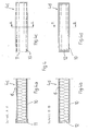
- FIG. 4 shows in four different representations further possibilities for the design of a fire protection element 4c, 4d.
- mineral wool mats 6 are surrounded by a plastic jacket 10, wherein FIG. 4a shows in vertical section and FIG. 4c a front view of a variant with an outer closure cap 11 which is pushed from outside over the plastic jacket and fixed there by gluing or welding.
- Figure 4b is shown in vertical section and in Figure 4d in front view of a similar embodiment with a plastic shell 10 which is closed by an inner cap 12, wherein the cap 12 to the cylindrical plastic shell 10, which has a matched to the mineral wool mat 6 rectangular cross-sectional shape , is fixed.
- a device for thermal and / or acoustic insulation 13 is shown in side view with a cuboid insulator 14, reinforcing elements 15 and a fire protection element 16.
- the special feature of this fire protection element is the fact that it consists of four individual elements 16a, 16b, 16c , 16d, which have as cover a plastic sheath (similar to the fire protection elements 4c and 4d) having a mineral wool core and the surface 14a of the insulator 14, on the left side 14b, the bottom 14c and the right side 14d abut flat.
- the four individual fire protection elements are connected to a circumferential fire protection element, the insulator 14 on all sides (except for the adjacent concrete components acted upon front and back) surrounds and thus protects the component for heat and / or sound insulation in all joints directions from fire and heat.
- a structural element for thermal and / or acoustic insulation is provided by the present invention, which has a holding and weather-resistant fire protection element, wherein the fire protection element is protected by simple means against environmental influences.
- Such a fire protection element can be used, for example, for components for thermal insulation in cantilevered exterior parts as well as, for example, components for sound insulation for flights of stairs, staircases and the like or for other applications in which joints and in particular by joints extending reinforcements must be protected from fire.
Landscapes
- Engineering & Computer Science (AREA)
- Architecture (AREA)
- Physics & Mathematics (AREA)
- Electromagnetism (AREA)
- Civil Engineering (AREA)
- Structural Engineering (AREA)
- Building Environments (AREA)
Abstract
Description
- Die Erfindung betrifft ein Bauelement zur Wärme- und/oder Schalldämmung zwischen zwei Bauteilen, insbesondere zwischen einem Gebäudeteil und einem getragenen Bauteil, bestehend aus einem zwischen den beiden Bauteilen anzuordnenden Isolierkörper mit diesen durchquerenden und an beide Bauteile anschließbaren Bewehrungselementen und aus einem Brandschutzelement.
- Derartige Bauelemente zur Wärme- und/oder Schalldämmung sind beispielsweise aus der
DE 296 05 209.4 bekannt und bestehen aus einem Bewehrungselemente innerhalb einer Fuge umgebenden Isolierkörper, der auf seiner Außenseite von einer Brandschutzmanschette aus Mineralwolle umgeben ist, um so die Bewehrung vor Hitze- und/oder Feuereinwirkung zu schützen und damit die statische Substanz des zugehörigen Gebäudes selbst nach einem Brand aufrechtzuerhalten. - Der Einsatz von Brandschutzelementen hat sich nicht nur bewährt, sondern wird mittlerweile auch vorgeschrieben und es besteht - insbesondere nach mehrjährigen Erfahrungen mit solchen Brandschutzelementen - nun Bedarf dafür, Bauelemente zur Wärme- und/oder Schalldämmung mit Brandschutzmanschetten weiterzuentwickeln und weiter zu verbessern.
- Diese Aufgabe wird erfindungsgemäß dadurch gelöst, dass das Brandschutzelement einen Witterungs- oder Alterungsschutz in Form einer Umhüllung aufweist, die das Brandschutzelement zweckmäßigerweise allseits und lückenlos dicht umgibt und so vor Witterungseinflüssen und sonstigen Alterungseffekten schützt, die die Brandschutzeigenschaften der Brandschutzelemente beeinträchtigen würden.
- Die Umhüllung besteht zweckmäßigerweise aus Folien- oder Plattenmaterial und ist insbesondere aus Kunststoff oder Metall hergestellt, wobei die Umhüllung durch Kleben, Verschweißen oder ähnliche Verbindungsarten verschlossen wird. Hierbei ist es auch möglich, die Umhüllung zylinderförmig auszubilden, so dass sie auf ein vorgebbares Längenmaß ablängbar und durch Endkappen verschließbar ist, wodurch das Brandschutzelement und die Umhüllung selbst noch auf der Baustelle verarbeitet werden kann.
- Zweckmäßigerweise ist das Brandschutzelement mit der Umhüllung oberhalb und/oder unterhalb des Isolierkörpers angeordnet und erstreckt sich parallel zu der Längserstreckung des Isolierkörpers auf dessen Ober- und/oder Unterseite, wodurch die zwischen den beiden Bauteilen belassene Fuge nach oben und/oder unten abgeschottet und damit die durch die Fuge verlaufende Bewehrung entsprechend geschützt werden kann. Außerdem kann das Brandschutzelement auch seitlich des Isolierkörpers angeordnet werden und so beispielsweise zusammen mit oberen und unteren Brandschutzelementen einen umlaufenden Brandschutz bilden.
- Was das Brandschutzelement selbst betrifft, so ist diese in der üblichen Art und Weise matten- oder plattenförmig ausgebildet und besteht aus Mineralwolle. Durch die Umhüllung ist es aber darüber hinaus auch möglich, dass das Brandschutzelement aus kleineren beispielsweise schüttbaren Teilchen besteht, wobei die Umhüllung für die nötige und an den Isolierkörper angepasste Form sorgt. Damit lassen sich beispielsweise Intumeszenz-Elemente mit anderen Dämmstoffmaterialien kombinieren und in die Umhüllung einfüllen, so dass dadurch hinsichtlich der Brandschutzelemente ganz neue Möglichkeiten bestehen.
- Weitere Merkmale und Vorteile der vorliegenden Erfindung ergeben sich aus der nachfolgenden Beschreibung von Ausführungsbeispielen anhand der Zeichnungen; hierbei zeigen
- Fig. 1
- ein erfindungsgemäßes Bauelement zur Wärme- und/oder Schalldämmung in perspektivischer Draufsicht;
- Fig. 1 a
- ein Detail Z aus Figur 1;
- Fig. 2
- eine schematische Darstellung eines Brandschutzelementes mit Umhüllung gemäß der vorliegenden Erfindung in perspektivischer Draufsicht, in Seitenansicht sowie in Vorderansicht;
- Fig. 3
- eine alternative Bauform eines Brandschutzelementes mit Umhüllung in perspektivischer Draufsicht mit abgewickelter Umhüllung;
- Fig. 4
- eine weitere Bauform eines Brandschutzelementes mit Umhüllung in geschnittener Seitenansicht sowie in Vorderansicht; und
- Fig. 5
- eine Bauform eines umlaufenden Brandschutzelementes.
- Figur 1 zeigt ein Bauelement zur Wärme- und/oder Schalldämmung 1 mit einem im wesentlichen quaderförmigen Isolierkörper 2 und den Isolierkörper durchquerenden im Wesentlichen in horizontaler Ebene verlaufenden Bewehrungselementen 3. Der Isolierkörper ist auf seiner Oberseite sowie auf seiner Unterseite mit einem Brandschutzelement 4, 5 bedeckt, welches jeweils dieselbe Längs- und Quererstreckung wie der Isolierkörper 2 aufweist, siehe beispielsweise auch Figur 1a mit dem Detail Z aus Figur 1.
- Mögliche Ausführungsformen dieser Brandschutzelemente 4, 5 sind in den Figuren 2 bis 4 näher dargestellt: Figur 2 zeigt ein Brandschutzelement 4a bestehend aus einer Mineralwollematte 6 und einer Umhüllung 7 aus einer Kunststoffhülle, die schlauchartig ausgebildet ist und an den Enden beidseits der Längsenden der Mineralwollematte verschweißt und dadurch verschlossen ist. Diese Schweißverbindungen 8 sind aus der perspektivischen Draufsicht in Figur 2a), aus der Seitenansicht in Figur 2b) und aus der Vorderansicht in Figur 2c) ersichtlich.
- In Figur 3 ist eine alternative Ausführungsform eines Brandschutzelementes 4b dargestellt, bei der eine Mineralwollematte 6 mit einer Umhüllung 9 in Form eines Kunststoffmantels gegenüber der Umgebung abgeschottet ist. Dieser Kunststoffmantel weist die aus der Draufsicht in Figur 3b ersichtliche Abwicklung auf, wobei die Quaderform des Kunststoffmantels gemäß der perspektivischen Draufsicht in Figur 3a durch Verschweißen der aneinander anstoßenden Kanten hergestellt wird.
- Figur 4 zeigt in vier verschiedenen Darstellungen weitere Möglichkeiten zur Ausgestaltung eines Brandschutzelementes 4c, 4d. Auch hier sind Mineralwollematten 6 von einem Kunststoffmantel 10 umgeben, wobei Figur 4a im Vertikalschnitt und Figur 4c in Vorderansicht eine Variante zeigt mit einer außenliegenden Verschlusskappe 11, die von außen über den Kunststoffmantel geschoben und dort durch Verklebungen oder Verschweißung fixiert ist. In Figur 4b ist im Vertikalschnitt und in Figur 4d in Vorderansicht eine ähnliche Ausführungsform mit einem Kunststoffmantel 10 dargestellt, der über eine innenliegende Verschlusskappe 12 verschlossen ist, wobei die Verschlusskappe 12 an den zylinderförmigen Kunststoffmantel 10, der eine an die Mineralwollematte 6 angepasste rechteckige Querschnittsform aufweist, festgelegt ist.
- In Figur 5 ist schließlich ein Bauelement zur Wärme- und/oder Schalldämmung 13 in Seitenansicht dargestellt mit einem quaderförmigen Isolierkörper 14, Bewehrungselementen 15 und einem Brandschutzelement 16. Das Besondere an diesem Brandschutzelement ist die Tatsache, dass es aus vier Einzelelementen 16a, 16b, 16c, 16d besteht, die als Umhüllung einen Kunststoffmantel (ähnlich wie die Brandschutzelemente 4c und 4d) aufweisen mit einem Mineralwollekern und die an der Oberseite 14a des Isolierkörpers 14, an der linken Seite 14b, der Unterseite 14c sowie der rechten Seite 14d flächig anliegen. Mit insgesamt vier in den jeweiligen Ecken des Isolierkörpers 14 angeordneten Verbindungswinkeln 17a, 17b, 17c, 17d sind die vier Brandschutz-Einzelelemente zu einem umlaufenden Brandschutzelement verbunden, das den Isolierkörper 14 allseits (mit Ausnahme der von den angrenzenden Betonbauteilen beaufschlagten Vorder- und Rückseite) umgibt und so das Bauelement zur Wärme- und/oder Schalldämmung in allen Fugenrichtungen vor Feuer und Hitze schützt.
- Zusammenfassend wird durch die vorliegende Erfindung ein Bauelement zur Wärme- und/oder Schalldämmung zur Verfügung gestellt, das ein halterungs- und witterungsbeständiges Brandschutzelement aufweist, wobei das Brandschutzelement mit einfachen Mitteln vor Umgebungseinflüssen geschützt ist.
- Ein solches Brandschutzelement lässt sich beispielsweise für Bauelemente zur Wärmedämmung bei vorkragenden Außenteilen ebenso anwenden wie beispielsweise bei Bauelementen zur Schalldämmung für Treppenläufe, Treppenpodeste und dergleichen oder auch für weitere Anwendungsmöglichkeiten, bei denen Fugen und insbesondere sich durch Fugen erstreckende Bewehrungen vor Feuer geschützt werden müssen.
Claims (11)
- Bauelement zur Wärme- und/oder Schalldämmung zwischen zwei Bauteilen, insbesondere zwischen einem Gebäudeteil und einem getragenen Bauteil, bestehend aus einem zwischen den beiden Bauteilen anzuordnenden Isolierkörper (2, 14) mit diesen durchquerenden Bewehrungselementen (3, 15) und mit zumindest einem Brandschutzelement (4, 5, 4a, 4b, 4c, 4d, 16, 16a, 16b, 16c, 16d),
dadurch gekennzeichnet,
dass das Brandschutzelement eine Umhüllung (7, 9, 10) aufweist. - Bauelement nach zumindest Anspruch 1,
dadurch gekennzeichnet,
dass die Umhüllung (7, 9, 10) das Brandschutzelement (4, 5, 4a, 4b, 4c, 16, 16a - 16d) allseitig umgibt. - Bauelement nach zumindest einem der vorstehenden Ansprüche,
dadurch gekennzeichnet,
dass die Umhüllung (7, 9, 10) das Brandschutzelement (4, 5, 4a bis 4d, 16, 16a - 16d) lückenlos umgibt. - Bauelement nach zumindest einem der vorstehenden Ansprüche,
dadurch gekennzeichnet,
dass die Umhüllung (7, 9, 10) aus Folien- oder Plattenmaterial besteht. - Bauelement nach zumindest einem der vorstehenden Ansprüche,
dadurch gekennzeichnet,
dass die Umhüllung (7, 9, 10) durch Kleben oder Verschweißen verschließbar ist. - Bauelement nach zumindest einem der vorstehenden Ansprüche,
dadurch gekennzeichnet,
dass die Umhüllung (7, 9, 10) aus Kunststoff oder Metall besteht. - Bauelement nach zumindest einem der vorstehenden Ansprüche,
dadurch gekennzeichnet,
dass die Umhüllung (10) zylinderförmig ausgebildet, auf ein vorgebbares Längenmaß ablängbar und durch Endkappen (11, 12, 17a, 17b, 17c, 17d) verschließbar ist. - Bauelement nach zumindest einem der vorstehenden Ansprüche,
dadurch gekennzeichnet,
dass das Brandschutzelement (4, 5 4a bis 4d, 16, 16c) mit der Umhüllung oberhalb und/oder unterhalb des Isolierkörpers (2, 14) angeordnet ist und sich parallel zu der Längserstreckung des Isolierkörpers auf dessen Ober- (14c) und/oder Unterseite erstreckt. - Bauelement nach zumindest einem der vorstehenden Ansprüche,
dadurch gekennzeichnet,
dass das Brandschutzelement (16) aus vier Einzelelementen (16a bis 16d) besteht, die an der Oberseite (14a), der Unterseite (14c), sowie den beiden vertikalen Außenseiten (14b, 14d) angeordnet sind und ein umlaufendes Brandschutzelement bilden. - Bauelement nach zumindest einem der vorstehenden Ansprüche,
dadurch gekennzeichnet,
dass das Brandschutzelement (4, 5, 4a bis 4d) einen Kern (6) aus matten- oder plattenförmigen Material und insbesondere aus Mineralwolle aufweist. - Bauelement nach zumindest einem der vorstehenden Ansprüche,
dadurch gekennzeichnet,
dass das Brandschutzelement eine von der Umhüllung umgebene Füllung aus Brandschutzmaterial aufweist und dass die Füllung schüttbar ausgebildet ist.
Applications Claiming Priority (1)
| Application Number | Priority Date | Filing Date | Title |
|---|---|---|---|
| DE102005040170A DE102005040170A1 (de) | 2005-08-25 | 2005-08-25 | Bauelement zur Wärme- und/oder Schalldämmung |
Publications (2)
| Publication Number | Publication Date |
|---|---|
| EP1757744A2 true EP1757744A2 (de) | 2007-02-28 |
| EP1757744A3 EP1757744A3 (de) | 2008-03-05 |
Family
ID=37715409
Family Applications (1)
| Application Number | Title | Priority Date | Filing Date |
|---|---|---|---|
| EP06012139A Withdrawn EP1757744A3 (de) | 2005-08-25 | 2006-06-13 | Bauelemnent zur Wärme-und/oder Schalldämmung |
Country Status (7)
| Country | Link |
|---|---|
| US (1) | US20070074477A1 (de) |
| EP (1) | EP1757744A3 (de) |
| JP (1) | JP2007056667A (de) |
| CN (1) | CN1920198A (de) |
| CA (1) | CA2556609A1 (de) |
| DE (1) | DE102005040170A1 (de) |
| RU (1) | RU2006126337A (de) |
Cited By (2)
| Publication number | Priority date | Publication date | Assignee | Title |
|---|---|---|---|---|
| DE102023103051A1 (de) * | 2023-02-08 | 2024-08-08 | Max Frank GmbH & Co Kommanditgesellschaft | Anschlusselement für lasteinleitende Bauteile |
| EP4621151A1 (de) | 2024-03-20 | 2025-09-24 | Max Frank GmbH & Co. KG | Anschlusselement für lasteinleitende bauteile |
Families Citing this family (12)
| Publication number | Priority date | Publication date | Assignee | Title |
|---|---|---|---|---|
| DE102006011336A1 (de) * | 2006-03-09 | 2007-09-13 | Schöck Bauteile GmbH | Bauelement zur Wärmedämmung |
| DE102009003749B4 (de) * | 2009-04-06 | 2020-07-23 | Max Frank Gmbh & Co. Kg | Verbundwerkstoff zur Erstellung einer Brandschutzfuge |
| CH701351A1 (de) | 2009-06-24 | 2010-12-31 | Stefan Schweizer | Kragplattenanschlusselement. |
| DE202010015743U1 (de) * | 2010-11-24 | 2012-03-01 | Vector Foiltec Gmbh | Gebäudeumhüllungselement mit thermischem Isolierelement |
| CN104481042B (zh) * | 2014-12-15 | 2016-09-21 | 中山市诚盛建材开发有限公司 | 一种扣板及应用扣板的建筑用隔声隔热结构 |
| US10787809B2 (en) * | 2015-03-23 | 2020-09-29 | Jk Worldwide Enterprises Inc. | Thermal break for use in construction |
| CA3036302C (en) * | 2016-09-12 | 2021-06-08 | Jk Worldwide Enterprises Inc. | Thermal break for use in construction |
| DE102016124736A1 (de) * | 2016-12-19 | 2018-06-21 | Schöck Bauteile GmbH | Bauelement zur Wärmedämmung |
| RU177349U1 (ru) * | 2017-12-12 | 2018-02-16 | Михаил Александрович Дрыкин | Теплоизолирующая вставка для стыков элементов строительных конструкций |
| GB201819196D0 (en) * | 2018-11-26 | 2019-01-09 | Ancon Ltd | Building element, system and method |
| DE202019100581U1 (de) * | 2019-01-31 | 2020-05-04 | Hartmann Hauke | Gebäude mit einer Wand und einer auf dieser Wand aufliegenden Decke, Gebäude mit einer Wand, Bewehrungselement, Bewehrungsbauteil und Bewehrungsbaugruppe |
| KR102348485B1 (ko) * | 2020-07-06 | 2022-01-07 | 주식회사 정양에스지 | 단열유니트 내부에 전단근이 내재 되고 인장근과 전단근이 일체화된 단열구조체 |
Citations (2)
| Publication number | Priority date | Publication date | Assignee | Title |
|---|---|---|---|---|
| DE29605209U1 (de) | 1995-03-24 | 1996-05-15 | Schöck Bauteile GmbH, 76534 Baden-Baden | Fugenplatte |
| EP0892118A1 (de) | 1997-07-19 | 1999-01-20 | SCHÖCK BAUTEILE GmbH | Bauelement zur Wärmedämmung |
Family Cites Families (6)
| Publication number | Priority date | Publication date | Assignee | Title |
|---|---|---|---|---|
| US4182085A (en) * | 1978-05-17 | 1980-01-08 | Elson Jesse M | Method and structure for insulating a wall or ceiling |
| US6131352A (en) * | 1995-01-26 | 2000-10-17 | Barnes; Vaughn | Fire barrier |
| DE19711187A1 (de) * | 1997-03-18 | 1998-09-24 | Schoeck Bauteile Gmbh | System zur Wärmedämmung |
| US6058668A (en) * | 1998-04-14 | 2000-05-09 | Herren; Thomas R. | Seismic and fire-resistant head-of-wall structure |
| DE10019014A1 (de) * | 2000-04-17 | 2001-10-18 | Mea Meisinger Stahl & Kunststo | Wärmedämmendes, Brandgeschütztes Anschlussbauteil zum Anschluss eines Getragenen an ein Tragendes Bauteil und Verfahren zur Verbindung des Anschlussbauteils mit dem Getragenen oder Tragenden Bauteil |
| US6698146B2 (en) * | 2001-10-31 | 2004-03-02 | W. R. Grace & Co.-Conn. | In situ molded thermal barriers |
-
2005
- 2005-08-25 DE DE102005040170A patent/DE102005040170A1/de not_active Ceased
-
2006
- 2006-06-13 EP EP06012139A patent/EP1757744A3/de not_active Withdrawn
- 2006-07-21 RU RU2006126337/03A patent/RU2006126337A/ru not_active Application Discontinuation
- 2006-08-21 US US11/465,838 patent/US20070074477A1/en not_active Abandoned
- 2006-08-22 CA CA002556609A patent/CA2556609A1/en not_active Abandoned
- 2006-08-24 JP JP2006227829A patent/JP2007056667A/ja active Pending
- 2006-08-25 CN CNA2006101265151A patent/CN1920198A/zh active Pending
Patent Citations (2)
| Publication number | Priority date | Publication date | Assignee | Title |
|---|---|---|---|---|
| DE29605209U1 (de) | 1995-03-24 | 1996-05-15 | Schöck Bauteile GmbH, 76534 Baden-Baden | Fugenplatte |
| EP0892118A1 (de) | 1997-07-19 | 1999-01-20 | SCHÖCK BAUTEILE GmbH | Bauelement zur Wärmedämmung |
Cited By (3)
| Publication number | Priority date | Publication date | Assignee | Title |
|---|---|---|---|---|
| DE102023103051A1 (de) * | 2023-02-08 | 2024-08-08 | Max Frank GmbH & Co Kommanditgesellschaft | Anschlusselement für lasteinleitende Bauteile |
| EP4414511A1 (de) | 2023-02-08 | 2024-08-14 | Max Frank GmbH & Co. KG | Anschlusselement für lasteinleitende bauteile |
| EP4621151A1 (de) | 2024-03-20 | 2025-09-24 | Max Frank GmbH & Co. KG | Anschlusselement für lasteinleitende bauteile |
Also Published As
| Publication number | Publication date |
|---|---|
| DE102005040170A1 (de) | 2007-03-01 |
| US20070074477A1 (en) | 2007-04-05 |
| JP2007056667A (ja) | 2007-03-08 |
| CN1920198A (zh) | 2007-02-28 |
| CA2556609A1 (en) | 2007-02-25 |
| RU2006126337A (ru) | 2008-01-27 |
| EP1757744A3 (de) | 2008-03-05 |
Similar Documents
| Publication | Publication Date | Title |
|---|---|---|
| EP2653625B1 (de) | Thermisch isolierendes Bauelement | |
| EP1757744A2 (de) | Bauelemnent zur Wärme-und/oder Schalldämmung | |
| WO2017093221A1 (de) | Schalelement und deckenschalung mit einem solchen schalelement | |
| CH707947A1 (de) | Bauteil, Verfahren zur Verbindung von Holzelementen, Computerprogramm. | |
| CH662403A5 (de) | Profil. | |
| CH680600A5 (en) | Wooden building of composite box section parts - has plywood outside walls with flat connectors in central layer | |
| EP2998454B1 (de) | Bauelement zum verbinden von zwei durch eine fuge getrennten gebäudeteilen | |
| EP1592852B1 (de) | Verlorener schalungsk rper | |
| DE102006053721B4 (de) | Industriell vorgefertigtes Gebäudeelement und Formvorrichtung zu dessen Herstellung | |
| CH670670A5 (de) | ||
| EP3315678B1 (de) | Fertigbauteil zum anschluss einer betonkragplatte an ein bauwerk | |
| WO1986006122A1 (fr) | Ensemble d'elements prefabriques pour structures a portiques | |
| DE20303405U1 (de) | Wärmedämmelement | |
| CH669005A5 (de) | Daemmeinrichtung, insbesondere fuer die schalldaemmung, sowie daemmplatte fuer die einrichtung. | |
| DE102023110939B3 (de) | Flächenhaftes Paneel und Verfahren zum Herstellen eines derartigen Paneels | |
| DE3017904A1 (de) | Fassadenelement | |
| DE19722051A1 (de) | Modulares Bauelementsystem zur Wärmedämmung | |
| DE10060528B4 (de) | Schubkraft-Verbindung im Fertigteilbau | |
| DE4406820C2 (de) | Deckenlager für eine auf einer Mauerwerksaußenwand aufliegende Stahlbetondecke | |
| DE19833032A1 (de) | Tür | |
| AT502603B1 (de) | Verbundstütze | |
| DE10225535B4 (de) | Mit einer Beplankung versehender Holzrahmen | |
| DE102009057752B4 (de) | Vorgefertigtes Wandelement | |
| EP1647643A1 (de) | Bewehreinrichtung zur Verbindung zweier Bauteile | |
| EP1878840A2 (de) | Bauelement zur Wärmedämmung zwischen zwei zu betonierenden Bauteilen |
Legal Events
| Date | Code | Title | Description |
|---|---|---|---|
| PUAI | Public reference made under article 153(3) epc to a published international application that has entered the european phase |
Free format text: ORIGINAL CODE: 0009012 |
|
| AK | Designated contracting states |
Kind code of ref document: A2 Designated state(s): AT BE BG CH CY CZ DE DK EE ES FI FR GB GR HU IE IS IT LI LT LU LV MC NL PL PT RO SE SI SK TR |
|
| AX | Request for extension of the european patent |
Extension state: AL BA HR MK YU |
|
| PUAL | Search report despatched |
Free format text: ORIGINAL CODE: 0009013 |
|
| AK | Designated contracting states |
Kind code of ref document: A3 Designated state(s): AT BE BG CH CY CZ DE DK EE ES FI FR GB GR HU IE IS IT LI LT LU LV MC NL PL PT RO SE SI SK TR |
|
| AX | Request for extension of the european patent |
Extension state: AL BA HR MK YU |
|
| 17P | Request for examination filed |
Effective date: 20080607 |
|
| 17Q | First examination report despatched |
Effective date: 20080710 |
|
| AKX | Designation fees paid |
Designated state(s): AT BE BG CH CY CZ DE DK EE ES FI FR GB GR HU IE IS IT LI LT LU LV MC NL PL PT RO SE SI SK TR |
|
| STAA | Information on the status of an ep patent application or granted ep patent |
Free format text: STATUS: THE APPLICATION IS DEEMED TO BE WITHDRAWN |
|
| 18D | Application deemed to be withdrawn |
Effective date: 20090825 |