EP1757786A2 - Turbocompresseur à capacité variable et procédé de fabrication des éléments constitutifs du mécanisme de variation - Google Patents
Turbocompresseur à capacité variable et procédé de fabrication des éléments constitutifs du mécanisme de variation Download PDFInfo
- Publication number
- EP1757786A2 EP1757786A2 EP06119587A EP06119587A EP1757786A2 EP 1757786 A2 EP1757786 A2 EP 1757786A2 EP 06119587 A EP06119587 A EP 06119587A EP 06119587 A EP06119587 A EP 06119587A EP 1757786 A2 EP1757786 A2 EP 1757786A2
- Authority
- EP
- European Patent Office
- Prior art keywords
- drive ring
- nozzle
- lever plates
- connection pin
- lever
- Prior art date
- Legal status (The legal status is an assumption and is not a legal conclusion. Google has not performed a legal analysis and makes no representation as to the accuracy of the status listed.)
- Granted
Links
Images

Classifications
-
- F—MECHANICAL ENGINEERING; LIGHTING; HEATING; WEAPONS; BLASTING
- F02—COMBUSTION ENGINES; HOT-GAS OR COMBUSTION-PRODUCT ENGINE PLANTS
- F02B—INTERNAL-COMBUSTION PISTON ENGINES; COMBUSTION ENGINES IN GENERAL
- F02B37/00—Engines characterised by provision of pumps driven at least for part of the time by exhaust
- F02B37/12—Control of the pumps
- F02B37/22—Control of the pumps by varying cross-section of exhaust passages or air passages, e.g. by throttling turbine inlets or outlets or by varying effective number of guide conduits
-
- F—MECHANICAL ENGINEERING; LIGHTING; HEATING; WEAPONS; BLASTING
- F01—MACHINES OR ENGINES IN GENERAL; ENGINE PLANTS IN GENERAL; STEAM ENGINES
- F01D—NON-POSITIVE DISPLACEMENT MACHINES OR ENGINES, e.g. STEAM TURBINES
- F01D17/00—Regulating or controlling by varying flow
- F01D17/10—Final actuators
- F01D17/12—Final actuators arranged in stator parts
- F01D17/14—Final actuators arranged in stator parts varying effective cross-sectional area of nozzles or guide conduits
- F01D17/16—Final actuators arranged in stator parts varying effective cross-sectional area of nozzles or guide conduits by means of nozzle vanes
- F01D17/165—Final actuators arranged in stator parts varying effective cross-sectional area of nozzles or guide conduits by means of nozzle vanes for radial flow, i.e. the vanes turning around axes which are essentially parallel to the rotor centre line
-
- F—MECHANICAL ENGINEERING; LIGHTING; HEATING; WEAPONS; BLASTING
- F01—MACHINES OR ENGINES IN GENERAL; ENGINE PLANTS IN GENERAL; STEAM ENGINES
- F01D—NON-POSITIVE DISPLACEMENT MACHINES OR ENGINES, e.g. STEAM TURBINES
- F01D17/00—Regulating or controlling by varying flow
- F01D17/02—Arrangement of sensing elements
- F01D17/04—Arrangement of sensing elements responsive to load
-
- F—MECHANICAL ENGINEERING; LIGHTING; HEATING; WEAPONS; BLASTING
- F02—COMBUSTION ENGINES; HOT-GAS OR COMBUSTION-PRODUCT ENGINE PLANTS
- F02B—INTERNAL-COMBUSTION PISTON ENGINES; COMBUSTION ENGINES IN GENERAL
- F02B37/00—Engines characterised by provision of pumps driven at least for part of the time by exhaust
- F02B37/12—Control of the pumps
-
- F—MECHANICAL ENGINEERING; LIGHTING; HEATING; WEAPONS; BLASTING
- F05—INDEXING SCHEMES RELATING TO ENGINES OR PUMPS IN VARIOUS SUBCLASSES OF CLASSES F01-F04
- F05D—INDEXING SCHEME FOR ASPECTS RELATING TO NON-POSITIVE-DISPLACEMENT MACHINES OR ENGINES, GAS-TURBINES OR JET-PROPULSION PLANTS
- F05D2220/00—Application
- F05D2220/40—Application in turbochargers
-
- F—MECHANICAL ENGINEERING; LIGHTING; HEATING; WEAPONS; BLASTING
- F05—INDEXING SCHEMES RELATING TO ENGINES OR PUMPS IN VARIOUS SUBCLASSES OF CLASSES F01-F04
- F05D—INDEXING SCHEME FOR ASPECTS RELATING TO NON-POSITIVE-DISPLACEMENT MACHINES OR ENGINES, GAS-TURBINES OR JET-PROPULSION PLANTS
- F05D2230/00—Manufacture
- F05D2230/20—Manufacture essentially without removing material
- F05D2230/21—Manufacture essentially without removing material by casting
- F05D2230/211—Manufacture essentially without removing material by casting by precision casting, e.g. microfusing or investment casting
-
- F—MECHANICAL ENGINEERING; LIGHTING; HEATING; WEAPONS; BLASTING
- F05—INDEXING SCHEMES RELATING TO ENGINES OR PUMPS IN VARIOUS SUBCLASSES OF CLASSES F01-F04
- F05D—INDEXING SCHEME FOR ASPECTS RELATING TO NON-POSITIVE-DISPLACEMENT MACHINES OR ENGINES, GAS-TURBINES OR JET-PROPULSION PLANTS
- F05D2230/00—Manufacture
- F05D2230/30—Manufacture with deposition of material
- F05D2230/31—Layer deposition
- F05D2230/313—Layer deposition by physical vapour deposition
-
- F—MECHANICAL ENGINEERING; LIGHTING; HEATING; WEAPONS; BLASTING
- F05—INDEXING SCHEMES RELATING TO ENGINES OR PUMPS IN VARIOUS SUBCLASSES OF CLASSES F01-F04
- F05D—INDEXING SCHEME FOR ASPECTS RELATING TO NON-POSITIVE-DISPLACEMENT MACHINES OR ENGINES, GAS-TURBINES OR JET-PROPULSION PLANTS
- F05D2230/00—Manufacture
- F05D2230/30—Manufacture with deposition of material
- F05D2230/31—Layer deposition
- F05D2230/314—Layer deposition by chemical vapour deposition
-
- F—MECHANICAL ENGINEERING; LIGHTING; HEATING; WEAPONS; BLASTING
- F05—INDEXING SCHEMES RELATING TO ENGINES OR PUMPS IN VARIOUS SUBCLASSES OF CLASSES F01-F04
- F05D—INDEXING SCHEME FOR ASPECTS RELATING TO NON-POSITIVE-DISPLACEMENT MACHINES OR ENGINES, GAS-TURBINES OR JET-PROPULSION PLANTS
- F05D2230/00—Manufacture
- F05D2230/90—Coating; Surface treatment
-
- Y—GENERAL TAGGING OF NEW TECHNOLOGICAL DEVELOPMENTS; GENERAL TAGGING OF CROSS-SECTIONAL TECHNOLOGIES SPANNING OVER SEVERAL SECTIONS OF THE IPC; TECHNICAL SUBJECTS COVERED BY FORMER USPC CROSS-REFERENCE ART COLLECTIONS [XRACs] AND DIGESTS
- Y10—TECHNICAL SUBJECTS COVERED BY FORMER USPC
- Y10T—TECHNICAL SUBJECTS COVERED BY FORMER US CLASSIFICATION
- Y10T29/00—Metal working
- Y10T29/49—Method of mechanical manufacture
- Y10T29/49316—Impeller making
- Y10T29/4932—Turbomachine making
Definitions
- the present invention is applied to exhaust turbochargers for internal combustion engines and relates to the construction of a drive ring and lever plates of a variable-throat exhaust turbocharger equipped with a variable throat mechanism for varying the blade angle of a plurality of nozzle vanes and to an assembling method of the variable throat mechanism.
- the drive ring is disposed adjacent to the nozzle mount in axial direction between the side face of the lever plate and the side face of the nozzle mount, but there is disclosed no countermeasure to prevent slipping-off of the drive ring from the nozzle mount towards the lever plate side.
- said drive ring is disposed between said lever plates and nozzle mount side by side with the lever plates and nozzle mount in axial direction thereof, and a connection pin part or parts are formed protruding from a side face of the lever plate or the drive ring and integral with the material of the lever plate or the drive ring, whereby the connection pin parts of the lever plates or pin parts of the drive ring are engaged into the grooves of the drive pins or grooves of the lever plates.
- connection pin part of each of the lever plates or parts of the drive ring can be easily formed integral with each of the lever plates or drive ring by extrusion consisting of one stage of processing or by precision casting while attaining high durability of the contact surfaces of the connection pin parts and grooves by increasing the hardness of the contact surfaces to suppress abrasion of the contact surfaces, with the result that assembling man-hours and assembling cost can be reduced and the number of parts and manufacturing cost of the parts can be reduced compared with a variable threat mechanism in which the connection pins are provided separately and fixed to the lever plates or drive ring.
- said drive ring is disposed between said lever plates and nozzle mount side by side with the lever plates and nozzle mount in axial direction thereof, and rivets are fixed to the nozzle mount at its outer side face so that the outer side face of the drive ring can comes into contact with the seating faces of the rivets thereby to prevent the drive ring from moving axially.
- recesses are formed to stride across the outer side face of the drive ring and outer side face of the nozzle mount and the head of each of the rivets is received in each of the recesses.
- said drive ring is disposed between said lever plates and nozzle mount side by side with the lever plates and nozzle mount in axial direction thereof, and a plurality of partial circumferential grooves are provided at the outer side part of the nozzle mount, thereby receiving the drive ring in the partial circumferential grooves and preventing the drive ring from moving in axial direction.
- the drive ring can be positively prevented from slipping out in axial direction by such a manner that require no additional part and therefore does not result in increase in the number of parts and cost, by engaging the drive ring in the partial circumferential grooves formed at the side part of the nozzle mount, and occurrence of fail in action of the variable throat mechanism can be prevented.
- a coating layer is formed either on the surface of the connection pin part or on the surface of the groove into which the connecting part is engaged by PVD processing (physical vapor deposition processing) or by CVD(chemical vapor deposition processing).
- the wear resistance of the contact surface is increased.
- the drive ring can be positively prevented from slipping out in axial direction and occurrence of fail in action of the variable throat mechanism can be prevented, by such an extremely compact and cost saving manner as to fix a plurality of rivets to a side face of the nozzle mount, or by such a manner that requires no additional part and therefore does not result in increase in the number of parts and cost by engaging the drive ring into the partial circumferential grooves formed at a side part of the nozzle mount.
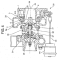
- the turbine shaft connecting the turbine rotor 34 to the compressor 35 is supported rotatably by the bearing housing 36 by means of two bearings 37, 37.
- Reference numeral 8 is an exhaust gas outlet, 40 is an axis of rotation of the exhaust turbo charger.
- Reference numeral 41 is an actuator
- 33 is an actuator rod
- 39 is a drive mechanism connecting the actuator rod 33 to a driving ring 3
- the drive mechanism converts reciprocating movement of the actuator rod into rotational movement of the drive ring.
- Reference numeral 100 is a variable throat mechanism for varying the blade angle of the nozzle vanes 2.
- variable-throat exhaust turbocharger equipped with the variable throat mechanism constructed as shown in FIG.5
- exhaust gas from an internal combustion engine(not shown in the drawing) enters the scroll 38 to flow along the volute of the scroll 38.
- the exhaust gas flows through passages between the nozzle vanes 2 into the turbine rotor 34 from the outer periphery thereof to flow radially inwardly exerting expansion work on the turbine rotor 34 to be exhausted in axial direction through the exhaust gas outlet 8 to the outside.
- Control of the variable-throat turbocharger is carried out by the actuator 41 which acts to change the blade angle of the nozzle vanes 2 to an angle position so that the exhaust gas flows through the passage between the nozzle vanes 2 at a desired flow rate, said blade angle being determined by a blade angle control means not shown in the drawing.
- Reciprocal displacement of the actuator rod 33 is converted to rotational displacement of the drive ring by the medium of the drive mechanism 39.
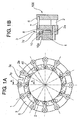
- Reference numeral 3 is a drive ring formed into an annular shape and supported rotatably by a nozzle mount 5. Grooves 3y are provided at the peripheral part of the drive ring 3 at equal spacing, each of connecting pin parts 10 explained later is engaged with each of the grooves. Reference numeral 3z is a driving groove with which a link of the drive mechanism 39 is engaged.
- Each of the lever plates 1 has a connecting pin part 10 formed on its face at the circumferentially outward side, and the nozzle shaft 2a of the nozzle vane 2 is fixed to the lever plate 1 at the inward side thereof.
- the lever plate 1 is disposed in the axially outer side(exhaust gas outlet side 8 in FIG.5), and the drive ring 3 is disposed between a side face of the lever plate 1 and a side face of the nozzle mount 5 side by side with the lever plates 1 and nozzle mount 5 in axial direction thereof.
- the connecting pin part 10 is formed by extrusion, in which a spot on a flat face of the lever plate 1 is pressed by a pressing machine to form a depressed portion 10a thereon to obtain a cylindrical projecting part on the other side flat face thereof, thus the connecting pin part 10 is formed in one piece with parent material, i.e. the lever plate 1.
- FIG.2A is a front view of the second embodiment of the variable throat mechanism of the present invention viewed from the lever plate side
- FIG.2B is a sectional view along line A-A in FIG.2A.
- the connecting pin parts 10(11) can be easily formed integral with the parent material by using as material of the lever plate 1 or the drive ring 3 steel material tough but relatively soft and easy to process by extrusion and applying extrusion forming to either the lever plate 1 or drive ring 3, or by precision casting.
- connection pin parts 10(11) or the grooves, into which the connection pin parts 10(11) are to be engaged with surface hardening including diffusion coating, their contact surfaces are increased in hardness and the occurrence of adhesion between the surfaces of the grooves and the connecting pin parts is prevented, with the result that abrasion of the contact surface of the connecting pin parts 10 (or 11) and grooves 3y (or 1b) can be reduced.
- connection pin parts 10 or parts 11 can be easily formed integral with each of the lever plates 1 or drive ring 3 by extrusion consisting of one stage of processing or by precision casting while attaining high durability of the contact surface by increasing the hardness of the contact surfaces of connection parts 10(or 11) and grooves 3y(or 1b) to suppress wear of the contact surfaces, with the result that assembling man-hours and assembling cost can be reduced and the number of parts and manufacturing cost of the parts can be reduced compared with a variable threat mechanism in which the connection pins are provided separately and fixed to the lever plates or drive ring.
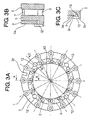
- FIG.3A is a front view of the third embodiment of the variable throat mechanism of the present invention viewed from the lever plate side
- FIG.3B is a sectional view along line A-A in FIG.3A
- FIG.3C is a sectional view as along line C-C in FIG.3A of a modification of the third embodiment.
- a section along line A-A in FIG.3A of the third embodiment is the same as that shown in FIG.1B and FIG.2B.
- a drive ring 3 is disposed between the side face of the lever plate 1 and the a side face of a nozzle mount 5 side by side with the lever plates 1 and nozzle mount 5 in axial direction thereof as is in the case of the first and second embodiment, and a plurality of rivets 12 are fixed to the nozzle mount 5 at its outer side face so that the outer side face 3a of the drive ring 3 can come into contact with the seating faces of the rivets 12 thereby to prevent the drive ring from slipping out towards the lever plate side.
- recesses 13 are formed to stride across the outer side face 3c of the drive ring 3 and outer side face 5c of the nozzle mount 5, and the head of each of the rivets is received in each of the recesses thereby to evade the heads of the rivets from protruding than the outer side face of the lever plate 1.
- slipping out of the drive ring 3 in axial direction can be positively prevented by such an extremely compact, cost saving, and light-in-weight means as a plurality of rivets 12 (four rivets in the example shown in FIG.3A) fixed to a side face of the nozzle mount 5, with the result that occurrence of failed action of the nozzle throat mechanism 100 caused by slipping out of the drive ring 3 in the axial direction.
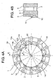
- FIG.4A is a front view of the second embodiment of the variable throat mechanism of the present invention viewed from the lever plate side
- FIG.4B is a sectional view along line D-D in FIG.4A.
- a section along line A-A in FIG.3A of the fourth embodiment is the same as that shown in FIG.1B.
- a plurality of engaging parts 14 which consists of a plurality of concave portions 14a formed on the inner periphery of the drive ring 3 and a plurality of convex portions 14b formed at the outer side face part 5z of the nozzle mount 5, the convex portions 14b forming outside walls of the partial circumferential grooves 15 and the bottoms of the partial circumferential grooves 15 coincide with the outer periphery of the stepped part of the nozzle mount 5.
- the drive ring 3 can be positively prevented from slipping out in axial direction by such a manner that requires no additional part and therefore does not result in increase in the number of parts and cost.
- a coating layer is formed either on the surface of the connection pin part 10 (or 11) or on the surface of the groove 3y(or 1b),(or on both the surfaces) by PVD processing(physical ion adsorption processing) or by CVD(chemical ion adsorption processing).
- the abrasive resistance of the contact surface is increased.
- a variable-throat exhaust turbocharger in which is used a means to reduce wear of the contact surfaces of the connecting pin parts which are formed integral with the lever plates or the drive ring and the grooves into which the connection pin parts are engaged, and which is provided a means to prevent slipping out of the drive ring from the nozzle mount toward the lever plate to prevent probable occurrence of fail in action of the variable nozzle mechanism caused by the slipping out of the drive ring.
Landscapes
- Engineering & Computer Science (AREA)
- Mechanical Engineering (AREA)
- General Engineering & Computer Science (AREA)
- Chemical & Material Sciences (AREA)
- Combustion & Propulsion (AREA)
- Supercharger (AREA)
- Control Of Turbines (AREA)
Applications Claiming Priority (1)
| Application Number | Priority Date | Filing Date | Title |
|---|---|---|---|
| JP2005243829A JP4545068B2 (ja) | 2005-08-25 | 2005-08-25 | 可変容量型排気ターボ過給機及び可変ノズル機構構成部材の製造方法 |
Publications (3)
| Publication Number | Publication Date |
|---|---|
| EP1757786A2 true EP1757786A2 (fr) | 2007-02-28 |
| EP1757786A3 EP1757786A3 (fr) | 2014-08-13 |
| EP1757786B1 EP1757786B1 (fr) | 2018-05-02 |
Family
ID=37462254
Family Applications (1)
| Application Number | Title | Priority Date | Filing Date |
|---|---|---|---|
| EP06119587.1A Not-in-force EP1757786B1 (fr) | 2005-08-25 | 2006-08-25 | Turbocompresseur à capacité variable et procédé de fabrication des éléments constitutifs du mécanisme de variation |
Country Status (6)
| Country | Link |
|---|---|
| US (1) | US7406826B2 (fr) |
| EP (1) | EP1757786B1 (fr) |
| JP (1) | JP4545068B2 (fr) |
| KR (1) | KR101330400B1 (fr) |
| CN (3) | CN101864996B (fr) |
| BR (1) | BRPI0605188B1 (fr) |
Cited By (6)
| Publication number | Priority date | Publication date | Assignee | Title |
|---|---|---|---|---|
| DE102008058509A1 (de) * | 2008-11-21 | 2010-05-27 | Bosch Mahle Turbo Systems Gmbh & Co. Kg | Ladeeinrichtung |
| DE102009014917A1 (de) * | 2009-03-25 | 2010-09-30 | Bosch Mahle Turbo Systems Gmbh & Co. Kg | Ladeeinrichtung |
| EP2067959A4 (fr) * | 2006-10-06 | 2012-01-25 | Tofuji E M I Co Ltd | Turbocompresseur |
| DE102013207440A1 (de) | 2013-04-24 | 2014-10-30 | Bosch Mahle Turbo Systems Gmbh & Co. Kg | Verfahren zur Herstellung eines Hebels einer variablen Turbinengeometrie |
| EP2180159A4 (fr) * | 2007-12-14 | 2015-06-03 | Mitsubishi Heavy Ind Ltd | Mécanisme de tuyère variable |
| EP2136048B1 (fr) | 2007-12-21 | 2018-12-19 | Mitsubishi Heavy Industries Engine & Turbocharger, Ltd. | Turbocompresseur d'échappement du type à capacité variable équipé d'un mécanisme de tuyère variable |
Families Citing this family (54)
| Publication number | Priority date | Publication date | Assignee | Title |
|---|---|---|---|---|
| US20110182717A1 (en) * | 2006-03-30 | 2011-07-28 | Borgwarner Inc. | Turbocharger |
| US7712311B2 (en) * | 2007-03-14 | 2010-05-11 | Gm Global Technology Operations, Inc. | Turbocharger assembly with catalyst coating |
| CN101896692B (zh) * | 2007-12-12 | 2014-03-12 | 霍尼韦尔国际公司 | 用于涡轮增压器的具有由径向构件定位的喷嘴环的可变喷嘴 |
| KR100968256B1 (ko) * | 2008-04-15 | 2010-07-06 | (주)계양정밀 | 가변노즐을 구비한 터보차져 |
| JP5109894B2 (ja) * | 2008-09-17 | 2012-12-26 | 株式会社Ihi | ターボチャージャ |
| JP5107223B2 (ja) * | 2008-12-26 | 2012-12-26 | 三菱重工業株式会社 | 可変ノズル機構および可変容量型排気ターボ過給機 |
| JP5010577B2 (ja) * | 2008-12-26 | 2012-08-29 | 三菱重工業株式会社 | 可変容量型排気ターボ過給機および可変容量型排気ターボ過給機の製造方法 |
| JP5010631B2 (ja) * | 2009-02-27 | 2012-08-29 | 三菱重工業株式会社 | 可変容量型排気ターボ過給機 |
| US8393858B2 (en) * | 2009-03-13 | 2013-03-12 | Honeywell International Inc. | Turbine shroud support coupling assembly |
| US9017017B2 (en) * | 2009-04-10 | 2015-04-28 | Honeywell Internatonal Inc. | Variable-vane assembly having fixed guide pins for unison ring |
| KR101031633B1 (ko) * | 2009-04-17 | 2011-04-27 | (주)계양정밀 | 가변 지오메트리 터보차져의 노즐어셈블리 및 그 제작방법 |
| KR101144515B1 (ko) | 2009-10-27 | 2012-05-11 | 현대자동차주식회사 | 가변 지오메트리 터보차져의 노즐어셈블리 |
| DE112010004597B4 (de) * | 2009-11-27 | 2022-05-25 | Borgwarner Inc. | Turbolader mit variabler Turbinengeometrie |
| WO2011068267A1 (fr) * | 2009-12-04 | 2011-06-09 | (주)계양정밀 | Dispositif à tuyère variable de turbocompresseur |
| US8668443B2 (en) * | 2010-01-08 | 2014-03-11 | Honeywell International Inc. | Variable-vane assembly having unison ring guided radially by rollers and fixed members, and restrained axially by one or more fixed axial stops |
| DE112011100758B4 (de) * | 2010-03-03 | 2022-10-06 | Borgwarner Inc. | Kostenreduzierter Turbolader mit variabler Geometrie mit gestanzter Verstellringanordnung |
| CN102207008B (zh) * | 2010-03-31 | 2014-10-22 | 杰锋汽车动力系统股份有限公司 | 一种涡轮增压器及提高涡轮增压器增压效率的方法 |
| IT1401665B1 (it) * | 2010-08-31 | 2013-08-02 | Nuova Pignone S R L | Sistema di azionamento per turbomacchina e metodo. |
| JP5591136B2 (ja) * | 2011-01-28 | 2014-09-17 | 大同特殊鋼株式会社 | 異形金属リングの製造方法 |
| JP5796302B2 (ja) * | 2011-02-09 | 2015-10-21 | 株式会社Ihi | 可変ノズルユニット及び可変容量型過給機 |
| CN102242645B (zh) * | 2011-07-21 | 2015-03-11 | 湖南天雁机械有限责任公司 | 涡轮增压器整体式可变喷嘴环 |
| JP5129882B1 (ja) * | 2011-09-28 | 2013-01-30 | 三菱重工業株式会社 | 可変ノズル機構を備えた可変容量型排気ターボ過給機 |
| JP5579145B2 (ja) | 2011-09-28 | 2014-08-27 | 三菱重工業株式会社 | ターボチャージャ用ノズルベーン開度規制ストッパ構造 |
| JP5193346B2 (ja) | 2011-09-28 | 2013-05-08 | 三菱重工業株式会社 | 可変ノズル機構を備えた可変容量型排気ターボ過給機 |
| JP5134717B1 (ja) | 2011-09-28 | 2013-01-30 | 三菱重工業株式会社 | 可変容量型ターボチャージャおよび可変ノズル機構の組付方法 |
| DE112013001516T5 (de) * | 2012-04-29 | 2014-12-04 | Borgwarner Inc. | Schaufelaggregatanordnung mit abschleifbarer Beschichtung für VTG-Turbolader |
| DE102012106789B4 (de) * | 2012-07-26 | 2022-10-27 | Ihi Charging Systems International Gmbh | Verstellbarer Leitapparat für eine Turbine, Turbine für einen Abgasturbolader und Abgasturbolader |
| WO2014050530A1 (fr) | 2012-09-28 | 2014-04-03 | 株式会社Ihi | Unité à buse variable, compresseur à capacité variable et procédé de fabrication d'éléments de transmission de puissance |
| US9745861B2 (en) | 2012-11-20 | 2017-08-29 | Borgwarner Inc. | Exhaust-gas turbocharger |
| JP6163789B2 (ja) * | 2013-03-01 | 2017-07-19 | 株式会社Ihi | 可変ノズルユニット及び可変容量型過給機 |
| JP6107395B2 (ja) * | 2013-05-09 | 2017-04-05 | 株式会社Ihi | 可変ノズルユニット及び可変容量型過給機 |
| WO2015001927A1 (fr) | 2013-07-04 | 2015-01-08 | 株式会社Ihi | Mécanisme de transmission de puissance d'actionneur et turbocompresseur |
| CN103527264B (zh) * | 2013-11-01 | 2016-04-20 | 汉美综合科技(常州)有限公司 | 滑动式喷嘴 |
| CN104162631B (zh) * | 2014-04-25 | 2017-01-18 | 西安航空动力股份有限公司 | 一种涡流器的可溶性型芯制作用固芯环及所述可溶性型芯的制作方法 |
| CN103953585B (zh) * | 2014-05-21 | 2016-11-09 | 无锡杰尔压缩机有限公司 | 拨叉式扭矩放大装置 |
| US9869190B2 (en) | 2014-05-30 | 2018-01-16 | General Electric Company | Variable-pitch rotor with remote counterweights |
| US9873515B2 (en) * | 2014-08-13 | 2018-01-23 | Hamilton Sundstrand Corporation | Turbine nozzle with relief cut |
| KR101656812B1 (ko) * | 2014-09-16 | 2016-09-12 | 주식회사 세아엔지니어링 | 압축기의 가변 디퓨저 |
| US10072510B2 (en) | 2014-11-21 | 2018-09-11 | General Electric Company | Variable pitch fan for gas turbine engine and method of assembling the same |
| CN107208539B (zh) | 2015-02-24 | 2020-10-16 | 三菱重工发动机和增压器株式会社 | 可变喷嘴机构以及可变容量型排气涡轮增压器 |
| DE102015004648A1 (de) * | 2015-04-15 | 2016-10-20 | Man Diesel & Turbo Se | Leitschaufelverstellvorrichtung und Strömungsmaschine |
| CN104819014B (zh) * | 2015-05-06 | 2016-07-13 | 重庆江增船舶重工有限公司 | 船用混流式涡轮增压器的可调喷嘴环结构 |
| DE102015209813A1 (de) | 2015-05-28 | 2016-12-01 | Bosch Mahle Turbo Systems Gmbh & Co. Kg | Variable Turbinen- oder Verdichtergeometrie für einen Abgasturbolader |
| US10100653B2 (en) | 2015-10-08 | 2018-10-16 | General Electric Company | Variable pitch fan blade retention system |
| JP6583534B2 (ja) | 2016-03-03 | 2019-10-02 | 株式会社Ihi | ノズル駆動機構、過給機、および、可変容量型過給機 |
| JP6677307B2 (ja) | 2016-08-24 | 2020-04-08 | 株式会社Ihi | 可変容量型過給機 |
| JP7001161B2 (ja) | 2018-07-11 | 2022-01-19 | 株式会社Ihi | 過給機 |
| CN109026177B (zh) * | 2018-08-24 | 2023-09-22 | 湖南天雁机械有限责任公司 | 叶片轨迹可变的可变截面涡轮增压器 |
| KR102080531B1 (ko) * | 2018-08-27 | 2020-02-24 | 현대위아 주식회사 | 터보차저의 카트리지 장치 |
| JP2021193274A (ja) * | 2018-09-07 | 2021-12-23 | 株式会社Ihi | 可変容量機構及び可変容量型過給機 |
| DE112019007259B4 (de) * | 2019-06-26 | 2024-10-17 | Mitsubishi Heavy Industries Engine & Turbocharger, Ltd. | Variable düsenvorrichtung und abgasturbolader mit variabler verschiebung |
| US11674435B2 (en) | 2021-06-29 | 2023-06-13 | General Electric Company | Levered counterweight feathering system |
| US11795964B2 (en) | 2021-07-16 | 2023-10-24 | General Electric Company | Levered counterweight feathering system |
| US12601271B2 (en) | 2022-10-21 | 2026-04-14 | General Electric Company | Variable pitch fan of a gas turbine engine |
Citations (2)
| Publication number | Priority date | Publication date | Assignee | Title |
|---|---|---|---|---|
| JP2002285804A (ja) | 2001-03-26 | 2002-10-03 | Mitsubishi Heavy Ind Ltd | 可変容量タービン構成部材の製作方法及び構成部材の構造 |
| JP2002332866A (ja) | 2001-05-07 | 2002-11-22 | Honda Motor Co Ltd | 補機の取付け構造 |
Family Cites Families (23)
| Publication number | Priority date | Publication date | Assignee | Title |
|---|---|---|---|---|
| US3981140A (en) * | 1975-06-23 | 1976-09-21 | General Motors Corporation | Gas turbine engine geometry control |
| JPS60101201A (ja) * | 1983-11-08 | 1985-06-05 | Ngk Spark Plug Co Ltd | タ−ビン軸の接合構造 |
| GB2183302B (en) * | 1985-10-24 | 1990-07-04 | Household Mfg Inc | Turbocharger with variable vanes |
| DE3541508C1 (de) * | 1985-11-23 | 1987-02-05 | Kuehnle Kopp Kausch Ag | Abgasturbolader |
| DE4218229C1 (en) * | 1992-06-03 | 1993-03-04 | Man B & W Diesel Ag, 8900 Augsburg, De | Turbocharger with radial flow through impeller - has blade retaining recesses, into which blades are insertable after axial shift of adjuster |
| CN1068388C (zh) * | 1994-07-30 | 2001-07-11 | 株式会社理研 | 滑动部件 |
| US5747428A (en) * | 1997-03-10 | 1998-05-05 | Khorramian; Behrooz A. | Solid lubricant for low and high temperature applications |
| JP2001329851A (ja) * | 2000-05-19 | 2001-11-30 | Mitsubishi Heavy Ind Ltd | 可変容量タービンの可変ノズル機構 |
| JP3659869B2 (ja) * | 2000-05-22 | 2005-06-15 | 三菱重工業株式会社 | 可変容量タービン |
| JP2002038967A (ja) * | 2000-07-27 | 2002-02-06 | Toyota Motor Corp | 可変ノズル式ターボチャージャ |
| DE10104176A1 (de) * | 2001-01-24 | 2002-07-25 | Mahle Gmbh | Leitschaufelverstelleinrichtung für einen Turbolader |
| EP1234950B1 (fr) * | 2001-02-26 | 2006-01-18 | Mitsubishi Heavy Industries, Ltd. | Système de réglage des aubes de turbine et procédé de réalisation |
| JP3482196B2 (ja) * | 2001-03-02 | 2003-12-22 | 三菱重工業株式会社 | 可変容量タービンの組立・調整方法およびその装置 |
| JP2002332579A (ja) * | 2001-05-10 | 2002-11-22 | Sogi Kogyo Kk | 表面改質を施したvgsタイプターボチャージャの排気ガイドアッセンブリ |
| WO2002092980A1 (fr) | 2001-05-10 | 2002-11-21 | Soghi Kogyo Co., Ltd. | Ensemble de guidage de gaz d'echappement a surface reformee dans un turbocompresseur de type vgs et procede de reformage de surface des elements constitutifs de cet ensemble |
| JP2002332856A (ja) | 2001-05-10 | 2002-11-22 | Sogi Kogyo Kk | 表面改質を施したvgsタイプターボチャージャの排気ガイドアッセンブリ |
| JP3809361B2 (ja) * | 2001-10-22 | 2006-08-16 | トヨタ自動車株式会社 | アクチュエータの制御装置 |
| EP1543220B1 (fr) * | 2002-09-05 | 2008-05-21 | Honeywell International Inc. | Turbocompresseur comprenant un dispositif de tuyere variable |
| EP1540024A1 (fr) * | 2002-09-16 | 2005-06-15 | BorgWarner Inc. | Alliage hautes temperatures convenant particulierement pour un distributeur de turbine a grande longevite de turbocompresseur |
| WO2004027218A1 (fr) * | 2002-09-18 | 2004-04-01 | Honeywell International Inc. | Turbocompresseur possedant un dispositif de buse variable |
| JP4008404B2 (ja) * | 2002-10-18 | 2007-11-14 | 三菱重工業株式会社 | 可変容量型排気ターボ過給機 |
| DE50304673D1 (de) * | 2003-10-27 | 2006-09-28 | Borgwarner Inc | Strömungsmaschine und Verfahren zum Herstellen eines Leitgitters |
| US8383203B2 (en) * | 2004-12-15 | 2013-02-26 | Kennametal Inc. | Imparting high-temperature degradation resistance to components for internal combustion engine systems |
-
2005
- 2005-08-25 JP JP2005243829A patent/JP4545068B2/ja not_active Expired - Fee Related
-
2006
- 2006-08-25 BR BRPI0605188A patent/BRPI0605188B1/pt not_active IP Right Cessation
- 2006-08-25 CN CN2010101700686A patent/CN101864996B/zh active Active
- 2006-08-25 CN CNA2008101306235A patent/CN101344017A/zh active Pending
- 2006-08-25 KR KR1020060081360A patent/KR101330400B1/ko not_active Expired - Fee Related
- 2006-08-25 US US11/509,636 patent/US7406826B2/en active Active
- 2006-08-25 EP EP06119587.1A patent/EP1757786B1/fr not_active Not-in-force
- 2006-08-25 CN CN2006101288952A patent/CN1920262B/zh not_active Expired - Fee Related
Patent Citations (2)
| Publication number | Priority date | Publication date | Assignee | Title |
|---|---|---|---|---|
| JP2002285804A (ja) | 2001-03-26 | 2002-10-03 | Mitsubishi Heavy Ind Ltd | 可変容量タービン構成部材の製作方法及び構成部材の構造 |
| JP2002332866A (ja) | 2001-05-07 | 2002-11-22 | Honda Motor Co Ltd | 補機の取付け構造 |
Cited By (6)
| Publication number | Priority date | Publication date | Assignee | Title |
|---|---|---|---|---|
| EP2067959A4 (fr) * | 2006-10-06 | 2012-01-25 | Tofuji E M I Co Ltd | Turbocompresseur |
| EP2180159A4 (fr) * | 2007-12-14 | 2015-06-03 | Mitsubishi Heavy Ind Ltd | Mécanisme de tuyère variable |
| EP2136048B1 (fr) | 2007-12-21 | 2018-12-19 | Mitsubishi Heavy Industries Engine & Turbocharger, Ltd. | Turbocompresseur d'échappement du type à capacité variable équipé d'un mécanisme de tuyère variable |
| DE102008058509A1 (de) * | 2008-11-21 | 2010-05-27 | Bosch Mahle Turbo Systems Gmbh & Co. Kg | Ladeeinrichtung |
| DE102009014917A1 (de) * | 2009-03-25 | 2010-09-30 | Bosch Mahle Turbo Systems Gmbh & Co. Kg | Ladeeinrichtung |
| DE102013207440A1 (de) | 2013-04-24 | 2014-10-30 | Bosch Mahle Turbo Systems Gmbh & Co. Kg | Verfahren zur Herstellung eines Hebels einer variablen Turbinengeometrie |
Also Published As
| Publication number | Publication date |
|---|---|
| KR20070024438A (ko) | 2007-03-02 |
| EP1757786A3 (fr) | 2014-08-13 |
| BRPI0605188B1 (pt) | 2018-11-27 |
| JP2007056791A (ja) | 2007-03-08 |
| KR101330400B1 (ko) | 2013-11-15 |
| CN101864996A (zh) | 2010-10-20 |
| CN1920262A (zh) | 2007-02-28 |
| CN1920262B (zh) | 2011-05-25 |
| US20070068155A1 (en) | 2007-03-29 |
| EP1757786B1 (fr) | 2018-05-02 |
| CN101864996B (zh) | 2012-07-04 |
| JP4545068B2 (ja) | 2010-09-15 |
| CN101344017A (zh) | 2009-01-14 |
| US7406826B2 (en) | 2008-08-05 |
| BRPI0605188A (pt) | 2007-04-27 |
Similar Documents
| Publication | Publication Date | Title |
|---|---|---|
| EP1757786B1 (fr) | Turbocompresseur à capacité variable et procédé de fabrication des éléments constitutifs du mécanisme de variation | |
| EP1691034B1 (fr) | Turbocompresseur à géométrie variable et procédé de fabrication | |
| US9435338B2 (en) | Variable displacement pump having rotating cam ring | |
| EP0227475B1 (fr) | Turbosoufflante à gaz d'échappement avec débit de fluences variable | |
| CN107835889B (zh) | 用于涡轮机的可变桨距扇叶控制环 | |
| US9404383B2 (en) | Variable geometry turbine | |
| EP2067959B1 (fr) | Turbocompresseur | |
| US6471470B2 (en) | Vane adjustment mechanism for variable capacity turbine, and assembling method for the same | |
| EP2180159B1 (fr) | Mécanisme de tuyère variable et turbochargeur à géométrie variable associé | |
| EP2431575B1 (fr) | Turbine à géométrie variable | |
| JP4370253B2 (ja) | 排気ターボ過給機の可変ノズル機構、それを備えた排気ターボ過給機及びその製造方法 | |
| JP5010712B2 (ja) | 可変容量型排気ターボ過給機及び可変ノズル機構構成部材の製造方法 | |
| EP3542031B1 (fr) | Agencement d'aubes pour turbomachine | |
| US12467381B2 (en) | Variable geometry turbine | |
| WO2022144995A9 (fr) | Élément de buse, mécanisme de buse variable pour turbocompresseur à capacité variable, turbocompresseur à capacité variable et procédé de fabrication d'élément de buse | |
| JPH034721Y2 (fr) | ||
| WO2024157030A1 (fr) | Turbine à géométrie variable | |
| US11788435B2 (en) | Pin member for turbine | |
| JP7749131B2 (ja) | タービン及びターボチャージャ | |
| JPS59215990A (ja) | 回転圧縮機 |
Legal Events
| Date | Code | Title | Description |
|---|---|---|---|
| PUAI | Public reference made under article 153(3) epc to a published international application that has entered the european phase |
Free format text: ORIGINAL CODE: 0009012 |
|
| 17P | Request for examination filed |
Effective date: 20060828 |
|
| AK | Designated contracting states |
Kind code of ref document: A2 Designated state(s): AT BE BG CH CY CZ DE DK EE ES FI FR GB GR HU IE IS IT LI LT LU LV MC NL PL PT RO SE SI SK TR |
|
| AX | Request for extension of the european patent |
Extension state: AL BA HR MK YU |
|
| RIN1 | Information on inventor provided before grant (corrected) |
Inventor name: HAYASHI, NORIYUKIC/O MITSUBISHI HEAVY INDUSTRIES, Inventor name: JINNAI, YASUAKIC/O MITSUBISHI HEAVY INDUSTRIES, LT Inventor name: IBARAKI, SEIICHIC/O MITSUBISHI HEAVY INDUSTRIES, L |
|
| RIC1 | Information provided on ipc code assigned before grant |
Ipc: F01D 17/16 20060101ALI20140423BHEP Ipc: F02C 6/12 20060101AFI20140423BHEP |
|
| PUAL | Search report despatched |
Free format text: ORIGINAL CODE: 0009013 |
|
| AK | Designated contracting states |
Kind code of ref document: A3 Designated state(s): AT BE BG CH CY CZ DE DK EE ES FI FR GB GR HU IE IS IT LI LT LU LV MC NL PL PT RO SE SI SK TR |
|
| AX | Request for extension of the european patent |
Extension state: AL BA HR MK RS |
|
| RIC1 | Information provided on ipc code assigned before grant |
Ipc: F01D 17/16 20060101ALI20140709BHEP Ipc: F02C 6/12 20060101AFI20140709BHEP |
|
| AKX | Designation fees paid |
Designated state(s): AT BE BG CH CY CZ DE DK EE ES FI FR GB GR HU IE IS IT LI LT LU LV MC NL PL PT RO SE SI SK TR |
|
| AXX | Extension fees paid |
Extension state: HR Extension state: MK Extension state: BA Extension state: RS Extension state: AL |
|
| 17Q | First examination report despatched |
Effective date: 20161208 |
|
| GRAP | Despatch of communication of intention to grant a patent |
Free format text: ORIGINAL CODE: EPIDOSNIGR1 |
|
| RIN1 | Information on inventor provided before grant (corrected) |
Inventor name: IBARAKI, SEIICHI Inventor name: HAYASHI, NORIYUKI Inventor name: JINNAI, YASUAKI |
|
| INTG | Intention to grant announced |
Effective date: 20171127 |
|
| GRAS | Grant fee paid |
Free format text: ORIGINAL CODE: EPIDOSNIGR3 |
|
| GRAA | (expected) grant |
Free format text: ORIGINAL CODE: 0009210 |
|
| AK | Designated contracting states |
Kind code of ref document: B1 Designated state(s): AT BE BG CH CY CZ DE DK EE ES FI FR GB GR HU IE IS IT LI LT LU LV MC NL PL PT RO SE SI SK TR |
|
| REG | Reference to a national code |
Ref country code: GB Ref legal event code: FG4D |
|
| REG | Reference to a national code |
Ref country code: CH Ref legal event code: EP Ref country code: AT Ref legal event code: REF Ref document number: 995503 Country of ref document: AT Kind code of ref document: T Effective date: 20180515 |
|
| REG | Reference to a national code |
Ref country code: DE Ref legal event code: R096 Ref document number: 602006055285 Country of ref document: DE |
|
| REG | Reference to a national code |
Ref country code: IE Ref legal event code: FG4D |
|
| REG | Reference to a national code |
Ref country code: NL Ref legal event code: FP |
|
| REG | Reference to a national code |
Ref country code: FR Ref legal event code: PLFP Year of fee payment: 13 |
|
| REG | Reference to a national code |
Ref country code: LT Ref legal event code: MG4D |
|
| PG25 | Lapsed in a contracting state [announced via postgrant information from national office to epo] |
Ref country code: ES Free format text: LAPSE BECAUSE OF FAILURE TO SUBMIT A TRANSLATION OF THE DESCRIPTION OR TO PAY THE FEE WITHIN THE PRESCRIBED TIME-LIMIT Effective date: 20180502 Ref country code: SE Free format text: LAPSE BECAUSE OF FAILURE TO SUBMIT A TRANSLATION OF THE DESCRIPTION OR TO PAY THE FEE WITHIN THE PRESCRIBED TIME-LIMIT Effective date: 20180502 Ref country code: LT Free format text: LAPSE BECAUSE OF FAILURE TO SUBMIT A TRANSLATION OF THE DESCRIPTION OR TO PAY THE FEE WITHIN THE PRESCRIBED TIME-LIMIT Effective date: 20180502 Ref country code: FI Free format text: LAPSE BECAUSE OF FAILURE TO SUBMIT A TRANSLATION OF THE DESCRIPTION OR TO PAY THE FEE WITHIN THE PRESCRIBED TIME-LIMIT Effective date: 20180502 Ref country code: BG Free format text: LAPSE BECAUSE OF FAILURE TO SUBMIT A TRANSLATION OF THE DESCRIPTION OR TO PAY THE FEE WITHIN THE PRESCRIBED TIME-LIMIT Effective date: 20180802 |
|
| PG25 | Lapsed in a contracting state [announced via postgrant information from national office to epo] |
Ref country code: GR Free format text: LAPSE BECAUSE OF FAILURE TO SUBMIT A TRANSLATION OF THE DESCRIPTION OR TO PAY THE FEE WITHIN THE PRESCRIBED TIME-LIMIT Effective date: 20180803 Ref country code: LV Free format text: LAPSE BECAUSE OF FAILURE TO SUBMIT A TRANSLATION OF THE DESCRIPTION OR TO PAY THE FEE WITHIN THE PRESCRIBED TIME-LIMIT Effective date: 20180502 |
|
| REG | Reference to a national code |
Ref country code: AT Ref legal event code: MK05 Ref document number: 995503 Country of ref document: AT Kind code of ref document: T Effective date: 20180502 |
|
| PG25 | Lapsed in a contracting state [announced via postgrant information from national office to epo] |
Ref country code: PT Free format text: LAPSE BECAUSE OF FAILURE TO SUBMIT A TRANSLATION OF THE DESCRIPTION OR TO PAY THE FEE WITHIN THE PRESCRIBED TIME-LIMIT Effective date: 20180903 |
|
| PG25 | Lapsed in a contracting state [announced via postgrant information from national office to epo] |
Ref country code: SK Free format text: LAPSE BECAUSE OF FAILURE TO SUBMIT A TRANSLATION OF THE DESCRIPTION OR TO PAY THE FEE WITHIN THE PRESCRIBED TIME-LIMIT Effective date: 20180502 Ref country code: DK Free format text: LAPSE BECAUSE OF FAILURE TO SUBMIT A TRANSLATION OF THE DESCRIPTION OR TO PAY THE FEE WITHIN THE PRESCRIBED TIME-LIMIT Effective date: 20180502 Ref country code: EE Free format text: LAPSE BECAUSE OF FAILURE TO SUBMIT A TRANSLATION OF THE DESCRIPTION OR TO PAY THE FEE WITHIN THE PRESCRIBED TIME-LIMIT Effective date: 20180502 Ref country code: PL Free format text: LAPSE BECAUSE OF FAILURE TO SUBMIT A TRANSLATION OF THE DESCRIPTION OR TO PAY THE FEE WITHIN THE PRESCRIBED TIME-LIMIT Effective date: 20180502 Ref country code: AT Free format text: LAPSE BECAUSE OF FAILURE TO SUBMIT A TRANSLATION OF THE DESCRIPTION OR TO PAY THE FEE WITHIN THE PRESCRIBED TIME-LIMIT Effective date: 20180502 Ref country code: RO Free format text: LAPSE BECAUSE OF FAILURE TO SUBMIT A TRANSLATION OF THE DESCRIPTION OR TO PAY THE FEE WITHIN THE PRESCRIBED TIME-LIMIT Effective date: 20180502 Ref country code: CZ Free format text: LAPSE BECAUSE OF FAILURE TO SUBMIT A TRANSLATION OF THE DESCRIPTION OR TO PAY THE FEE WITHIN THE PRESCRIBED TIME-LIMIT Effective date: 20180502 |
|
| REG | Reference to a national code |
Ref country code: DE Ref legal event code: R097 Ref document number: 602006055285 Country of ref document: DE |
|
| PG25 | Lapsed in a contracting state [announced via postgrant information from national office to epo] |
Ref country code: IT Free format text: LAPSE BECAUSE OF FAILURE TO SUBMIT A TRANSLATION OF THE DESCRIPTION OR TO PAY THE FEE WITHIN THE PRESCRIBED TIME-LIMIT Effective date: 20180502 |
|
| PLBE | No opposition filed within time limit |
Free format text: ORIGINAL CODE: 0009261 |
|
| STAA | Information on the status of an ep patent application or granted ep patent |
Free format text: STATUS: NO OPPOSITION FILED WITHIN TIME LIMIT |
|
| PG25 | Lapsed in a contracting state [announced via postgrant information from national office to epo] |
Ref country code: MC Free format text: LAPSE BECAUSE OF FAILURE TO SUBMIT A TRANSLATION OF THE DESCRIPTION OR TO PAY THE FEE WITHIN THE PRESCRIBED TIME-LIMIT Effective date: 20180502 |
|
| REG | Reference to a national code |
Ref country code: CH Ref legal event code: PL |
|
| 26N | No opposition filed |
Effective date: 20190205 |
|
| PG25 | Lapsed in a contracting state [announced via postgrant information from national office to epo] |
Ref country code: LU Free format text: LAPSE BECAUSE OF NON-PAYMENT OF DUE FEES Effective date: 20180825 Ref country code: CH Free format text: LAPSE BECAUSE OF NON-PAYMENT OF DUE FEES Effective date: 20180831 Ref country code: LI Free format text: LAPSE BECAUSE OF NON-PAYMENT OF DUE FEES Effective date: 20180831 |
|
| REG | Reference to a national code |
Ref country code: BE Ref legal event code: MM Effective date: 20180831 |
|
| PG25 | Lapsed in a contracting state [announced via postgrant information from national office to epo] |
Ref country code: SI Free format text: LAPSE BECAUSE OF FAILURE TO SUBMIT A TRANSLATION OF THE DESCRIPTION OR TO PAY THE FEE WITHIN THE PRESCRIBED TIME-LIMIT Effective date: 20180502 |
|
| PG25 | Lapsed in a contracting state [announced via postgrant information from national office to epo] |
Ref country code: BE Free format text: LAPSE BECAUSE OF NON-PAYMENT OF DUE FEES Effective date: 20180831 |
|
| PG25 | Lapsed in a contracting state [announced via postgrant information from national office to epo] |
Ref country code: TR Free format text: LAPSE BECAUSE OF FAILURE TO SUBMIT A TRANSLATION OF THE DESCRIPTION OR TO PAY THE FEE WITHIN THE PRESCRIBED TIME-LIMIT Effective date: 20180502 |
|
| PG25 | Lapsed in a contracting state [announced via postgrant information from national office to epo] |
Ref country code: HU Free format text: LAPSE BECAUSE OF FAILURE TO SUBMIT A TRANSLATION OF THE DESCRIPTION OR TO PAY THE FEE WITHIN THE PRESCRIBED TIME-LIMIT; INVALID AB INITIO Effective date: 20060825 |
|
| PG25 | Lapsed in a contracting state [announced via postgrant information from national office to epo] |
Ref country code: CY Free format text: LAPSE BECAUSE OF FAILURE TO SUBMIT A TRANSLATION OF THE DESCRIPTION OR TO PAY THE FEE WITHIN THE PRESCRIBED TIME-LIMIT Effective date: 20180502 Ref country code: IE Free format text: LAPSE BECAUSE OF NON-PAYMENT OF DUE FEES Effective date: 20180825 |
|
| PG25 | Lapsed in a contracting state [announced via postgrant information from national office to epo] |
Ref country code: IS Free format text: LAPSE BECAUSE OF FAILURE TO SUBMIT A TRANSLATION OF THE DESCRIPTION OR TO PAY THE FEE WITHIN THE PRESCRIBED TIME-LIMIT Effective date: 20180902 |
|
| PGFP | Annual fee paid to national office [announced via postgrant information from national office to epo] |
Ref country code: NL Payment date: 20220715 Year of fee payment: 17 |
|
| PGFP | Annual fee paid to national office [announced via postgrant information from national office to epo] |
Ref country code: GB Payment date: 20220707 Year of fee payment: 17 |
|
| PGFP | Annual fee paid to national office [announced via postgrant information from national office to epo] |
Ref country code: FR Payment date: 20220709 Year of fee payment: 17 |
|
| PGFP | Annual fee paid to national office [announced via postgrant information from national office to epo] |
Ref country code: DE Payment date: 20230627 Year of fee payment: 18 |
|
| REG | Reference to a national code |
Ref country code: NL Ref legal event code: MM Effective date: 20230901 |
|
| GBPC | Gb: european patent ceased through non-payment of renewal fee |
Effective date: 20230825 |
|
| PG25 | Lapsed in a contracting state [announced via postgrant information from national office to epo] |
Ref country code: NL Free format text: LAPSE BECAUSE OF NON-PAYMENT OF DUE FEES Effective date: 20230901 |
|
| PG25 | Lapsed in a contracting state [announced via postgrant information from national office to epo] |
Ref country code: NL Free format text: LAPSE BECAUSE OF NON-PAYMENT OF DUE FEES Effective date: 20230901 |
|
| PG25 | Lapsed in a contracting state [announced via postgrant information from national office to epo] |
Ref country code: GB Free format text: LAPSE BECAUSE OF NON-PAYMENT OF DUE FEES Effective date: 20230825 |
|
| PG25 | Lapsed in a contracting state [announced via postgrant information from national office to epo] |
Ref country code: GB Free format text: LAPSE BECAUSE OF NON-PAYMENT OF DUE FEES Effective date: 20230825 Ref country code: FR Free format text: LAPSE BECAUSE OF NON-PAYMENT OF DUE FEES Effective date: 20230831 |
|
| REG | Reference to a national code |
Ref country code: DE Ref legal event code: R119 Ref document number: 602006055285 Country of ref document: DE |
|
| PG25 | Lapsed in a contracting state [announced via postgrant information from national office to epo] |
Ref country code: DE Free format text: LAPSE BECAUSE OF NON-PAYMENT OF DUE FEES Effective date: 20250301 |