EP1757798B1 - Conduite pour élément filtrant - Google Patents
Conduite pour élément filtrant Download PDFInfo
- Publication number
- EP1757798B1 EP1757798B1 EP06118934A EP06118934A EP1757798B1 EP 1757798 B1 EP1757798 B1 EP 1757798B1 EP 06118934 A EP06118934 A EP 06118934A EP 06118934 A EP06118934 A EP 06118934A EP 1757798 B1 EP1757798 B1 EP 1757798B1
- Authority
- EP
- European Patent Office
- Prior art keywords
- filter
- pipe
- tube
- filter element
- expandable
- Prior art date
- Legal status (The legal status is an assumption and is not a legal conclusion. Google has not performed a legal analysis and makes no representation as to the accuracy of the status listed.)
- Not-in-force
Links
- 239000004743 Polypropylene Substances 0.000 claims description 9
- 238000003780 insertion Methods 0.000 claims description 9
- 230000037431 insertion Effects 0.000 claims description 9
- 229920001155 polypropylene Polymers 0.000 claims description 9
- 238000002485 combustion reaction Methods 0.000 claims description 7
- 239000004033 plastic Substances 0.000 claims description 7
- 229920003023 plastic Polymers 0.000 claims description 7
- 239000000203 mixture Substances 0.000 claims description 5
- -1 polypropylene Polymers 0.000 claims description 4
- 239000012815 thermoplastic material Substances 0.000 claims description 4
- 239000006260 foam Substances 0.000 claims description 3
- 238000007789 sealing Methods 0.000 claims description 2
- 238000007599 discharging Methods 0.000 claims 2
- 229920002994 synthetic fiber Polymers 0.000 claims 2
- 230000014759 maintenance of location Effects 0.000 claims 1
- 229920003051 synthetic elastomer Polymers 0.000 claims 1
- 239000003570 air Substances 0.000 description 29
- 229920002725 thermoplastic elastomer Polymers 0.000 description 13
- 238000000071 blow moulding Methods 0.000 description 3
- 239000002245 particle Substances 0.000 description 3
- 239000004952 Polyamide Substances 0.000 description 2
- 238000001746 injection moulding Methods 0.000 description 2
- 238000000465 moulding Methods 0.000 description 2
- 229920002647 polyamide Polymers 0.000 description 2
- 239000004814 polyurethane Substances 0.000 description 2
- 229920005830 Polyurethane Foam Polymers 0.000 description 1
- 238000004026 adhesive bonding Methods 0.000 description 1
- 239000012080 ambient air Substances 0.000 description 1
- 238000005452 bending Methods 0.000 description 1
- 238000001125 extrusion Methods 0.000 description 1
- 238000010348 incorporation Methods 0.000 description 1
- 239000000463 material Substances 0.000 description 1
- 239000002984 plastic foam Substances 0.000 description 1
- 239000011496 polyurethane foam Substances 0.000 description 1
- 238000005507 spraying Methods 0.000 description 1
- 229920001169 thermoplastic Polymers 0.000 description 1
- 239000004416 thermosoftening plastic Substances 0.000 description 1
Images


Classifications
-
- B—PERFORMING OPERATIONS; TRANSPORTING
- B01—PHYSICAL OR CHEMICAL PROCESSES OR APPARATUS IN GENERAL
- B01D—SEPARATION
- B01D46/00—Filters or filtering processes specially modified for separating dispersed particles from gases or vapours
- B01D46/0002—Casings; Housings; Frame constructions
-
- F—MECHANICAL ENGINEERING; LIGHTING; HEATING; WEAPONS; BLASTING
- F02—COMBUSTION ENGINES; HOT-GAS OR COMBUSTION-PRODUCT ENGINE PLANTS
- F02M—SUPPLYING COMBUSTION ENGINES IN GENERAL WITH COMBUSTIBLE MIXTURES OR CONSTITUENTS THEREOF
- F02M35/00—Combustion-air cleaners, air intakes, intake silencers, or induction systems specially adapted for, or arranged on, internal-combustion engines
- F02M35/02—Air cleaners
- F02M35/024—Air cleaners using filters, e.g. moistened
-
- F—MECHANICAL ENGINEERING; LIGHTING; HEATING; WEAPONS; BLASTING
- F02—COMBUSTION ENGINES; HOT-GAS OR COMBUSTION-PRODUCT ENGINE PLANTS
- F02M—SUPPLYING COMBUSTION ENGINES IN GENERAL WITH COMBUSTIBLE MIXTURES OR CONSTITUENTS THEREOF
- F02M35/00—Combustion-air cleaners, air intakes, intake silencers, or induction systems specially adapted for, or arranged on, internal-combustion engines
- F02M35/10—Air intakes; Induction systems
- F02M35/10091—Air intakes; Induction systems characterised by details of intake ducts: shapes; connections; arrangements
- F02M35/10118—Air intakes; Induction systems characterised by details of intake ducts: shapes; connections; arrangements with variable cross-sections of intake ducts along their length; Venturis; Diffusers
-
- F—MECHANICAL ENGINEERING; LIGHTING; HEATING; WEAPONS; BLASTING
- F02—COMBUSTION ENGINES; HOT-GAS OR COMBUSTION-PRODUCT ENGINE PLANTS
- F02M—SUPPLYING COMBUSTION ENGINES IN GENERAL WITH COMBUSTIBLE MIXTURES OR CONSTITUENTS THEREOF
- F02M35/00—Combustion-air cleaners, air intakes, intake silencers, or induction systems specially adapted for, or arranged on, internal-combustion engines
- F02M35/10—Air intakes; Induction systems
- F02M35/10091—Air intakes; Induction systems characterised by details of intake ducts: shapes; connections; arrangements
- F02M35/10137—Flexible ducts, e.g. bellows or hoses
-
- F—MECHANICAL ENGINEERING; LIGHTING; HEATING; WEAPONS; BLASTING
- F02—COMBUSTION ENGINES; HOT-GAS OR COMBUSTION-PRODUCT ENGINE PLANTS
- F02M—SUPPLYING COMBUSTION ENGINES IN GENERAL WITH COMBUSTIBLE MIXTURES OR CONSTITUENTS THEREOF
- F02M35/00—Combustion-air cleaners, air intakes, intake silencers, or induction systems specially adapted for, or arranged on, internal-combustion engines
- F02M35/10—Air intakes; Induction systems
- F02M35/10314—Materials for intake systems
- F02M35/10321—Plastics; Composites; Rubbers
-
- B—PERFORMING OPERATIONS; TRANSPORTING
- B01—PHYSICAL OR CHEMICAL PROCESSES OR APPARATUS IN GENERAL
- B01D—SEPARATION
- B01D2279/00—Filters adapted for separating dispersed particles from gases or vapours specially modified for specific uses
- B01D2279/60—Filters adapted for separating dispersed particles from gases or vapours specially modified for specific uses for the intake of internal combustion engines or turbines
-
- F—MECHANICAL ENGINEERING; LIGHTING; HEATING; WEAPONS; BLASTING
- F02—COMBUSTION ENGINES; HOT-GAS OR COMBUSTION-PRODUCT ENGINE PLANTS
- F02M—SUPPLYING COMBUSTION ENGINES IN GENERAL WITH COMBUSTIBLE MIXTURES OR CONSTITUENTS THEREOF
- F02M35/00—Combustion-air cleaners, air intakes, intake silencers, or induction systems specially adapted for, or arranged on, internal-combustion engines
- F02M35/10—Air intakes; Induction systems
- F02M35/1034—Manufacturing and assembling intake systems
- F02M35/10347—Moulding, casting or the like
Definitions
- the invention relates to a filter pipe, in particular for the intake manifold of an internal combustion engine specified in the preamble of claims 1 and 7 genus.
- Filter pipes for the intake manifold of an internal combustion engine comprise a Rohluftrohr, with the ambient air is passed with their dirt particle load in a filter housing in which a filter element is added. After the passage of the unfiltered air through the filter element, the combustion air freed from dirt particles is removed by a connected to the filter housing clean air pipe in the direction of the engine.
- the filter pipe is mounted as a complete assembly.
- the unfiltered air pipe and the clean air pipe as well as the filter housing are separate components which are joined together, the filter element being inserted into the filter housing before the pipes are mounted.
- the present invention has the object, the generic filter tube in such a way that it is more economical to produce and allows rapid assembly.
- the filter tube according to the invention can be produced in a particularly cost-effective manner using the plastic injection molding method or the blow molding method.
- one of the tubes connected to the filter housing is provided with a temporarily expandable cross section, which allows insertion of the filter element through the expandable tube.
- the expandable tube is provided with a longitudinal slot which extends to the intended position of the filter element.
- the tube can be unfolded due to the longitudinal slot and is closed again after placing the filter element.
- a permanent closure can be achieved by placing external closure means such as clips or sleeves.
- a passage of the filter element through the expandable tube by simple means is achieved by molding at least one radially outwardly guided expansion fold on the expandable tube of the filter tube.
- the expansion fold can be economically formed in the primary molding of the one-piece filter tube and extends over the length of the expandable tube up to the intended position of the filter element. At the intended position, the filter element inserted into the filter tube forms the filter housing.
- the introduction of considerably larger cross-section filter elements in the expandable tube is possible by attaching several diametrically opposite expansion creases.
- the filter tube is made in the region of the expandable tube made of an elastic plastic, whereby the tube for inserting the filter element is elastically expandable and returns after pushing the filter element back to the old cross-section.
- the filter tube consists of a mixture of a thermoplastic material and an elastic plastic with sections different proportions. It is expedient to use a thermoplastic elastomer (TPE) as the elastic plastic.
- TPE thermoplastic elastomer
- PA polyamide
- PP polypropylene
- the filter tube can be uroformed with partially different proportions of the thermoplastic elastomer (TPE) and the polypropylene (PP) by coextrusion, wherein the required mixture ratios can be adjusted on a suitable extruder.
- the filter tube is made in the region of the expandable tube of 90% thermoplastic Elastomer and 10% thermoplastic material. These proportions are varied over the length of the filter tube up to 10% thermoplastic elastomer content in the region of the other tube.
- the unfiltered air tube is designed expandable for the introduction of the filter element in the one-piece filter tube, whereby leaks on the clean air side are excluded.
- a filter element that can be elastically reduced in its cross-section can be inserted into the filter housing.
- the filter element can advantageously be designed with a shape such that it is reduced in the decisive for the introduction into the tube cross-section and held with retaining elements which are releasable after insertion of the filter element at the intended position. After releasing the holding elements, for example, by impulse or application of increased internal pressure in the tube, the elastically reduced filter element urges into its normal position and closes the cross section of the filter tube.
- the elastically expandable filter element can be easily brought with an insertion tube to the intended position.
- the elastically folded filter element is inserted into the insertion tube, which is introduced during assembly up to the intended position of the filter element in the filter tube.
- the filter element is pressed out of the insertion tube and elastically returns to its intended extent.
- An axial securing of the filter element in the filter tube can be achieved by a seal which is inserted between the filter element and a wall of the filter tube in a recessed in the wall circumferential groove.
- a seal which is inserted between the filter element and a wall of the filter tube in a recessed in the wall circumferential groove.
- Such a circumferential seal can be produced in a simple manner by spraying a plastic foam, in particular a polyurethane foam.
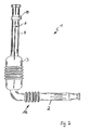
- Fig. 1 shows a filter pipe 1 for the intake manifold of an internal combustion engine with a Rohluftrohr 2, which opens to a filter housing 3, to which a clean air pipe 4 is connected. Air is sucked in through the connecting piece 15 of the unfiltered air tube 2 in the direction of the arrow 13, which air has to pass through a filter element accommodated in the filter housing 3 and thereby being freed from its dirty particle load. The combustion air that has passed through the filter element is supplied to the engine via the clean air tube 4 in the direction of arrow 14.
- the filter tube 1 is manufactured as a one-piece component by plastic extrusion.
- flexible sections are provided by blow molding during primary forming of the one-piece filter tube, in which the tube wall is formed as a bellows 12.
- the one-piece filter tube is easy to handle when installed in the intake manifold and is fitted via a connecting piece 15 on Rohluftrohr 2 and a port 16 on the clean air pipe 4 at the intended place in the intake manifold of the engine.
- By a suitable arrangement of the blow-molded bellows 12 can be done in a simple manner a tailor-made connection of the filter tube 1.
- the filter element has a larger cross-section than the tubes 2, 4 connected to the filter housing 3 and is thus fixed in its position.
- the filter tube 1 consists of a mixture of thermoplastic polypropylene (PP) and a thermoplastic elastomer (TPE) with over the length of the entire filter tube 1 partially different proportions.
- the proportions of the plastic mixture are about 90% thermoplastic elastomer (TPE) in the region of the clean air tube 4 up to 10% TPE in the region of the filter housing 3 and the Rohluftrohres 2 varies. Due to the high proportions of 90% to 10% TPE / PP, the clean air tube 4 is temporarily expandable in its cross section, whereby an introduction of the filter element with a larger cross-section than the tube cross-section is possible to the intended position.
- the rubber-elastic TPE After passing through the filter element, the rubber-elastic TPE retreats to the original normal position with reduced tube cross-section.
- the filter element In the area of the filter housing 3, that is to say at the point provided for the filter element, the filter element bears against the pipe wall and is axially held in its position by the following tapered section.
- fixation by gluing or by incorporation of a foam gasket may be useful.
- the unfiltered air tube 2 can be designed by an appropriate distribution of the material components over the length of the filter tube 1 with an expandable cross section.
- Fig. 2 shows an alternative embodiment of a one-piece filter tube 1, wherein the clean air tube 4 is provided with a reaching to the filter housing 3 longitudinal slot 6.
- the continuous longitudinal slot 6 allows unfolding of the clean air tube 4 and an insertion of the filter element in the filter housing 3 with a larger cross-section.
- the gap 6 is held together by a clean air tube 4 encompassing clamp 19 or a clip connection.
- a secure seal of the longitudinal slot 6 can be achieved by arranging a shrink tube.
- the unfiltered air pipe 2 may be provided with a longitudinal slot and the introduction of the filter element from the Rohluftseite done, which can be dispensed with a complete sealing of the longitudinal slot.
- Fig. 2a shows an alternative embodiment of a one-piece filter tube 1, in which instead of a bellows 12 in the tube design after Fig. 2 a flexible pipe section 20 is provided.
- the unfiltered air pipe 2 is designed to be flexible and can be pivoted to fit in a suction pipe in the direction of arrow 21.
- the pipe wall in the flexible section is designed to be flexible and the arc lengths of the pipe wall matched to the bent mounting position of the pipe according to the bending radius, so that in the straight position 2a of the Rohluftrohres the dotted line shown 22 results in the pipe wall to the greater length of the tube to record in this wall section.
- This design has compared to the execution of the flexible pipe section according to Fig. 2 with a bellows the advantage of lower pressure losses at the same cross sections over the pipe length.
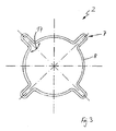
- Fig. 3 shows a cross section through an expandable tube, in the present case, the unfiltered tube 2 according to an alternative embodiment.
- the wall 8 of the Rohluftrohres is provided over the circumference of the Rohluftrohres 2 with radially outwardly drawn expansion creases 7.
- the legs of the expanding folds 7 are pushed apart in the direction of arrow 17 and the tube cross section is increased.
- Fig. 4 shows a further embodiment of a filter tube 1 with a filter housing 3 with one piece connected Rohluftrohr 2 and clean air tube 4 on the opposite sides of the filter housing 3.
- a cross-section Q elastically reducible filter cartridge fifth intended.
- a mounting tube not shown here is used, in which the folded filter cartridge 5 is added. The mounting tube is inserted into the unfiltered air tube 2 and pushed to the intended position in the filter housing 3. Thereafter, the filter cartridge 5 is pushed out of the mounting tube with a plunger and expands in the filter housing 3.
- a holding means can be used which holds the filter cartridge 5 in the reduced-volume form and is released into the filter housing 3 after insertion of the filter cartridge.
- a circumferential groove 9 is recessed in the region of the filter housing 3, in which after insertion of the filter cartridge 5, a seal 10 is injected from PUR foam.
- the filter element 5 is axially fixed and additionally precluded an unwanted flow around the filter element 5.
- the unfiltered air tube 2, the filter housing 3 and the clean air tube 4 are manufactured as a one-piece filter tube by injection molding.
- a bellows 18 may be provided by blow molding at the suitable pipe locations.
- an expandable tube may be expedient in addition to the filter cartridge 5 which can be reduced in cross-section.
Landscapes
- Engineering & Computer Science (AREA)
- Chemical & Material Sciences (AREA)
- Combustion & Propulsion (AREA)
- Mechanical Engineering (AREA)
- General Engineering & Computer Science (AREA)
- Chemical Kinetics & Catalysis (AREA)
- Filtering Of Dispersed Particles In Gases (AREA)
- Piezo-Electric Or Mechanical Vibrators, Or Delay Or Filter Circuits (AREA)
- Percussion Or Vibration Massage (AREA)
- Extrusion Moulding Of Plastics Or The Like (AREA)
- Control Of Motors That Do Not Use Commutators (AREA)
Claims (10)
- Conduite de filtre, en particulier pour le système collecteur d'admission d'un moteur à combustion avec un boîtier de filtre, avec un conduit d'air brut (2) qui débouche dans le boîtier de filtre (3) dans lequel est placé un élément filtrant (5), et avec un conduit d'air pur (4) raccordé au boîtier de filtre (3) pour évacuer l'air pur ayant traversé l'élément filtrant (5), caractérisée en ce que le conduit d'air pur (4), le boîtier de filtre (3) et le conduit d'air brut (2) forment un conduit de filtre (1) d'un seul tenant, l'un des conduits (2) raccordés au boîtier de filtre (3) présentant une section (Q) pouvant être temporairement élargie.
- Conduite de filtre selon la revendication 1, caractérisée en ce que le conduit extensible (2) est muni d'une fente longitudinale (6).
- Conduite de filtre selon la revendication 1, caractérisée en ce que le conduit extensible (2) est muni sur sa longueur, sur sa circonférence, d'au moins un pli d'écartement (7) dirigé radialement vers l'extérieur.
- Conduite de filtre selon la revendication 3, caractérisée en ce que plusieurs plis d'écartement (7) diamétralement opposés sont prévus.
- Conduite de filtre selon la revendication 1, caractérisée en ce que le conduit de filtre (1) est constitué, au niveau du conduit extensible (2), d'une matière synthétique élastique, en particulier d'un mélange d'un matériau thermoplastique et d'un matériau synthétique ou caoutchouc, avec des proportions variables par sections.
- Conduite de filtre selon la revendication 5, caractérisée par du polypropylène (PP) comme matériau thermoplastique.
- Conduite de filtre, en particulier pour le système collecteur d'admission d'un moteur à combustion avec un boîtier de filtre, avec un conduit d'air brut (2), qui débouche dans le boîtier de filtre (3) dans lequel est placé un élément filtrant (5), et avec un conduit d'air pur (4) raccordé au boîtier de filtre (3) pour évacuer l'air pur ayant traversé l'élément filtrant (5), caractérisée en ce que le conduit d'air brut (2), le boîtier de filtre (3) et le conduit d'air pur (4) forment un conduit de filtre (1) d'un seul tenant et en ce que, pour l'insertion dans le boîtier de filtre (3), il est possible de réduire élastiquement la section (Q) de l'élément filtrant (5).
- Conduite de filtre selon la revendication 7, caractérisée par un élément de maintien pour l'élément filtrant (5) réduit élastiquement, qui peut être détaché lors de l'introduction de l'élément filtrant (5) dans le conduit (2) dans la position prévue pour l'élément filtrant (5).
- Conduite de filtre selon la revendication 7, caractérisée par un conduit de montage pouvant être enfilé dans le conduit de filtre (1) et dans lequel l'élément filtrant (5) peut être placé.
- Conduite de filtre selon l'une des revendications précédentes, caractérisé en ce qu'entre l'élément filtrant (5) et une paroi (8) du conduit de filtre (1), un joint (10) en particulier constitué d'une mousse de matière synthétique et notamment de PUR, est inséré de préférence par injection dans une rainure périphérique (9) ménagée dans la paroi (8).
Priority Applications (1)
| Application Number | Priority Date | Filing Date | Title |
|---|---|---|---|
| PL06118934T PL1757798T3 (pl) | 2005-08-22 | 2006-08-15 | Filtracyjny przewód rurowy |
Applications Claiming Priority (1)
| Application Number | Priority Date | Filing Date | Title |
|---|---|---|---|
| DE202005013293U DE202005013293U1 (de) | 2005-08-22 | 2005-08-22 | Filterrohrleitung |
Publications (2)
| Publication Number | Publication Date |
|---|---|
| EP1757798A1 EP1757798A1 (fr) | 2007-02-28 |
| EP1757798B1 true EP1757798B1 (fr) | 2008-05-28 |
Family
ID=37336293
Family Applications (1)
| Application Number | Title | Priority Date | Filing Date |
|---|---|---|---|
| EP06118934A Not-in-force EP1757798B1 (fr) | 2005-08-22 | 2006-08-15 | Conduite pour élément filtrant |
Country Status (5)
| Country | Link |
|---|---|
| EP (1) | EP1757798B1 (fr) |
| AT (1) | ATE397155T1 (fr) |
| DE (2) | DE202005013293U1 (fr) |
| ES (1) | ES2307266T3 (fr) |
| PL (1) | PL1757798T3 (fr) |
Families Citing this family (1)
| Publication number | Priority date | Publication date | Assignee | Title |
|---|---|---|---|---|
| DE102011111366A1 (de) | 2011-08-29 | 2013-02-28 | Mann+Hummel Gmbh | Filterelement und Verfahren zu dessen Herstellung |
Family Cites Families (9)
| Publication number | Priority date | Publication date | Assignee | Title |
|---|---|---|---|---|
| US2915187A (en) * | 1956-02-06 | 1959-12-01 | Myron I Jaffe | Porous metal filter |
| US3519708A (en) * | 1966-11-21 | 1970-07-07 | Dow Chemical Co | Method of forming selectively permeable bodies from flexible polyurethane foam |
| DE6803429U (de) * | 1968-10-23 | 1969-07-10 | Filterwerk Mann & Hummel Gmbh | Ansaugrohr fuer luftfilter von brennkraftmaschinen |
| BE759678A (fr) * | 1969-12-01 | 1971-04-30 | Bosch Gmbh Robert | Dispositif de commande pour une installation d'injection de combustiblepour moteur a combustion interne a compression du melangeet a dispositif d'allumage commande de l'exterieur |
| US4523937A (en) * | 1982-09-29 | 1985-06-18 | Brubaker Thomas J | Model engine air filter |
| GB2239898B (en) * | 1990-01-10 | 1994-05-18 | Rover Group | Induction system for an internal combustion engine |
| JPH11132116A (ja) * | 1997-10-30 | 1999-05-18 | Denso Corp | 内燃機関の吸気装置 |
| DE10200100A1 (de) * | 2002-01-03 | 2003-08-14 | Mann & Hummel Filter | System zum Ansaugen von Luft für eine Brennkraftmaschine eines Nutzfahrzeugs |
| DE60300826T2 (de) * | 2002-01-25 | 2006-05-18 | Inoac Corp., Nagoya | Fluidfilter |
-
2005
- 2005-08-22 DE DE202005013293U patent/DE202005013293U1/de not_active Expired - Lifetime
-
2006
- 2006-08-15 EP EP06118934A patent/EP1757798B1/fr not_active Not-in-force
- 2006-08-15 AT AT06118934T patent/ATE397155T1/de not_active IP Right Cessation
- 2006-08-15 ES ES06118934T patent/ES2307266T3/es active Active
- 2006-08-15 PL PL06118934T patent/PL1757798T3/pl unknown
- 2006-08-15 DE DE502006000828T patent/DE502006000828D1/de active Active
Also Published As
| Publication number | Publication date |
|---|---|
| PL1757798T3 (pl) | 2008-11-28 |
| EP1757798A1 (fr) | 2007-02-28 |
| DE202005013293U1 (de) | 2006-12-28 |
| ES2307266T3 (es) | 2008-11-16 |
| DE502006000828D1 (de) | 2008-07-10 |
| ATE397155T1 (de) | 2008-06-15 |
Similar Documents
| Publication | Publication Date | Title |
|---|---|---|
| EP1987247A1 (fr) | Conduit tubulaire filtrant | |
| DE102007024287B4 (de) | Gas-Filtereinsatz und Gas-Filter enthaltend diesen | |
| EP1457247A1 (fr) | Filtre à air | |
| DE202008015440U1 (de) | Ansaugluftfilter für Verbrennungskraftmaschinen | |
| DE4118464A1 (de) | Verbindungsvorrichtung fuer den kuehlkreislauf von motoren | |
| EP1923115B1 (fr) | Installation de filtre | |
| WO2012062497A1 (fr) | Dispositif de fixation pour une ligne et procédé de fixation d'une ligne | |
| DE202009002178U1 (de) | Filtereinrichtung zur Filtration gasförmiger Fluide | |
| DE112015003624T5 (de) | Adaptives abdichtendes Luftansaugverbindungsstück | |
| EP2086662B1 (fr) | Dispositif de filtrage | |
| DE202006018187U1 (de) | Filtereinsatz | |
| EP1826393B1 (fr) | Système de filtration pour liquides | |
| DE102011009423B4 (de) | Montagehilfe für eine Belüftungsdüse und einen Belüftungskanal eines Kraftfahrzeuges, Belüftungsdüse, Belüftungskanal und Armaturentafel | |
| DE102012221555A1 (de) | Filteroberschale, Filter und Verfahren zum Herstellen einer Filteroberschale | |
| EP1757798B1 (fr) | Conduite pour élément filtrant | |
| DE102015122168A1 (de) | Lufttrocknerpatrone | |
| DE102011015238A1 (de) | Mehrteiliger Luftführungskanal | |
| WO2013023828A1 (fr) | Tubulure de raccordement pour tuyaux de filtre | |
| DE102019132361A1 (de) | Filtereinrichtung, insbesondere zur Gasfiltration | |
| DE202007011101U1 (de) | Filteranordnung | |
| DE102008015626A1 (de) | Verbindung einer Saugluftleitung mit einem Luftfiltergehäuse | |
| DE102018208508A1 (de) | Fluidverbindungsadapter, Fluidverbindungsanordnung sowie Verfahren zum Herstellen einer Fluidverbindungsanordnung | |
| DE102004024465A1 (de) | Ansaugsystem | |
| DE102004016051A1 (de) | Bremskraftverstärker | |
| DE102013007740A1 (de) | Filtereinrichtung |
Legal Events
| Date | Code | Title | Description |
|---|---|---|---|
| PUAI | Public reference made under article 153(3) epc to a published international application that has entered the european phase |
Free format text: ORIGINAL CODE: 0009012 |
|
| AK | Designated contracting states |
Kind code of ref document: A1 Designated state(s): AT BE BG CH CY CZ DE DK EE ES FI FR GB GR HU IE IS IT LI LT LU LV MC NL PL PT RO SE SI SK TR |
|
| AX | Request for extension of the european patent |
Extension state: AL BA HR MK YU |
|
| 17P | Request for examination filed |
Effective date: 20070315 |
|
| 17Q | First examination report despatched |
Effective date: 20070419 |
|
| AKX | Designation fees paid |
Designated state(s): AT BE BG CH CY CZ DE DK EE ES FI FR GB GR HU IE IS IT LI LT LU LV MC NL PL PT RO SE SI SK TR |
|
| GRAP | Despatch of communication of intention to grant a patent |
Free format text: ORIGINAL CODE: EPIDOSNIGR1 |
|
| GRAS | Grant fee paid |
Free format text: ORIGINAL CODE: EPIDOSNIGR3 |
|
| GRAA | (expected) grant |
Free format text: ORIGINAL CODE: 0009210 |
|
| AK | Designated contracting states |
Kind code of ref document: B1 Designated state(s): AT BE BG CH CY CZ DE DK EE ES FI FR GB GR HU IE IS IT LI LT LU LV MC NL PL PT RO SE SI SK TR |
|
| REG | Reference to a national code |
Ref country code: GB Ref legal event code: FG4D Free format text: NOT ENGLISH |
|
| REG | Reference to a national code |
Ref country code: CH Ref legal event code: EP |
|
| REF | Corresponds to: |
Ref document number: 502006000828 Country of ref document: DE Date of ref document: 20080710 Kind code of ref document: P |
|
| REG | Reference to a national code |
Ref country code: RO Ref legal event code: EPE |
|
| REG | Reference to a national code |
Ref country code: IE Ref legal event code: FG4D Free format text: LANGUAGE OF EP DOCUMENT: GERMAN |
|
| PG25 | Lapsed in a contracting state [announced via postgrant information from national office to epo] |
Ref country code: SI Free format text: LAPSE BECAUSE OF FAILURE TO SUBMIT A TRANSLATION OF THE DESCRIPTION OR TO PAY THE FEE WITHIN THE PRESCRIBED TIME-LIMIT Effective date: 20080528 |
|
| PG25 | Lapsed in a contracting state [announced via postgrant information from national office to epo] |
Ref country code: FI Free format text: LAPSE BECAUSE OF FAILURE TO SUBMIT A TRANSLATION OF THE DESCRIPTION OR TO PAY THE FEE WITHIN THE PRESCRIBED TIME-LIMIT Effective date: 20080528 |
|
| REG | Reference to a national code |
Ref country code: ES Ref legal event code: FG2A Ref document number: 2307266 Country of ref document: ES Kind code of ref document: T3 |
|
| PG25 | Lapsed in a contracting state [announced via postgrant information from national office to epo] |
Ref country code: LV Free format text: LAPSE BECAUSE OF FAILURE TO SUBMIT A TRANSLATION OF THE DESCRIPTION OR TO PAY THE FEE WITHIN THE PRESCRIBED TIME-LIMIT Effective date: 20080528 Ref country code: NL Free format text: LAPSE BECAUSE OF FAILURE TO SUBMIT A TRANSLATION OF THE DESCRIPTION OR TO PAY THE FEE WITHIN THE PRESCRIBED TIME-LIMIT Effective date: 20080528 |
|
| REG | Reference to a national code |
Ref country code: PL Ref legal event code: T3 |
|
| NLV1 | Nl: lapsed or annulled due to failure to fulfill the requirements of art. 29p and 29m of the patents act | ||
| PG25 | Lapsed in a contracting state [announced via postgrant information from national office to epo] |
Ref country code: IS Free format text: LAPSE BECAUSE OF FAILURE TO SUBMIT A TRANSLATION OF THE DESCRIPTION OR TO PAY THE FEE WITHIN THE PRESCRIBED TIME-LIMIT Effective date: 20080928 |
|
| REG | Reference to a national code |
Ref country code: IE Ref legal event code: FD4D |
|
| PG25 | Lapsed in a contracting state [announced via postgrant information from national office to epo] |
Ref country code: LT Free format text: LAPSE BECAUSE OF FAILURE TO SUBMIT A TRANSLATION OF THE DESCRIPTION OR TO PAY THE FEE WITHIN THE PRESCRIBED TIME-LIMIT Effective date: 20080528 Ref country code: DK Free format text: LAPSE BECAUSE OF FAILURE TO SUBMIT A TRANSLATION OF THE DESCRIPTION OR TO PAY THE FEE WITHIN THE PRESCRIBED TIME-LIMIT Effective date: 20080528 Ref country code: IE Free format text: LAPSE BECAUSE OF FAILURE TO SUBMIT A TRANSLATION OF THE DESCRIPTION OR TO PAY THE FEE WITHIN THE PRESCRIBED TIME-LIMIT Effective date: 20080528 Ref country code: SE Free format text: LAPSE BECAUSE OF FAILURE TO SUBMIT A TRANSLATION OF THE DESCRIPTION OR TO PAY THE FEE WITHIN THE PRESCRIBED TIME-LIMIT Effective date: 20080828 |
|
| PG25 | Lapsed in a contracting state [announced via postgrant information from national office to epo] |
Ref country code: SK Free format text: LAPSE BECAUSE OF FAILURE TO SUBMIT A TRANSLATION OF THE DESCRIPTION OR TO PAY THE FEE WITHIN THE PRESCRIBED TIME-LIMIT Effective date: 20080528 Ref country code: PT Free format text: LAPSE BECAUSE OF FAILURE TO SUBMIT A TRANSLATION OF THE DESCRIPTION OR TO PAY THE FEE WITHIN THE PRESCRIBED TIME-LIMIT Effective date: 20081028 |
|
| PG25 | Lapsed in a contracting state [announced via postgrant information from national office to epo] |
Ref country code: MC Free format text: LAPSE BECAUSE OF NON-PAYMENT OF DUE FEES Effective date: 20080831 |
|
| PLBE | No opposition filed within time limit |
Free format text: ORIGINAL CODE: 0009261 |
|
| STAA | Information on the status of an ep patent application or granted ep patent |
Free format text: STATUS: NO OPPOSITION FILED WITHIN TIME LIMIT |
|
| PG25 | Lapsed in a contracting state [announced via postgrant information from national office to epo] |
Ref country code: EE Free format text: LAPSE BECAUSE OF FAILURE TO SUBMIT A TRANSLATION OF THE DESCRIPTION OR TO PAY THE FEE WITHIN THE PRESCRIBED TIME-LIMIT Effective date: 20080528 Ref country code: BG Free format text: LAPSE BECAUSE OF FAILURE TO SUBMIT A TRANSLATION OF THE DESCRIPTION OR TO PAY THE FEE WITHIN THE PRESCRIBED TIME-LIMIT Effective date: 20080828 |
|
| 26N | No opposition filed |
Effective date: 20090303 |
|
| PG25 | Lapsed in a contracting state [announced via postgrant information from national office to epo] |
Ref country code: BE Free format text: LAPSE BECAUSE OF NON-PAYMENT OF DUE FEES Effective date: 20080831 |
|
| PG25 | Lapsed in a contracting state [announced via postgrant information from national office to epo] |
Ref country code: IT Free format text: LAPSE BECAUSE OF FAILURE TO SUBMIT A TRANSLATION OF THE DESCRIPTION OR TO PAY THE FEE WITHIN THE PRESCRIBED TIME-LIMIT Effective date: 20080528 |
|
| PG25 | Lapsed in a contracting state [announced via postgrant information from national office to epo] |
Ref country code: AT Free format text: LAPSE BECAUSE OF NON-PAYMENT OF DUE FEES Effective date: 20080815 |
|
| PG25 | Lapsed in a contracting state [announced via postgrant information from national office to epo] |
Ref country code: CY Free format text: LAPSE BECAUSE OF FAILURE TO SUBMIT A TRANSLATION OF THE DESCRIPTION OR TO PAY THE FEE WITHIN THE PRESCRIBED TIME-LIMIT Effective date: 20080528 Ref country code: HU Free format text: LAPSE BECAUSE OF FAILURE TO SUBMIT A TRANSLATION OF THE DESCRIPTION OR TO PAY THE FEE WITHIN THE PRESCRIBED TIME-LIMIT Effective date: 20081129 Ref country code: LU Free format text: LAPSE BECAUSE OF NON-PAYMENT OF DUE FEES Effective date: 20080815 |
|
| PG25 | Lapsed in a contracting state [announced via postgrant information from national office to epo] |
Ref country code: TR Free format text: LAPSE BECAUSE OF FAILURE TO SUBMIT A TRANSLATION OF THE DESCRIPTION OR TO PAY THE FEE WITHIN THE PRESCRIBED TIME-LIMIT Effective date: 20080528 |
|
| PG25 | Lapsed in a contracting state [announced via postgrant information from national office to epo] |
Ref country code: GR Free format text: LAPSE BECAUSE OF FAILURE TO SUBMIT A TRANSLATION OF THE DESCRIPTION OR TO PAY THE FEE WITHIN THE PRESCRIBED TIME-LIMIT Effective date: 20080829 |
|
| REG | Reference to a national code |
Ref country code: CH Ref legal event code: PL |
|
| GBPC | Gb: european patent ceased through non-payment of renewal fee |
Effective date: 20100815 |
|
| PG25 | Lapsed in a contracting state [announced via postgrant information from national office to epo] |
Ref country code: LI Free format text: LAPSE BECAUSE OF NON-PAYMENT OF DUE FEES Effective date: 20100831 Ref country code: CH Free format text: LAPSE BECAUSE OF NON-PAYMENT OF DUE FEES Effective date: 20100831 |
|
| PG25 | Lapsed in a contracting state [announced via postgrant information from national office to epo] |
Ref country code: GB Free format text: LAPSE BECAUSE OF NON-PAYMENT OF DUE FEES Effective date: 20100815 |
|
| PGFP | Annual fee paid to national office [announced via postgrant information from national office to epo] |
Ref country code: CZ Payment date: 20110809 Year of fee payment: 6 |
|
| PGFP | Annual fee paid to national office [announced via postgrant information from national office to epo] |
Ref country code: RO Payment date: 20120731 Year of fee payment: 7 |
|
| PGFP | Annual fee paid to national office [announced via postgrant information from national office to epo] |
Ref country code: PL Payment date: 20120824 Year of fee payment: 7 |
|
| PG25 | Lapsed in a contracting state [announced via postgrant information from national office to epo] |
Ref country code: CZ Free format text: LAPSE BECAUSE OF NON-PAYMENT OF DUE FEES Effective date: 20130815 Ref country code: RO Free format text: LAPSE BECAUSE OF NON-PAYMENT OF DUE FEES Effective date: 20130815 |
|
| PG25 | Lapsed in a contracting state [announced via postgrant information from national office to epo] |
Ref country code: PL Free format text: LAPSE BECAUSE OF NON-PAYMENT OF DUE FEES Effective date: 20130815 |
|
| REG | Reference to a national code |
Ref country code: PL Ref legal event code: LAPE |
|
| REG | Reference to a national code |
Ref country code: FR Ref legal event code: PLFP Year of fee payment: 11 |
|
| REG | Reference to a national code |
Ref country code: FR Ref legal event code: PLFP Year of fee payment: 12 |
|
| REG | Reference to a national code |
Ref country code: DE Ref legal event code: R081 Ref document number: 502006000828 Country of ref document: DE Owner name: MANN+HUMMEL GMBH, DE Free format text: FORMER OWNER: MANN + HUMMEL GMBH, 71638 LUDWIGSBURG, DE |
|
| REG | Reference to a national code |
Ref country code: FR Ref legal event code: PLFP Year of fee payment: 13 |
|
| PGFP | Annual fee paid to national office [announced via postgrant information from national office to epo] |
Ref country code: FR Payment date: 20190822 Year of fee payment: 14 Ref country code: DE Payment date: 20190822 Year of fee payment: 14 Ref country code: ES Payment date: 20190923 Year of fee payment: 14 |
|
| REG | Reference to a national code |
Ref country code: DE Ref legal event code: R119 Ref document number: 502006000828 Country of ref document: DE |
|
| PG25 | Lapsed in a contracting state [announced via postgrant information from national office to epo] |
Ref country code: DE Free format text: LAPSE BECAUSE OF NON-PAYMENT OF DUE FEES Effective date: 20210302 Ref country code: FR Free format text: LAPSE BECAUSE OF NON-PAYMENT OF DUE FEES Effective date: 20200831 |
|
| REG | Reference to a national code |
Ref country code: ES Ref legal event code: FD2A Effective date: 20220110 |
|
| PG25 | Lapsed in a contracting state [announced via postgrant information from national office to epo] |
Ref country code: ES Free format text: LAPSE BECAUSE OF NON-PAYMENT OF DUE FEES Effective date: 20200816 |