EP1757811B1 - Disque d'attachement pour une machine à piston hydrostatique et méthode de fabrication de ce disque - Google Patents
Disque d'attachement pour une machine à piston hydrostatique et méthode de fabrication de ce disque Download PDFInfo
- Publication number
- EP1757811B1 EP1757811B1 EP06023672A EP06023672A EP1757811B1 EP 1757811 B1 EP1757811 B1 EP 1757811B1 EP 06023672 A EP06023672 A EP 06023672A EP 06023672 A EP06023672 A EP 06023672A EP 1757811 B1 EP1757811 B1 EP 1757811B1
- Authority
- EP
- European Patent Office
- Prior art keywords
- connecting plate
- extruded profile
- plate
- connection plate
- produced
- Prior art date
- Legal status (The legal status is an assumption and is not a legal conclusion. Google has not performed a legal analysis and makes no representation as to the accuracy of the status listed.)
- Expired - Lifetime
Links
- 230000002706 hydrostatic effect Effects 0.000 title claims description 10
- 238000004519 manufacturing process Methods 0.000 title description 16
- XEEYBQQBJWHFJM-UHFFFAOYSA-N Iron Chemical compound [Fe] XEEYBQQBJWHFJM-UHFFFAOYSA-N 0.000 claims description 6
- 238000000034 method Methods 0.000 claims description 5
- RYGMFSIKBFXOCR-UHFFFAOYSA-N Copper Chemical compound [Cu] RYGMFSIKBFXOCR-UHFFFAOYSA-N 0.000 claims description 3
- 239000000956 alloy Substances 0.000 claims description 3
- 229910045601 alloy Inorganic materials 0.000 claims description 3
- 229910052782 aluminium Inorganic materials 0.000 claims description 3
- XAGFODPZIPBFFR-UHFFFAOYSA-N aluminium Chemical compound [Al] XAGFODPZIPBFFR-UHFFFAOYSA-N 0.000 claims description 3
- 238000009749 continuous casting Methods 0.000 claims description 3
- 229910052802 copper Inorganic materials 0.000 claims description 3
- 239000010949 copper Substances 0.000 claims description 3
- 229910052742 iron Inorganic materials 0.000 claims description 3
- 238000005520 cutting process Methods 0.000 claims description 2
- 238000005553 drilling Methods 0.000 claims description 2
- 238000003698 laser cutting Methods 0.000 claims description 2
- 229910052751 metal Inorganic materials 0.000 claims description 2
- 239000002184 metal Substances 0.000 claims description 2
- 150000002739 metals Chemical class 0.000 claims description 2
- XLYOFNOQVPJJNP-UHFFFAOYSA-N water Substances O XLYOFNOQVPJJNP-UHFFFAOYSA-N 0.000 claims description 2
- 239000004411 aluminium Substances 0.000 claims 1
- 239000000470 constituent Substances 0.000 claims 1
- 238000001816 cooling Methods 0.000 description 5
- 239000012530 fluid Substances 0.000 description 4
- 239000000463 material Substances 0.000 description 3
- 238000005266 casting Methods 0.000 description 2
- 230000006835 compression Effects 0.000 description 2
- 238000007906 compression Methods 0.000 description 2
- 238000006073 displacement reaction Methods 0.000 description 2
- 238000003825 pressing Methods 0.000 description 2
- 238000010276 construction Methods 0.000 description 1
- 230000001419 dependent effect Effects 0.000 description 1
- 238000011161 development Methods 0.000 description 1
- 230000018109 developmental process Effects 0.000 description 1
- 239000011265 semifinished product Substances 0.000 description 1
- 238000000926 separation method Methods 0.000 description 1
- 238000007493 shaping process Methods 0.000 description 1
- 230000007704 transition Effects 0.000 description 1
Images

Classifications
-
- B—PERFORMING OPERATIONS; TRANSPORTING
- B23—MACHINE TOOLS; METAL-WORKING NOT OTHERWISE PROVIDED FOR
- B23P—METAL-WORKING NOT OTHERWISE PROVIDED FOR; COMBINED OPERATIONS; UNIVERSAL MACHINE TOOLS
- B23P13/00—Making metal objects by operations essentially involving machining but not covered by a single other subclass
- B23P13/04—Making metal objects by operations essentially involving machining but not covered by a single other subclass involving slicing of profiled material
-
- B—PERFORMING OPERATIONS; TRANSPORTING
- B22—CASTING; POWDER METALLURGY
- B22D—CASTING OF METALS; CASTING OF OTHER SUBSTANCES BY THE SAME PROCESSES OR DEVICES
- B22D11/00—Continuous casting of metals, i.e. casting in indefinite lengths
- B22D11/009—Continuous casting of metals, i.e. casting in indefinite lengths of work of special cross-section, e.g. I-beams, U-profiles
-
- F—MECHANICAL ENGINEERING; LIGHTING; HEATING; WEAPONS; BLASTING
- F04—POSITIVE - DISPLACEMENT MACHINES FOR LIQUIDS; PUMPS FOR LIQUIDS OR ELASTIC FLUIDS
- F04B—POSITIVE-DISPLACEMENT MACHINES FOR LIQUIDS; PUMPS
- F04B1/00—Multi-cylinder machines or pumps characterised by number or arrangement of cylinders
- F04B1/12—Multi-cylinder machines or pumps characterised by number or arrangement of cylinders having cylinder axes coaxial with, or parallel or inclined to, main shaft axis
- F04B1/14—Multi-cylinder machines or pumps characterised by number or arrangement of cylinders having cylinder axes coaxial with, or parallel or inclined to, main shaft axis having stationary cylinders
- F04B1/141—Details or component parts
- F04B1/145—Housings
-
- F—MECHANICAL ENGINEERING; LIGHTING; HEATING; WEAPONS; BLASTING
- F04—POSITIVE - DISPLACEMENT MACHINES FOR LIQUIDS; PUMPS FOR LIQUIDS OR ELASTIC FLUIDS
- F04B—POSITIVE-DISPLACEMENT MACHINES FOR LIQUIDS; PUMPS
- F04B1/00—Multi-cylinder machines or pumps characterised by number or arrangement of cylinders
- F04B1/12—Multi-cylinder machines or pumps characterised by number or arrangement of cylinders having cylinder axes coaxial with, or parallel or inclined to, main shaft axis
- F04B1/20—Multi-cylinder machines or pumps characterised by number or arrangement of cylinders having cylinder axes coaxial with, or parallel or inclined to, main shaft axis having rotary cylinder block
- F04B1/2014—Details or component parts
- F04B1/2064—Housings
-
- F—MECHANICAL ENGINEERING; LIGHTING; HEATING; WEAPONS; BLASTING
- F04—POSITIVE - DISPLACEMENT MACHINES FOR LIQUIDS; PUMPS FOR LIQUIDS OR ELASTIC FLUIDS
- F04B—POSITIVE-DISPLACEMENT MACHINES FOR LIQUIDS; PUMPS
- F04B53/00—Component parts, details or accessories not provided for in, or of interest apart from, groups F04B1/00 - F04B23/00 or F04B39/00 - F04B47/00
- F04B53/007—Cylinder heads
-
- F—MECHANICAL ENGINEERING; LIGHTING; HEATING; WEAPONS; BLASTING
- F04—POSITIVE - DISPLACEMENT MACHINES FOR LIQUIDS; PUMPS FOR LIQUIDS OR ELASTIC FLUIDS
- F04B—POSITIVE-DISPLACEMENT MACHINES FOR LIQUIDS; PUMPS
- F04B53/00—Component parts, details or accessories not provided for in, or of interest apart from, groups F04B1/00 - F04B23/00 or F04B39/00 - F04B47/00
- F04B53/16—Casings; Cylinders; Cylinder liners or heads; Fluid connections
-
- Y—GENERAL TAGGING OF NEW TECHNOLOGICAL DEVELOPMENTS; GENERAL TAGGING OF CROSS-SECTIONAL TECHNOLOGIES SPANNING OVER SEVERAL SECTIONS OF THE IPC; TECHNICAL SUBJECTS COVERED BY FORMER USPC CROSS-REFERENCE ART COLLECTIONS [XRACs] AND DIGESTS
- Y10—TECHNICAL SUBJECTS COVERED BY FORMER USPC
- Y10T—TECHNICAL SUBJECTS COVERED BY FORMER US CLASSIFICATION
- Y10T29/00—Metal working
- Y10T29/49—Method of mechanical manufacture
- Y10T29/49229—Prime mover or fluid pump making
- Y10T29/49236—Fluid pump or compressor making
Definitions
- the invention relates to the connection plate of a hydrostatic machine, in particular an axial piston machine.
- connection plate in an axial piston machine in bent axis design.
- the connection plate closes an elliptical housing section.
- a formed as a biconvex control lens molded control body is slidably disposed in a circular path-shaped support and pivot bearing in the connection plate.
- the control body has openings for the passage of hydraulic medium.
- connection plates are made of individual slab-cast or forged blanks.
- connection plate can only be changed by high costs in the manufacturing process, for example by a new mold or a new die.
- connection plate which can be manufactured inexpensively and with little effort.
- the terminal plate blank formed as an intermediate step for manufacturing the terminal plate is cut from an extruded profile and not individually cast or forged as in conventional manufacturing processes.
- the extruded profile can be made particularly simple and inexpensive.
- the extruded profile consists at least partially of aluminum, copper or iron or of an alloy with at least one of these metals.
- the connection plate can thereby be easily manufactured with the desired material properties.
- the extruded profile covers in cross-section with the contour of the finished connection plate.
- the cut from the extruded connection plate blank must then not be reworked in its contour.
- the extruded profile is cut to at least two terminal board blanks.
- the manufacturing process is much easier, since a plurality of terminal plate blanks can be produced in a simple manner from an extruded profile.
- connection plate according to the invention and the inventive method for producing the connection plate on the basis of FIGS. 2 and 3 will be described using the Fig. 1 a hydrostatic machine with a connection plate according to the prior art for a better understanding of the invention explained.
- the in the Fig. 1 shown axial piston machine is designed in swash plate design with adjustable displacement volume and a current direction and includes in a known manner as essential components a hollow cylindrical housing 1 with a frontally open end (upper end in FIG. 1 ), a housing 1 attached to the open end closing terminal plate 2, a lifting or swash plate 3, a control body 4, a drive shaft 5, a cylinder drum 6 and in the illustrated embodiment, an optional cooling circuit 7.1.
- the swash plate 3 is formed as a so-called pivoting cradle with a semi-cylindrical cross-section and is supported by two spaced parallel to the pivot direction bearing surfaces under hydrostatic discharge to two correspondingly shaped bearing shells 8, attached to the inner surface of the terminal plate 2 opposite housing end wall 9 are.
- the hydrostatic discharge takes place in a known manner via pressure pockets 10 which are formed in the bearing shells 8 and are supplied via connections 11 with pressure medium.
- Actuator 13 engages over an extending in the direction of the terminal plate 2 arm 14 on the swash plate 3 and serves to pivot the same about a pivot axis perpendicular to the pivot axis.
- the control body 4 is fixed to the housing interior facing the inner surface of the connection plate 2 and provided with two through openings 15 in the form of kidney-shaped control slots, which via a pressure channel 16D and suction channel 16S in the connection plate 2 to a pressure and suction line, not shown are connected.
- the pressure channel 16D has a smaller flow area than the suction channel 16S.
- the housing interior facing and spherically formed control surface of the control body 4 serves as a bearing surface for the cylinder drum. 6
- the drive shaft 5 protrudes through a through hole in the housing end wall 9 in the housing 1 and is by means of a bearing 17 in this through hole and by means of another bearing 18 in a narrower bore portion of an end extended blind bore 19 in the terminal plate 2 and one of these narrower bore portion adjacent region of a central through hole 20 in the control body 4 rotatably mounted.
- the drive shaft 5 passes through in the interior of the housing 1 further has a central through hole 21 in the swash plate 3, whose diameter is dimensioned according to the largest swing deflection of the swash plate 3, and a central through hole in the cylinder drum 6 with two bore sections.
- One of these bore sections is integrally formed on the cylinder drum 6, via the Swash plate 3 facing end face 22 protruding sleeve-shaped extension 23 is formed, via which the cylinder drum 6 by means of a splined connection 24 rotatably connected to the drive shaft 5 is connected.
- the remaining bore portion is formed with a conical shape. It tapers from its cross section of largest diameter near the first bore section to its cross section of smallest diameter near the control body 4 adjacent end face or bearing surface of the cylinder drum 6.
- the defined by the drive shaft 5 and this conical bore portion annular space is denoted by the reference numeral 25th designated.
- the cylinder drum 6 has generally axially extending, stepped cylinder bores 26 which are arranged uniformly on a coaxial to the drive shaft axis pitch circle.
- the cylinder bores 26 open on the cylinder drum end face 22 directly and on the cylinder body bearing surface facing the control body 4 via mouth channels 27 on the same pitch circle as the control slots.
- a bushing 28 is used in each of the cylinder drum end face 22 directly opening cylinder bore portions of larger diameter a bushing 28 is used.
- the cylinder bores 26 including the liners 28 are referred to herein as cylinders.
- piston 29 are provided at their swash plate 3 facing the ends with ball heads 30 which are mounted in sliding blocks 31 and are hydrostatically mounted on this attached to the swash plate 3 annular sliding disk 32.
- Each slide shoe 31 is provided on its sliding surface 32 facing sliding surface, each with a pressure pocket, not shown, which has a Through hole 33 in the shoe 31 is connected to a stepped axial passage 34 in the piston 29 and connected in this way with the delimited by the piston 29 in the cylinder bore 26 working space of the cylinder.
- a throttle is formed in the region of the associated ball head 30.
- An axially displaceable means of the spline connection 24 arranged on the drive shaft 5 and acted upon by a spring 35 in the direction of the swash plate 3 hold-down device 36 holds the sliding blocks 31 in abutment against the sliding disk 32nd
- the space not occupied in the housing interior by the components 3 to 6 accommodated therein serves as a leakage space 37 which, during operation of the axial piston machine, passes through all gaps, such as between the cylinders and the pistons 29, the control body 4 and the cylinder drum 6, the swash plate 3 and the sliding disk 32 and the bearing shells 8, etc., absorbs leaking leakage fluid.
- the axial piston machine is intended for operation with oil as a fluid.
- the cylinder drum 6 is rotated together with the piston 29 in rotation.
- the swashplate 3 is pivoted into an inclined position relative to the cylinder drum 6 by actuation of the adjusting device 13, all pistons 29 perform lifting movements.
- each piston 29 passes through a suction and a Compression stroke, with corresponding oil flows are generated, the supply and discharge via the orifice channels 27, the control slots 15 and the pressure and suction channel 16 D, 16 S done.
- each piston 29 pressure oil from the cylinder in question via the axial passage 34 and the through hole 33 in the associated shoe 31 in the pressure pocket and builds a pressure field between the sliding disk 32 and the respective shoe 31, as a hydrostatic bearing for the latter serves. Furthermore, pressurized oil is fed via the connections 11 to the pressure pockets 10 in the bearing shells 8 for the hydrostatic support of the swashplate 3.
- necessary cooling circuit 7.1 is connected to the leakage chamber 37 and includes the conical annular space 25 (so-called leakage fluid receiving space), the through hole 20 in the control body 4, the blind bore 19 (so-called further leakage fluid -Avem fortuneraum), a connecting this with the leakage chamber 37 connecting line 38, which opens into a circumferential groove 39 in the inner surface of the connection plate 2, and the cylinders 26, 28 circumferentially associated cooling regions which are connected via inlet channels 40 to the conical annular space 25 and via drain channels 41 on the cylindrical boundary surface 42 of the cylinder drum 6 open into the leakage chamber 37. All inlet channels 40 open into the conical annular space 25 at its cross section of the largest diameter and, like all drainage channels 41, extend essentially radially through the cylinder drum 6.
- Each cylinder is associated with a cooling area in the form of an annular space 43, which is formed as a circumferential groove in the wall of the cylinder bore portion of larger diameter and covered by the bushing 28.
- the annular space 43 extends from near the mouth region of the cylinder bore 26 over approximately two-thirds of the length thereof in the direction of the mouth channels 27 and thus represents a top cooling zone associated with the upper dead center position of the piston 29.
- An inflow channel 40 and an outlet channel 41 all open approximately in the middle in the annular space 43 and extend coaxially to each other.
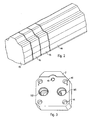
- Fig. 2 shows an extruded profile 44 from which the first three terminal plate blanks 45 are cut to length in an inventive method step.
- the extruded profile has a cross section that is the same throughout along its longitudinal axis and is shaped according to the desired contour of the finished connection plate 2.
- complex subsequent processing steps for shaping the contour of the connection plate 2 can be omitted.
- the extruded profile 44 is cut to several connection plate blanks 45 of the same or different thickness or thickness. This makes it very easy to make connection plate blanks 45 for the production of connection plates 2 for different types of hydrostatic machines, especially for pumps of different performance.
- connection plate blanks 45 are separated from the extruded profile 44, for example by sawing or water jet cutting. Depending on the material of the extruded profile 44, the necessary accuracy and the desired quantities of the connection plates 2, other separation methods can be used, for example laser cutting or a burn-out.
- the terminal plate blanks 45 are separated at right angles to the longitudinal axis of the extruded profile 44, so that the two perpendicular to the longitudinal axis of the connection plate blanks 45 lying surfaces parallel.
- the connection plate blanks 45 can also be separated or cut to length from the extruded profile 44 by an oblique cut, whereby the connection plate blank 45 or the connection plate 2 is wedge-shaped or concave.
- the extruded profile 44 is preferably at least partially made of aluminum, iron or copper or a corresponding alloy.
- the extruded profile 44 is produced for example by casting or pressing.
- the extruded profile 44 is thus designed or manufactured, for example, as a continuous casting profile 44 or as an extruded profile 44.
- Fig. 3 shows an exemplary embodiment of a connection plate according to the invention 2.
- the connection plate 2 has been cut in a method step according to the invention first of the extruded profile 44 with a perpendicular to the longitudinal axis of the extruded profile 44 extending section of the extruded profile 44.
- the resulting connection plate blank 45 is further processed Service.
- the pressure channel 16D, the suction channel 16S and several other openings 46 which may be part of a screw, for example, introduced by drilling in the terminal plate blank 45.
- the connection line 38, the blind bore 19 and the channel 39 can be introduced into the connection plate blank 45.
- connection plate 2 produced by the method according to the invention can be produced very inexpensively and quickly in various thicknesses or thicknesses, so that there are great cost advantages over the manufacturing process known from the prior art.
Landscapes
- Engineering & Computer Science (AREA)
- Mechanical Engineering (AREA)
- General Engineering & Computer Science (AREA)
- Reciprocating Pumps (AREA)
Claims (4)
- Plaque de raccordement (1) d'une machine hydrostatique, la plaque de raccordement (2) étant fabriquée à partir d'un profilé extrudé (44) et la plaque de raccordement (2) étant fabriquée à partir d'une ébauche de plaque de raccordement (45) qui est séparée du profilé extrudé (44), le contour du profilé extrudé (44) et le contour de la plaque de raccordement (2) se recouvrant en section et, dans la plaque de raccordement (2), étant incorporés un alésage borgne (19) et une gorge (39) et/ou un conducteur de raccordement (38),
caractérisée en ce que
dans la plaque de raccordement (1), sont incorporées par perçage plusieurs autres ouvertures (46) en tant que partie composante d'un assemblage vissé. - Plaque de raccordement selon la revendication 1,
caractérisée en ce que
la plaque de raccordement (2) est fabriquée à partir d'un profilé extrudé (44) qui est fabriqué par moulage ou pressage. - Plaque de raccordement selon la revendication 1 ou la revendication 2,
caractérisée en ce que
la plaque de raccordement (2) est fabriquée à partir d'un profilé extrudé (44) qui constate au moins partiellement en aluminium, en fer ou en cuivre ou en un alliage comportant au moine l'un de ces métaux. - Plaque de raccordement selon l'une des revendications 1 à 3,
caractérisée en ce que
une ébauche de plaque de raccordement (45) à partir de laquelle est fabriquée la plaque de raccordement (2) est séparée par sillage, découpe au laser, découpe au jet d'eau ou par un procédé de flambage du profilé extrudé (44).
Applications Claiming Priority (2)
| Application Number | Priority Date | Filing Date | Title |
|---|---|---|---|
| DE10349318A DE10349318B4 (de) | 2003-10-23 | 2003-10-23 | Anschlußplatte einer hydrostatischen Maschine und Verfahren zur Herstellung der Anschlußplatte |
| EP04765920A EP1682777B1 (fr) | 2003-10-23 | 2004-10-11 | Procede de production d'une plaque de raccordement d'une machine hydrostatique |
Related Parent Applications (1)
| Application Number | Title | Priority Date | Filing Date |
|---|---|---|---|
| EP04765920A Division EP1682777B1 (fr) | 2003-10-23 | 2004-10-11 | Procede de production d'une plaque de raccordement d'une machine hydrostatique |
Publications (2)
| Publication Number | Publication Date |
|---|---|
| EP1757811A1 EP1757811A1 (fr) | 2007-02-28 |
| EP1757811B1 true EP1757811B1 (fr) | 2008-07-16 |
Family
ID=34484940
Family Applications (2)
| Application Number | Title | Priority Date | Filing Date |
|---|---|---|---|
| EP06023672A Expired - Lifetime EP1757811B1 (fr) | 2003-10-23 | 2004-10-11 | Disque d'attachement pour une machine à piston hydrostatique et méthode de fabrication de ce disque |
| EP04765920A Expired - Lifetime EP1682777B1 (fr) | 2003-10-23 | 2004-10-11 | Procede de production d'une plaque de raccordement d'une machine hydrostatique |
Family Applications After (1)
| Application Number | Title | Priority Date | Filing Date |
|---|---|---|---|
| EP04765920A Expired - Lifetime EP1682777B1 (fr) | 2003-10-23 | 2004-10-11 | Procede de production d'une plaque de raccordement d'une machine hydrostatique |
Country Status (4)
| Country | Link |
|---|---|
| US (1) | US20090013864A1 (fr) |
| EP (2) | EP1757811B1 (fr) |
| DE (3) | DE10349318B4 (fr) |
| WO (1) | WO2005042975A1 (fr) |
Families Citing this family (12)
| Publication number | Priority date | Publication date | Assignee | Title |
|---|---|---|---|---|
| DE102006003259A1 (de) | 2006-01-19 | 2007-07-26 | Behr Thermot-Tronik Gmbh | Verfahren zum Herstellen von Ventilgehäusen und Ventilgehäuse |
| DE102006004383A1 (de) * | 2006-01-31 | 2007-08-02 | BSH Bosch und Siemens Hausgeräte GmbH | Hocheinbau-Gargerät |
| DE102010013008A1 (de) | 2009-04-09 | 2010-10-14 | Robert Bosch Gmbh | Hydraulische Axialkolbenmaschine mit einer Anschlussplatte |
| DE102009026417A1 (de) * | 2009-05-22 | 2010-12-02 | Robert Bosch Gmbh | Pumpengehäuse eines Kraftfahrzeug-Hydroaggregats |
| DE102010048073A1 (de) * | 2010-04-16 | 2011-10-20 | Robert Bosch Gmbh | Maschinengehäuse einer Hydromaschine |
| DE102010062270A1 (de) * | 2010-12-01 | 2012-06-06 | Robert Bosch Gmbh | Blockförmiges Pumpengehäuse einer Fahrzeugbremsanlage und Verfahren zu dessen Herstellung |
| DE102012221135A1 (de) * | 2012-11-20 | 2014-05-22 | Robert Bosch Gmbh | Verfahren zum Herstellen einer Ventileinrichtung sowie entsprechende Ventileinrichtung |
| DE102014217143A1 (de) * | 2014-08-28 | 2016-03-03 | Robert Bosch Gmbh | Zylindertrommel für eine hydrostatische Axialkolbeneinheit |
| US20200232450A9 (en) * | 2015-09-29 | 2020-07-23 | Kerr Machine Co. | Multi-Piece Fluid End |
| DE102018205884A1 (de) * | 2018-04-18 | 2019-10-24 | Robert Bosch Gmbh | Axialkolbenmaschine mit Druckentlastung in den Durchtriebsraum |
| CN110315283B (zh) * | 2019-05-09 | 2021-09-24 | 泰州市创新电子有限公司 | 一体挤铝式铝支架生产方法 |
| CN115351108A (zh) * | 2022-08-30 | 2022-11-18 | 广东威灵电机制造有限公司 | 热管理集成模块的阀座的加工方法 |
Family Cites Families (9)
| Publication number | Priority date | Publication date | Assignee | Title |
|---|---|---|---|---|
| US4782738A (en) * | 1985-09-18 | 1988-11-08 | Gast Manufacturing Corporation | Compressor with adjustable head clearance |
| US4978284A (en) * | 1990-03-01 | 1990-12-18 | Cook James E | Double acting simplex plunger pump |
| US5173039A (en) * | 1991-09-27 | 1992-12-22 | Cook James E | Double acting simplex plunger pump |
| DE4423023C2 (de) * | 1994-06-30 | 1998-07-09 | Brueninghaus Hydromatik Gmbh | Axialkolbenmaschine mit einem Kühlkreislauf für die Zylinder und Kolben |
| DE29614204U1 (de) * | 1996-08-16 | 1996-10-02 | Kuhnke GmbH, 23714 Malente | Ventilgehäuse |
| DE19643389C1 (de) * | 1996-10-21 | 1998-01-02 | Brueninghaus Hydromatik Gmbh | Axialkolbenmaschine mit variabler Fixierung der Steuerscheibe |
| DE19914268C2 (de) * | 1999-03-29 | 2002-02-28 | Brueninghaus Hydromatik Gmbh | Axialkolbenmaschine und Steuerkörper für eine Axialkolbenmaschine |
| DE102004043897A1 (de) * | 2004-03-09 | 2005-09-29 | Brueninghaus Hydromatik Gmbh | Antriebssystem mit gemeinsamen Steuerdruckanschluss |
| DE102006021570A1 (de) * | 2006-04-10 | 2007-10-18 | Robert Bosch Gmbh | Hydrostatische Kolbenmaschine mit drehbarer Steuerscheibe |
-
2003
- 2003-10-23 DE DE10349318A patent/DE10349318B4/de not_active Expired - Fee Related
-
2004
- 2004-10-11 EP EP06023672A patent/EP1757811B1/fr not_active Expired - Lifetime
- 2004-10-11 WO PCT/EP2004/011350 patent/WO2005042975A1/fr not_active Ceased
- 2004-10-11 DE DE502004007640T patent/DE502004007640D1/de not_active Expired - Lifetime
- 2004-10-11 US US10/577,001 patent/US20090013864A1/en not_active Abandoned
- 2004-10-11 DE DE502004003992T patent/DE502004003992D1/de not_active Expired - Lifetime
- 2004-10-11 EP EP04765920A patent/EP1682777B1/fr not_active Expired - Lifetime
Also Published As
| Publication number | Publication date |
|---|---|
| DE502004007640D1 (de) | 2008-08-28 |
| DE502004003992D1 (de) | 2007-07-12 |
| US20090013864A1 (en) | 2009-01-15 |
| EP1682777A1 (fr) | 2006-07-26 |
| DE10349318A1 (de) | 2005-05-25 |
| WO2005042975A1 (fr) | 2005-05-12 |
| EP1757811A1 (fr) | 2007-02-28 |
| EP1682777B1 (fr) | 2007-05-30 |
| DE10349318B4 (de) | 2006-10-05 |
Similar Documents
| Publication | Publication Date | Title |
|---|---|---|
| DE3404056C2 (fr) | ||
| EP0767864B1 (fr) | Moteur a pistons axiaux pourvu d'un circuit de refroidissement pour les cylindres et les pistons | |
| EP1757811B1 (fr) | Disque d'attachement pour une machine à piston hydrostatique et méthode de fabrication de ce disque | |
| WO2007140868A1 (fr) | Machine à piston axial avec appui hydrostatique du serre-flan | |
| DE102022200140A1 (de) | Axialkolbenmaschine mit zumindest teilweise spanend hergestellten Vorkompressionsräumen | |
| DE3018711A1 (de) | Axialkolbenpumpe mit pumpeneinlaufkranz | |
| EP1475518A2 (fr) | Douille pour valve hydraulique | |
| DE69303388T2 (de) | Anlage zur Energieumwandlung eines Fluidums mit veränderlicher Verdrängung | |
| DE19528910C2 (de) | Taumelscheibenverdichter | |
| DE19802461C2 (de) | Kühlmittelverdichter | |
| EP2276927A1 (fr) | Tambour de cylindre à écoulement optimisé pour machines hydrostatiques à pistons | |
| EP0963506B1 (fr) | Piston pour machine hydrostatique | |
| EP1704329B1 (fr) | Piston pour machine a piston axial du type a axes inclines, et procede de fabrication d'un tel piston | |
| DE3725411C2 (fr) | ||
| EP1427914B1 (fr) | Machine hydrostatique chemises de cylindres compenses | |
| DE102004007933B3 (de) | Axialkolbenmaschine mit einer Vorsteuerungseinrichtung zur Dämpfung von Strömungspulsationen und Herstellungsverfahren | |
| EP1588051B1 (fr) | Machine a piston avec arbre et palier a roulement | |
| WO2008074499A1 (fr) | Piston creux pour une machine à pistons axiaux | |
| DE10347085B3 (de) | Hydrostatische Kolbenmaschine mit zwei hydraulischen Kreisläufen | |
| EP0943798B1 (fr) | Machine axiale à pistons avec compensation hydrostatique des alésages des cylindres | |
| DE4039926C2 (de) | Axialkolbenpumpe, insbesondere für Wasser-Hochdruckreiniger | |
| DE19803860C2 (de) | Kühlmittelverdichter | |
| DE19815614A1 (de) | Axialkolbenmaschine mit hydrostatischer Entlastung der Zylinderbohrungen | |
| EP1561031B1 (fr) | Moteur a pistons axiaux, plateau oscillant et procede de fabrication d'un plateau oscillant | |
| DE102015212731A1 (de) | Gehäuse für eine hydrostatische Axialkolbenmaschine und hydrostatische Axialkolbenmaschine mit einem Gehäuse |
Legal Events
| Date | Code | Title | Description |
|---|---|---|---|
| PUAI | Public reference made under article 153(3) epc to a published international application that has entered the european phase |
Free format text: ORIGINAL CODE: 0009012 |
|
| 17P | Request for examination filed |
Effective date: 20061114 |
|
| AC | Divisional application: reference to earlier application |
Ref document number: 1682777 Country of ref document: EP Kind code of ref document: P |
|
| AK | Designated contracting states |
Kind code of ref document: A1 Designated state(s): AT BE BG CH CY CZ DE DK EE ES FI FR GB GR HU IE IT LI LU MC NL PL PT RO SE SI SK TR |
|
| 17Q | First examination report despatched |
Effective date: 20070704 |
|
| AKX | Designation fees paid |
Designated state(s): DE FR GB IT SE |
|
| GRAP | Despatch of communication of intention to grant a patent |
Free format text: ORIGINAL CODE: EPIDOSNIGR1 |
|
| GRAS | Grant fee paid |
Free format text: ORIGINAL CODE: EPIDOSNIGR3 |
|
| GRAA | (expected) grant |
Free format text: ORIGINAL CODE: 0009210 |
|
| AC | Divisional application: reference to earlier application |
Ref document number: 1682777 Country of ref document: EP Kind code of ref document: P |
|
| AK | Designated contracting states |
Kind code of ref document: B1 Designated state(s): DE FR GB IT SE |
|
| REG | Reference to a national code |
Ref country code: GB Ref legal event code: FG4D Free format text: NOT ENGLISH |
|
| REF | Corresponds to: |
Ref document number: 502004007640 Country of ref document: DE Date of ref document: 20080828 Kind code of ref document: P |
|
| REG | Reference to a national code |
Ref country code: SE Ref legal event code: TRGR |
|
| PLBE | No opposition filed within time limit |
Free format text: ORIGINAL CODE: 0009261 |
|
| STAA | Information on the status of an ep patent application or granted ep patent |
Free format text: STATUS: NO OPPOSITION FILED WITHIN TIME LIMIT |
|
| 26N | No opposition filed |
Effective date: 20090417 |
|
| PGFP | Annual fee paid to national office [announced via postgrant information from national office to epo] |
Ref country code: FR Payment date: 20101109 Year of fee payment: 7 |
|
| PGFP | Annual fee paid to national office [announced via postgrant information from national office to epo] |
Ref country code: IT Payment date: 20101028 Year of fee payment: 7 Ref country code: GB Payment date: 20101021 Year of fee payment: 7 Ref country code: SE Payment date: 20101021 Year of fee payment: 7 |
|
| GBPC | Gb: european patent ceased through non-payment of renewal fee |
Effective date: 20111011 |
|
| REG | Reference to a national code |
Ref country code: SE Ref legal event code: EUG |
|
| REG | Reference to a national code |
Ref country code: FR Ref legal event code: ST Effective date: 20120629 |
|
| PG25 | Lapsed in a contracting state [announced via postgrant information from national office to epo] |
Ref country code: IT Free format text: LAPSE BECAUSE OF NON-PAYMENT OF DUE FEES Effective date: 20111011 Ref country code: GB Free format text: LAPSE BECAUSE OF NON-PAYMENT OF DUE FEES Effective date: 20111011 Ref country code: FR Free format text: LAPSE BECAUSE OF NON-PAYMENT OF DUE FEES Effective date: 20111102 |
|
| PG25 | Lapsed in a contracting state [announced via postgrant information from national office to epo] |
Ref country code: SE Free format text: LAPSE BECAUSE OF NON-PAYMENT OF DUE FEES Effective date: 20111012 |
|
| PGFP | Annual fee paid to national office [announced via postgrant information from national office to epo] |
Ref country code: DE Payment date: 20121217 Year of fee payment: 9 |
|
| REG | Reference to a national code |
Ref country code: DE Ref legal event code: R119 Ref document number: 502004007640 Country of ref document: DE Effective date: 20140501 |
|
| PG25 | Lapsed in a contracting state [announced via postgrant information from national office to epo] |
Ref country code: DE Free format text: LAPSE BECAUSE OF NON-PAYMENT OF DUE FEES Effective date: 20140501 |