EP1757860A2 - Nachbrenner mit Hohlraum zur Erzeugung eingeschlossener Wirbel - Google Patents
Nachbrenner mit Hohlraum zur Erzeugung eingeschlossener Wirbel Download PDFInfo
- Publication number
- EP1757860A2 EP1757860A2 EP06254332A EP06254332A EP1757860A2 EP 1757860 A2 EP1757860 A2 EP 1757860A2 EP 06254332 A EP06254332 A EP 06254332A EP 06254332 A EP06254332 A EP 06254332A EP 1757860 A2 EP1757860 A2 EP 1757860A2
- Authority
- EP
- European Patent Office
- Prior art keywords
- vortex cavity
- trapped vortex
- afterburner
- cavity
- stages
- Prior art date
- Legal status (The legal status is an assumption and is not a legal conclusion. Google has not performed a legal analysis and makes no representation as to the accuracy of the status listed.)
- Withdrawn
Links
- 239000000446 fuel Substances 0.000 claims abstract description 59
- 238000002485 combustion reaction Methods 0.000 claims abstract description 41
- 230000003416 augmentation Effects 0.000 claims abstract description 16
- 239000000203 mixture Substances 0.000 claims abstract description 16
- 230000003190 augmentative effect Effects 0.000 claims abstract description 10
- 239000007789 gas Substances 0.000 claims description 43
- 238000002347 injection Methods 0.000 claims description 4
- 239000007924 injection Substances 0.000 claims description 4
- 238000011144 upstream manufacturing Methods 0.000 claims description 3
- 238000002156 mixing Methods 0.000 claims description 2
- 238000000034 method Methods 0.000 claims 4
- 238000004891 communication Methods 0.000 description 4
- QVGXLLKOCUKJST-UHFFFAOYSA-N atomic oxygen Chemical compound [O] QVGXLLKOCUKJST-UHFFFAOYSA-N 0.000 description 3
- 230000007423 decrease Effects 0.000 description 3
- 239000001301 oxygen Substances 0.000 description 3
- 229910052760 oxygen Inorganic materials 0.000 description 3
- 239000000567 combustion gas Substances 0.000 description 2
- 238000001816 cooling Methods 0.000 description 2
- 230000006835 compression Effects 0.000 description 1
- 238000007906 compression Methods 0.000 description 1
- 238000011161 development Methods 0.000 description 1
- 238000007599 discharging Methods 0.000 description 1
- 238000010892 electric spark Methods 0.000 description 1
- 238000005516 engineering process Methods 0.000 description 1
- 239000012530 fluid Substances 0.000 description 1
- 238000012423 maintenance Methods 0.000 description 1
- 238000004519 manufacturing process Methods 0.000 description 1
- 230000006641 stabilisation Effects 0.000 description 1
- 238000011105 stabilization Methods 0.000 description 1
- 230000000087 stabilizing effect Effects 0.000 description 1
Images


Classifications
-
- F—MECHANICAL ENGINEERING; LIGHTING; HEATING; WEAPONS; BLASTING
- F23—COMBUSTION APPARATUS; COMBUSTION PROCESSES
- F23R—GENERATING COMBUSTION PRODUCTS OF HIGH PRESSURE OR HIGH VELOCITY, e.g. GAS-TURBINE COMBUSTION CHAMBERS
- F23R3/00—Continuous combustion chambers using liquid or gaseous fuel
- F23R3/02—Continuous combustion chambers using liquid or gaseous fuel characterised by the air-flow or gas-flow configuration
- F23R3/16—Continuous combustion chambers using liquid or gaseous fuel characterised by the air-flow or gas-flow configuration with devices inside the flame tube or the combustion chamber to influence the air or gas flow
- F23R3/18—Flame stabilising means, e.g. flame holders for after-burners of jet-propulsion plants
- F23R3/20—Flame stabilising means, e.g. flame holders for after-burners of jet-propulsion plants incorporating fuel injection means
Definitions
- the present invention relates generally to aircraft gas turbine engines with thrust augmenting afterburners and, more specifically, afterburners and trapped vortex cavities.
- High performance military aircraft typically include a turbofan gas turbine engine having an afterburner or augmentor for providing additional thrust when desired particularly for supersonic flight.
- the turbofan engine includes in downstream serial flow communication, a multistage fan, a multistage compressor, a combustor, a high pressure turbine powering the compressor, and a low pressure turbine powering the fan.
- a bypass duct surrounds and allows a portion of the fan air to bypass the multistage compressor, combustor, high pressure, and low pressure turbine.
- air is compressed in turn through the fan and compressor and mixed with fuel in the combustor and ignited for generating hot combustion gases which flow downstream through the turbine stages which extract energy therefrom.
- the hot core gases are then discharged into an exhaust section of the engine which includes an afterburner from which they are discharged from the engine through a variable area exhaust nozzle.
- Afterburners are located in exhaust sections of engines which includes an exhaust casing and an exhaust liner circumscribing a combustion zone.
- Fuel injectors such as spraybars
- flameholders are mounted between the turbines and the exhaust liner for injecting additional fuel when desired during reheat operation for burning in the afterburner for producing additional thrust.
- Thrust augmentation or reheat using such fuel injection is referred to as wet operation while operating dry refers to not using the thrust augmentation.
- the annular bypass duct extends from the fan to the afterburner for bypassing a portion of the fan air around the core engine to the afterburner. This bypass air is mixed with the core gases and fuel from the spraybars prior and ignited and combusted prior to discharge through the exhaust nozzle.
- the bypass air is also used in part for cooling the exhaust liner.
- Augmentors are generally heavy, include many parts such as the flameholders and fuel injectors, and are inefficient if used as a partial reheat situation such in engines that operate at subsonic flight speeds only even when operating wet.
- the flameholders and spraybars extend into the nozzle's flowpath thus causing a loss of performance particularly during dry operation of the engine.
- a turbofan gas turbine engine afterburner includes one or more trapped vortex cavity stages for injecting a fuel/air mixture into a combustion zone and is operable to provide all thrust augmenting fuel used for engine thrust augmentation.
- Each trapped vortex cavity stage has at least one annular trapped vortex cavity.
- the trapped vortex cavity afterburner may be a multi-stage afterburner having two or more trapped vortex cavity stages operably ganged for simultaneous ignition or operable for sequential ignition.
- One embodiment of the annular trapped vortex cavity is operable to raise a temperature of an exhaust gas flow through the afterburner about 100 to 200 degrees Fahrenheit.
- Each of the trapped vortex cavity stages may be operable to produce a single or a different amount of temperature rise in the exhaust gas flow flowing through the afterburner.
- the trapped vortex cavity may be chevron shaped and have zig-zag shaped leading and trailing edges.
- the trapped vortex cavity afterburner may be incorporated in a turbofan gas turbine engine having a fan section upstream of a core engine, an exhaust combustion zone downstream of the core engine, and an annular bypass duct circumscribing the core engine.
- the trapped vortex cavity afterburner and its one or more trapped vortex cavity stages are operably positioned for injecting a fuel/air mixture into the combustion zone.
- the trapped vortex cavity afterburner is operable to provide all thrust augmenting fuel used for engine thrust augmentation.
- FIG. 1 Illustrated in FIG. 1 is an exemplary medium bypass ratio turbofan gas turbine engine 10 for powering an aircraft (not shown) in flight having only one afterburner which is a trapped vortex cavity afterburner 34 located in an exhaust section 126 of the engine.
- the engine 10 is axisymmetrical about a longitudinal or axial centerline axis 12 and has a fan section 14 upstream of a core engine 13.
- the core engine 13 includes, in serial downstream flow communication, a multistage axial high pressure compressor 16, an annular combustor 18, and a turbine section 15.
- the turbine section 15 illustrated herein includes a high pressure turbine 20 suitably joined to the high pressure compressor 16 by a high pressure drive shaft 17.
- a multistage low pressure turbine 22 Downstream of the turbine section 15 and the core engine 13 is a multistage low pressure turbine 22 suitably joined to the fan section 14 by a low pressure drive shaft 19.
- the core engine 13 is contained within a core engine casing 23 and an annular bypass duct 24 is circumscribed about the core engine 13.
- An engine casing 21 circumscribes the bypass duct 24 which extends from the fan section 14 downstream past the low pressure turbine 22.
- Engine air 25 enters the engine through an engine inlet 11 and is initially pressurized as it flows downstream through the fan section 14.
- a splitter 37 splits the engine air 25 into an inner portion thereof referred to as core engine air 3 which flows through the high pressure compressor 16 for further compression and an outer portion thereof referred to as bypass air 26 which bypasses the core engine 13 and flows through the bypass duct 24.
- the core engine air 3 is suitably mixed with fuel by fuel injectors 32 and carburetors in the main combustor 18 and ignited for generating hot combustion gases which flow through the turbines 20, 22 and are discharged therefrom as core gases 28 into a diffuser duct 33 aft and downstream of the turbines 20, 22 in the engine 10.
- the core engine 13 also includes an annular core outlet 30 and the bypass duct 24 includes an annular bypass duct outlet 27 for respectively discharging the core gases 28 and an injected portion 29 of the bypass air 26 downstream into the exhaust section 126 of the engine 10.
- the bypass duct outlet 27 is illustrated herein as being annular but may be of another shape and may be segmented.
- a mixer 31 is disposed in the annular bypass duct outlet 27 and includes a plurality of injector chutes 58 extending radially inwardly into the exhaust flow-path 128 from the bypass duct 24.
- the mixer 31 mixes the core gases 28 and the an injected portion 29 of the bypass air 26 resulting in an exhaust gas flow 43 and flows it into the exhaust section 126 and the combustion zone 44 within the exhaust section 126.
- Other means of mixing the core gases 28 and the injected portion 29 of the bypass air 26 and flowing it into the exhaust section 126 include well known aft variable area bypass injectors.
- the exhaust section 126 includes an annular exhaust casing 36 disposed coaxially with and suitably attached to the corresponding engine casing 21 and surrounding an exhaust flow-path 128. Mounted to the aft end of the exhaust casing 36 is a conventional variable area converging-diverging exhaust nozzle 38 through which the bypass air 26 and core gases 28 are discharged during operation.
- the exhaust section 126 further includes an annular exhaust combustion liner 40 spaced radially inwardly from the exhaust casing 36 to define therebetween an annular cooling duct 42 disposed in flow communication with the bypass duct 24 for receiving therefrom a portion of the bypass air 26.
- the exhaust section 126 of the engine is by definition located aft of the turbines.
- An exhaust section combustion zone 44 within the exhaust flow-path 128 is located radially inwardly from the exhaust liner 40 and the bypass duct 24 and downstream or aft of the core engine 13 and the low pressure turbine 22.
- An annular radially outer diffuser wall 46 is circumscribed around the diffuser duct 33 and is axially spaced apart from a forward end 35 of the combustion liner 40 inside the casing 36.
- the diffuser wall 46 also defines an annular inner inlet 49 for passing the core gases 28 from the core outlet 30 into the combustion zone 44.
- the engine 10 also includes an aftwardly converging centerbody 48 which extends aft and downstream from the core outlet 30, and partially into the exhaust section 126 of the engine 10.
- the diffuser duct 33 is radially inwardly bounded by the centerbody 48 and radially outwardly bounded by the diffuser wall 46 and serves to decrease the velocity of the core gases 28 as they enter the exhaust section 126.
- the trapped vortex cavity afterburner 34 is disposed downstream of the low pressure turbine 22 and includes at least one annular trapped vortex cavity 50 for injecting a fuel/air mixture 53 into the engine downstream of the low pressure turbine 22 and into the combustion zone 44.
- the trapped vortex cavity afterburner 34 is disposed downstream of the low pressure turbine 22 and is the sole source of reheat for augmenting the thrust of the nozzle.
- the trapped vortex cavity afterburner 34 is operable to provide all reheat of the exhaust gas flow 43 and thrust augmentation and use all of the thrust augmenting fuel 75 used by the engine 10 for thrust augmentation or afterburning.
- the fuel/air mixture is 53 ignited by an igniter 98 and the resulting flame is stabilized by the action of the annular trapped vortex cavity 50.
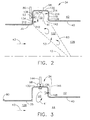
- the trapped vortex cavity 50 is utilized to produce an annular rotating vortex 41 of the fuel/air mixture more particularly illustrated in FIGS. 2-3.
- the trapped vortex cavity 50 is positioned with respect to the combustion zone 44 such that there is a aftwardly tapering frusto-conical path 63 from the cavity towards the centerline axis 12 in the combustion zone along which the combusting fuel/air mixture 53 is injected into the combustion zone 44.
- the air/fuel mixture 53 is in the shape of a conical vortex sheet generated from within the cavity and ignited by an igniter 98 positioned within or adjacent to the cavity 50.
- the trapped vortex cavity 50 includes a cavity forward wall 134, a cavity radially outer wall 130, and a cavity aft wall 148.
- a cavity opening 142 extends between the cavity forward and aft walls 134 and 148 at a radially inner end 139 of the trapped vortex cavity 50.
- the cavity opening 142 is open to combustion zone 44 and is spaced radially apart and inwardly of the cavity radially outer wall 130.
- Vortex driving aftwardly injected air 210 from the bypass air 26 is injected through air injection first holes 212 through the cavity forward wall 134 at a radial position along the forward wall near the opening 142 at the radially inner end 139 of the trapped vortex cavity 50.
- Vortex driving forwardly injected air 216 is injected through air injection second holes 214 in the cavity aft wall 148 positioned radially near the cavity radially outer wall 130.
- the circumferentially disposed annular trapped vortex cavity 50 faces radially inwardly towards the centerline axis 12 in the combustion zone 44 so as to be in direct unobstructed fluid communication with the combustion zone 44.
- the annular trapped vortex cavity 50 is located aft and downstream of the mixer 31 at a radially outer portion 122 of the combustion zone 44 for maximizing flame ignition and stabilization in the combustion zone 44 during thrust augmentation or reheat.
- Fuel may be introduced into the trapped vortex cavity 50 at one or more locations. Illustrated in FIG. 2 is a first vortex fuel tube 80 extending radially inwardly through the radially outer wall 130 of the vortex cavity 50 and operable for injecting fuel into the vortex cavity 50.
- the first vortex fuel tubes 80 include a fuel hole for injecting the fuel 75 into the vortex cavity 50 through a fuel aperture 136 in the forward wall 134 of the trapped vortex cavity 50. Some of the bypass air 26 flows through the fuel apertures 136 helping to inject the fuel into the trapped vortex cavity 50.
- the trapped vortex cavity 50 in each of the trapped vortex cavity stages 52 illustrated herein is attached to or integrally formed with the exhaust combustion liner 40.
- FIG. 3 Illustrated in FIG. 3 is another exemplary embodiment of the vortex cavity 50 having two different locations for injecting fuel into the trapped vortex cavity 50 are used.
- a second vortex fuel tube 144 extends radially inwardly to a point just radially outside of the radially outer wall 130 of the vortex cavity 50.
- the second vortex fuel tube 144 is operable to inject fuel into the vortex cavity 50 through one or more fuel apertures 136 in the radially outer wall 130 of the vortex cavity 50.
- Some of the bypass air 26 flows through the fuel apertures 136 helping to inject the fuel into the trapped vortex cavity 50.
- An alternative third vortex fuel tube 146 illustrated in phantom line to indicate it circumferentially offset and out of plane with respect to the second vortex fuel tube 144, extends radially inwardly to a point just aft or downstream of a cavity aft wall 148 of the trapped vortex cavity 50.
- the third vortex fuel tube 146 is operable to inject fuel into the vortex cavity 50 through one or more fuel apertures 136 in the aft wall 148 of the trapped vortex cavity 50. Because of the higher pressure of the bypass air 26, some of the bypass air flows through the fuel apertures 136 helping to inject the fuel into the trapped vortex cavity 50.
- igniter 98 disposed through the cavity radially outer wall 130 and operable to ignite the annular rotating vortex 41 of the fuel and air mixture and spread a flame front into the combustion zone 44.
- two or more circumferentially spaced apart igniters 98 may be used.
- the trapped vortex cavity 50 thus serves as an afterburner or augmentor to provide additional thrust for the engine by increasing the temperature of the mixture of the core gases 28 and the bypass air 26 flowing from the bypass duct 24 and through the mixer 31 into the combustion zone 44.
- the igniter 98 may not always be needed. Suitable igniters include conventional electric spark igniters (spark plugs) and, more recent, radiative plasma ignition means such as those illustrated in U.S. Patent Nos.
- the core gases 28 from the core outlet 30 flowing into the combustion zone 44 may be hot enough to ignite the fuel/air mixture of the vortex sheet.
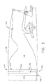
- One particular application of the trapped vortex cavity afterburner 34 is in a single expansion ramp nozzle 300 (SERN) illustrated in FIGS. 4 and 5.
- SERN single expansion ramp nozzle 300
- SERN is a two-dimensional variable area nozzle providing installed performance characteristics of low weight and low frictional drag because there is no or a smaller lower cowl.
- SERN nozzles provide thrust pitch vectoring and Low Observable (LO) exhaust nozzle technology which is being developed for current and future fighter/attack aircraft.
- LO nozzles are easily integrated cleanly with the aircraft airframe and do not degrade the aircraft's performance due to weight and drag penalties.
- the SERN nozzle 300 illustrated herein is a convergent divergent two-dimensional gas turbine engine exhaust nozzle having convergent and divergent sections 315 and 317 and a variable area throat 318 therebetween.
- the divergent section 317 includes transversely spaced apart upper and lower divergent flaps 358 and 360, respectively, extending longitudinally downstream along a nozzle axis 368, illustrated as co-linear with the centerline axis 12, and disposed between two widthwise spaced apart first and second sidewalls not illustrated herein.
- the trapped vortex cavity afterburner 34 illustrated in FIG. 4 is a single stage trapped vortex cavity afterburner 100 while the trapped vortex cavity afterburner 34 illustrated in FIG. 5 is a double stage trapped vortex cavity afterburner 102 representative of a multi-stage afterburner 104 which have two or more trapped vortex cavity stages 52.
- Each of the trapped vortex cavity stages 52 have the trapped vortex cavity 50.
- Each stage or trapped vortex cavity 50 is used to incrementally add heat to and raise the temperature of the mixture of the exhaust gas flow 43 flowing through the combustion zone 44.
- the amount of heat added by the trapped vortex cavity afterburner 34 to the exhaust gas flow 43 in the exhaust section 126 is not as much as compared to conventional augmentors using fuel injectors or fuel bars and radial and/or circumferential flameholders.
- An exemplary embodiment of the trapped vortex cavity afterburner 34 is designed to raise the temperature of the exhaust gas flow 43 in the exhaust section 126 by about 100 degrees Fahrenheit for each stage of the trapped vortex cavity 50 incorporated in the trapped vortex cavity afterburner 34.
- the stages of the trapped vortex cavity 50 in the multi-stage afterburners 104 can be initiated simultaneously or individually.
- Each of the trapped vortex cavity stages 52 may be operable to produce the same amount of additional thrust or temperature rise in the exhaust gas flow 43 flowing through the afterburner or different amounts.
- One embodiment of the trapped vortex cavity afterburner 34 may have five stages of trapped vortex cavities 50 wherein each stage is operable to produce a temperature rise of 150 degrees F in the exhaust gas flow 43 through the afterburner.
- the stages of trapped vortex cavities 50 may be ganged and ignited simultaneously or sequentially one or more at a time such that varying amounts of reheat are produced.
- Another embodiment of the trapped vortex cavity afterburner 34 may have three stages of trapped vortex cavities 50 wherein each stage is operable to produce a different temperature rise, for example 150, 250, and 350 degrees F in the exhaust gas flow 43.
- the stages of trapped vortex cavities 50 may be ganged and ignited simultaneously or sequentially one or more at a time such that varying amounts of reheat are produced.
- the trapped vortex cavity afterburner 34 illustrated in FIG. 6 is the double stage trapped vortex cavity afterburner 102 representing multi-stage afterburners 104 which have two or more trapped vortex cavity stages 52.
- Each of the trapped vortex cavity stages 52 has a chevroned shaped trapped vortex cavity 150.
- Each of the chevron shaped trapped vortex cavities 150 has zig-zag shaped leading and trailing edges 152 and 154.
- the chevron shaped trapped vortex cavity 150 may be used in single stage trapped vortex cavity afterburners 100 or multi-stage afterburners 104 to help reduce the radar signature of the trapped vortex cavity afterburner 34.
- the trapped vortex cavity afterburner 34 is illustrated in the exhaust section 126 of an exemplary medium bypass ratio turbofan gas turbine engine 10, it may be used in various other types of gas turbine engines such as a turbojet.
- exhaust flow from the turbines contain oxygen to be used for combustion by the afterburner.
- Compressor air may be flowed to the afterburner of the turbojet in order to have more oxygen for combustion.
- the trapped vortex cavity afterburner 34 provides a thrust augmentation system that is inexpensive to manufacture and produce, and has the performance to meet the requirements of low levels of thrust augmentation or reheat.
- each stage of the augmentor would produce approximately 150 degrees F of temperature rise.
- the trapped vortex cavity afterburner 34 is probably capable of providing a heat or temperature rise or temperature rise of about of 100 to 200 degrees Fahrenheit for each stage containing a single annular trapped vortex cavity 50.
- the trapped vortex cavity afterburner 34 has no need for instream flameholders and development cost, acquisition cost, and maintenance costs would be low.
- the trapped vortex cavity afterburner 34 provides improved dry performance because there are no flameholders to reduce nozzle performance.
- the trapped vortex cavity afterburner 34 decreases the weight of the engine compared to one with conventional afterburners.
- the trapped vortex cavity afterburner 34 may be used for various flight conditions calling for an additional amount of thrust for a short period of time. Takeoff and flight maneuvers are two examples of these flight conditions.
- the trapped vortex cavity afterburner 34 can be used to get overcome transonic drag rise as the engine propels an aircraft through transonic flight to supersonic flight where drag decreases and dry operation of the engine may be resumed.
Landscapes
- Engineering & Computer Science (AREA)
- Chemical & Material Sciences (AREA)
- Combustion & Propulsion (AREA)
- Mechanical Engineering (AREA)
- General Engineering & Computer Science (AREA)
- Exhaust Gas After Treatment (AREA)
- Supercharger (AREA)
Applications Claiming Priority (1)
| Application Number | Priority Date | Filing Date | Title |
|---|---|---|---|
| US11/209,918 US7225623B2 (en) | 2005-08-23 | 2005-08-23 | Trapped vortex cavity afterburner |
Publications (2)
| Publication Number | Publication Date |
|---|---|
| EP1757860A2 true EP1757860A2 (de) | 2007-02-28 |
| EP1757860A3 EP1757860A3 (de) | 2015-05-06 |
Family
ID=37453029
Family Applications (1)
| Application Number | Title | Priority Date | Filing Date |
|---|---|---|---|
| EP20060254332 Withdrawn EP1757860A3 (de) | 2005-08-23 | 2006-08-17 | Nachbrenner mit Hohlraum zur Erzeugung eingeschlossener Wirbel |
Country Status (2)
| Country | Link |
|---|---|
| US (1) | US7225623B2 (de) |
| EP (1) | EP1757860A3 (de) |
Cited By (5)
| Publication number | Priority date | Publication date | Assignee | Title |
|---|---|---|---|---|
| US9279325B2 (en) | 2012-11-08 | 2016-03-08 | General Electric Company | Turbomachine wheel assembly having slotted flanges |
| CN110686275A (zh) * | 2019-09-23 | 2020-01-14 | 中国科学院工程热物理研究所 | 一种强化掺混与火焰传播的燃烧室火焰稳定结构 |
| CN112413645A (zh) * | 2020-11-19 | 2021-02-26 | 中国航发沈阳发动机研究所 | 一种航空发动机加力点火供油方法及系统 |
| CN116592393A (zh) * | 2023-05-24 | 2023-08-15 | 中国航空发动机研究院 | 一种燃烧设备及燃气发动机 |
| CN119222581A (zh) * | 2024-10-25 | 2024-12-31 | 北京航空航天大学 | 一种多凹腔超燃冲压发动机燃烧室及其控制方法 |
Families Citing this family (103)
| Publication number | Priority date | Publication date | Assignee | Title |
|---|---|---|---|---|
| US20080196414A1 (en) * | 2005-03-22 | 2008-08-21 | Andreadis Dean E | Strut cavity pilot and fuel injector assembly |
| US7509797B2 (en) * | 2005-04-29 | 2009-03-31 | General Electric Company | Thrust vectoring missile turbojet |
| US7475545B2 (en) * | 2005-04-29 | 2009-01-13 | General Electric Company | Fladed supersonic missile turbojet |
| US7448199B2 (en) * | 2005-04-29 | 2008-11-11 | General Electric Company | Self powdered missile turbojet |
| US7424805B2 (en) * | 2005-04-29 | 2008-09-16 | General Electric Company | Supersonic missile turbojet engine |
| US7467518B1 (en) * | 2006-01-12 | 2008-12-23 | General Electric Company | Externally fueled trapped vortex cavity augmentor |
| US7779866B2 (en) * | 2006-07-21 | 2010-08-24 | General Electric Company | Segmented trapped vortex cavity |
| US8011188B2 (en) * | 2007-08-31 | 2011-09-06 | General Electric Company | Augmentor with trapped vortex cavity pilot |
| US7762086B2 (en) * | 2008-03-12 | 2010-07-27 | United Technologies Corporation | Nozzle extension assembly for ground and flight testing |
| US8286416B2 (en) * | 2008-04-02 | 2012-10-16 | Pratt & Whitney Rocketdyne, Inc. | Valve system for a gas turbine engine |
| US8402744B2 (en) * | 2008-03-22 | 2013-03-26 | Pratt & Whitney Rocketdyne, Inc. | Valve system for a gas turbine engine |
| US8578716B2 (en) * | 2008-03-22 | 2013-11-12 | United Technologies Corporation | Valve system for a gas turbine engine |
| US8240126B2 (en) * | 2008-03-22 | 2012-08-14 | Pratt & Whitney Rocketdyne, Inc. | Valve system for a gas turbine engine |
| MY156350A (en) | 2008-03-28 | 2016-02-15 | Exxonmobil Upstream Res Co | Low emission power generation and hydrocarbon recovery systems and methods |
| MY153097A (en) | 2008-03-28 | 2014-12-31 | Exxonmobil Upstream Res Co | Low emission power generation and hydrocarbon recovery systems and methods |
| BRPI0920139A2 (pt) | 2008-10-14 | 2015-12-22 | Exxonmobil Upstream Res Co | sistema de combustão, método de controle de combustão, e, sistema de combustor. |
| CN102597418A (zh) | 2009-11-12 | 2012-07-18 | 埃克森美孚上游研究公司 | 低排放发电和烃采收系统及方法 |
| US8726670B2 (en) | 2010-06-24 | 2014-05-20 | General Electric Company | Ejector purge of cavity adjacent exhaust flowpath |
| EA029301B1 (ru) | 2010-07-02 | 2018-03-30 | Эксонмобил Апстрим Рисерч Компани | Интегрированные системы для получения со(варианты) и способ производства электроэнергии |
| CA2801494C (en) | 2010-07-02 | 2018-04-17 | Exxonmobil Upstream Research Company | Stoichiometric combustion of enriched air with exhaust gas recirculation |
| MY160832A (en) | 2010-07-02 | 2017-03-31 | Exxonmobil Upstream Res Co | Stoichiometric combustion with exhaust gas recirculation and direct contact cooler |
| AU2011271636B2 (en) | 2010-07-02 | 2016-03-17 | Exxonmobil Upstream Research Company | Low emission power generation systems and methods |
| US8991189B2 (en) * | 2010-10-28 | 2015-03-31 | General Electric Company | Side-initiated augmentor for engine applications |
| US8464538B2 (en) | 2010-12-17 | 2013-06-18 | General Electric Company | Trapped vortex combustor and method of operating thereof |
| US8783605B2 (en) * | 2010-12-28 | 2014-07-22 | Rolls-Royce North American Technologies, Inc. | Flight vehicle, propulsion system and thrust vectoring system |
| TWI563166B (en) | 2011-03-22 | 2016-12-21 | Exxonmobil Upstream Res Co | Integrated generation systems and methods for generating power |
| TWI593872B (zh) | 2011-03-22 | 2017-08-01 | 艾克頌美孚上游研究公司 | 整合系統及產生動力之方法 |
| TWI564474B (zh) | 2011-03-22 | 2017-01-01 | 艾克頌美孚上游研究公司 | 於渦輪系統中控制化學計量燃燒的整合系統和使用彼之產生動力的方法 |
| TWI563165B (en) | 2011-03-22 | 2016-12-21 | Exxonmobil Upstream Res Co | Power generation system and method for generating power |
| US8943832B2 (en) | 2011-10-26 | 2015-02-03 | General Electric Company | Fuel nozzle assembly for use in turbine engines and methods of assembling same |
| CN104428490B (zh) | 2011-12-20 | 2018-06-05 | 埃克森美孚上游研究公司 | 提高的煤层甲烷生产 |
| US9074773B2 (en) * | 2012-02-07 | 2015-07-07 | General Electric Company | Combustor assembly with trapped vortex cavity |
| US9353682B2 (en) | 2012-04-12 | 2016-05-31 | General Electric Company | Methods, systems and apparatus relating to combustion turbine power plants with exhaust gas recirculation |
| US10273880B2 (en) | 2012-04-26 | 2019-04-30 | General Electric Company | System and method of recirculating exhaust gas for use in a plurality of flow paths in a gas turbine engine |
| US9784185B2 (en) | 2012-04-26 | 2017-10-10 | General Electric Company | System and method for cooling a gas turbine with an exhaust gas provided by the gas turbine |
| US10619855B2 (en) * | 2012-09-06 | 2020-04-14 | United Technologies Corporation | Fuel delivery system with a cavity coupled fuel injector |
| US9574496B2 (en) | 2012-12-28 | 2017-02-21 | General Electric Company | System and method for a turbine combustor |
| US10107495B2 (en) | 2012-11-02 | 2018-10-23 | General Electric Company | Gas turbine combustor control system for stoichiometric combustion in the presence of a diluent |
| US9869279B2 (en) | 2012-11-02 | 2018-01-16 | General Electric Company | System and method for a multi-wall turbine combustor |
| US10215412B2 (en) | 2012-11-02 | 2019-02-26 | General Electric Company | System and method for load control with diffusion combustion in a stoichiometric exhaust gas recirculation gas turbine system |
| US9599070B2 (en) | 2012-11-02 | 2017-03-21 | General Electric Company | System and method for oxidant compression in a stoichiometric exhaust gas recirculation gas turbine system |
| US9611756B2 (en) | 2012-11-02 | 2017-04-04 | General Electric Company | System and method for protecting components in a gas turbine engine with exhaust gas recirculation |
| US10100741B2 (en) | 2012-11-02 | 2018-10-16 | General Electric Company | System and method for diffusion combustion with oxidant-diluent mixing in a stoichiometric exhaust gas recirculation gas turbine system |
| US9708977B2 (en) | 2012-12-28 | 2017-07-18 | General Electric Company | System and method for reheat in gas turbine with exhaust gas recirculation |
| US9631815B2 (en) | 2012-12-28 | 2017-04-25 | General Electric Company | System and method for a turbine combustor |
| US9803865B2 (en) | 2012-12-28 | 2017-10-31 | General Electric Company | System and method for a turbine combustor |
| US20140137560A1 (en) * | 2012-11-21 | 2014-05-22 | General Electric Company | Turbomachine with trapped vortex feature |
| US10208677B2 (en) | 2012-12-31 | 2019-02-19 | General Electric Company | Gas turbine load control system |
| US9581081B2 (en) | 2013-01-13 | 2017-02-28 | General Electric Company | System and method for protecting components in a gas turbine engine with exhaust gas recirculation |
| US9512759B2 (en) | 2013-02-06 | 2016-12-06 | General Electric Company | System and method for catalyst heat utilization for gas turbine with exhaust gas recirculation |
| TW201502356A (zh) | 2013-02-21 | 2015-01-16 | Exxonmobil Upstream Res Co | 氣渦輪機排氣中氧之減少 |
| US9938861B2 (en) | 2013-02-21 | 2018-04-10 | Exxonmobil Upstream Research Company | Fuel combusting method |
| RU2637609C2 (ru) | 2013-02-28 | 2017-12-05 | Эксонмобил Апстрим Рисерч Компани | Система и способ для камеры сгорания турбины |
| WO2014137648A1 (en) | 2013-03-08 | 2014-09-12 | Exxonmobil Upstream Research Company | Power generation and methane recovery from methane hydrates |
| US9618261B2 (en) | 2013-03-08 | 2017-04-11 | Exxonmobil Upstream Research Company | Power generation and LNG production |
| US9879862B2 (en) | 2013-03-08 | 2018-01-30 | Rolls-Royce North American Technologies, Inc. | Gas turbine engine afterburner |
| TW201500635A (zh) | 2013-03-08 | 2015-01-01 | Exxonmobil Upstream Res Co | 處理廢氣以供用於提高油回收 |
| US20140250945A1 (en) | 2013-03-08 | 2014-09-11 | Richard A. Huntington | Carbon Dioxide Recovery |
| US9631542B2 (en) | 2013-06-28 | 2017-04-25 | General Electric Company | System and method for exhausting combustion gases from gas turbine engines |
| US9835089B2 (en) | 2013-06-28 | 2017-12-05 | General Electric Company | System and method for a fuel nozzle |
| TWI654368B (zh) | 2013-06-28 | 2019-03-21 | 美商艾克頌美孚上游研究公司 | 用於控制在廢氣再循環氣渦輪機系統中的廢氣流之系統、方法與媒體 |
| US9617914B2 (en) | 2013-06-28 | 2017-04-11 | General Electric Company | Systems and methods for monitoring gas turbine systems having exhaust gas recirculation |
| US9903588B2 (en) | 2013-07-30 | 2018-02-27 | General Electric Company | System and method for barrier in passage of combustor of gas turbine engine with exhaust gas recirculation |
| US9587510B2 (en) | 2013-07-30 | 2017-03-07 | General Electric Company | System and method for a gas turbine engine sensor |
| US9951658B2 (en) | 2013-07-31 | 2018-04-24 | General Electric Company | System and method for an oxidant heating system |
| US10030588B2 (en) | 2013-12-04 | 2018-07-24 | General Electric Company | Gas turbine combustor diagnostic system and method |
| US9752458B2 (en) | 2013-12-04 | 2017-09-05 | General Electric Company | System and method for a gas turbine engine |
| US10227920B2 (en) | 2014-01-15 | 2019-03-12 | General Electric Company | Gas turbine oxidant separation system |
| US9863267B2 (en) | 2014-01-21 | 2018-01-09 | General Electric Company | System and method of control for a gas turbine engine |
| US9915200B2 (en) | 2014-01-21 | 2018-03-13 | General Electric Company | System and method for controlling the combustion process in a gas turbine operating with exhaust gas recirculation |
| US10079564B2 (en) | 2014-01-27 | 2018-09-18 | General Electric Company | System and method for a stoichiometric exhaust gas recirculation gas turbine system |
| US10047633B2 (en) | 2014-05-16 | 2018-08-14 | General Electric Company | Bearing housing |
| US10060359B2 (en) | 2014-06-30 | 2018-08-28 | General Electric Company | Method and system for combustion control for gas turbine system with exhaust gas recirculation |
| US9885290B2 (en) | 2014-06-30 | 2018-02-06 | General Electric Company | Erosion suppression system and method in an exhaust gas recirculation gas turbine system |
| US10655542B2 (en) | 2014-06-30 | 2020-05-19 | General Electric Company | Method and system for startup of gas turbine system drive trains with exhaust gas recirculation |
| US9819292B2 (en) | 2014-12-31 | 2017-11-14 | General Electric Company | Systems and methods to respond to grid overfrequency events for a stoichiometric exhaust recirculation gas turbine |
| US9869247B2 (en) | 2014-12-31 | 2018-01-16 | General Electric Company | Systems and methods of estimating a combustion equivalence ratio in a gas turbine with exhaust gas recirculation |
| US10788212B2 (en) | 2015-01-12 | 2020-09-29 | General Electric Company | System and method for an oxidant passageway in a gas turbine system with exhaust gas recirculation |
| US10316746B2 (en) | 2015-02-04 | 2019-06-11 | General Electric Company | Turbine system with exhaust gas recirculation, separation and extraction |
| US10253690B2 (en) | 2015-02-04 | 2019-04-09 | General Electric Company | Turbine system with exhaust gas recirculation, separation and extraction |
| US10094566B2 (en) | 2015-02-04 | 2018-10-09 | General Electric Company | Systems and methods for high volumetric oxidant flow in gas turbine engine with exhaust gas recirculation |
| US10267270B2 (en) | 2015-02-06 | 2019-04-23 | General Electric Company | Systems and methods for carbon black production with a gas turbine engine having exhaust gas recirculation |
| US10145269B2 (en) | 2015-03-04 | 2018-12-04 | General Electric Company | System and method for cooling discharge flow |
| US10480792B2 (en) | 2015-03-06 | 2019-11-19 | General Electric Company | Fuel staging in a gas turbine engine |
| CN104929808B (zh) * | 2015-05-06 | 2017-12-29 | 中国人民解放军国防科学技术大学 | 一种火焰稳定装置及发动机 |
| US10086332B2 (en) | 2015-05-07 | 2018-10-02 | Ford Global Technologies, Llc | Exhaust flow device |
| US9822688B2 (en) | 2015-06-24 | 2017-11-21 | Ford Global Technologies, Llc | Exhaust flow device |
| CN105180211B (zh) * | 2015-09-02 | 2017-06-16 | 中国人民解放军国防科学技术大学 | 具有凹腔火焰稳定器的燃烧室及超燃冲压发动机 |
| US10066530B2 (en) | 2015-11-17 | 2018-09-04 | Ford Global Technologies, Llc | Exhaust gas mixer |
| US10704787B2 (en) * | 2016-03-30 | 2020-07-07 | General Electric Company | Closed trapped vortex cavity pilot for a gas turbine engine augmentor |
| US10823422B2 (en) | 2017-10-17 | 2020-11-03 | General Electric Company | Tangential bulk swirl air in a trapped vortex combustor for a gas turbine engine |
| US11236908B2 (en) * | 2018-10-24 | 2022-02-01 | General Electric Company | Fuel staging for rotating detonation combustor |
| US11754287B2 (en) | 2020-09-11 | 2023-09-12 | Raytheon Technologies Corporation | Fuel injector assembly for a turbine engine |
| US11421883B2 (en) | 2020-09-11 | 2022-08-23 | Raytheon Technologies Corporation | Fuel injector assembly with a helical swirler passage for a turbine engine |
| US11649964B2 (en) | 2020-12-01 | 2023-05-16 | Raytheon Technologies Corporation | Fuel injector assembly for a turbine engine |
| CN113405119B (zh) * | 2021-05-07 | 2022-04-08 | 南京航空航天大学 | 一种旋流驻涡分区燃烧室 |
| CN113551262B (zh) * | 2021-07-19 | 2022-06-14 | 南昌航空大学 | 一种带新月沙丘型面的支板火焰稳定器 |
| US11808455B2 (en) | 2021-11-24 | 2023-11-07 | Rtx Corporation | Gas turbine engine combustor with integral fuel conduit(s) |
| US11846249B1 (en) | 2022-09-02 | 2023-12-19 | Rtx Corporation | Gas turbine engine with integral bypass duct |
| US12078357B2 (en) * | 2022-12-09 | 2024-09-03 | General Electric Company | Rotating detonation-enabled augmentor systems |
| US12116934B2 (en) | 2023-02-10 | 2024-10-15 | Rtx Corporation | Turbine engine fuel injector with oxygen circuit |
| US12352224B2 (en) | 2023-10-05 | 2025-07-08 | General Electric Company | Serial rotating detonation combustor systems |
| US12535214B2 (en) | 2024-04-19 | 2026-01-27 | Rtx Corporation | Attaching powerplant structures together using fuel injector bolts |
Citations (4)
| Publication number | Priority date | Publication date | Assignee | Title |
|---|---|---|---|---|
| US5367871A (en) | 1992-07-27 | 1994-11-29 | General Electric Company | Aircraft engine ignition system |
| US5442907A (en) | 1994-04-04 | 1995-08-22 | Aero-Plasma, Inc. | Bootstrap re-ignition system for aircraft jet engine |
| US5565118A (en) | 1994-04-04 | 1996-10-15 | Asquith; Joseph G. | Self starting plasma plume igniter for aircraft jet engine |
| US5640841A (en) | 1995-05-08 | 1997-06-24 | Crosby; Rulon | Plasma torch ignition for low NOx combustion turbine combustor with monitoring means and plasma generation control means |
Family Cites Families (9)
| Publication number | Priority date | Publication date | Assignee | Title |
|---|---|---|---|---|
| DE2937631A1 (de) * | 1979-09-18 | 1981-04-02 | Daimler-Benz Ag, 7000 Stuttgart | Brennkammer fuer gasturbinen |
| US5857339A (en) * | 1995-05-23 | 1999-01-12 | The United States Of America As Represented By The Secretary Of The Air Force | Combustor flame stabilizing structure |
| US5791148A (en) * | 1995-06-07 | 1998-08-11 | General Electric Company | Liner of a gas turbine engine combustor having trapped vortex cavity |
| US6286298B1 (en) * | 1998-12-18 | 2001-09-11 | General Electric Company | Apparatus and method for rich-quench-lean (RQL) concept in a gas turbine engine combustor having trapped vortex cavity |
| US6295801B1 (en) * | 1998-12-18 | 2001-10-02 | General Electric Company | Fuel injector bar for gas turbine engine combustor having trapped vortex cavity |
| US6481209B1 (en) * | 2000-06-28 | 2002-11-19 | General Electric Company | Methods and apparatus for decreasing combustor emissions with swirl stabilized mixer |
| US6735949B1 (en) * | 2002-06-11 | 2004-05-18 | General Electric Company | Gas turbine engine combustor can with trapped vortex cavity |
| US6968694B2 (en) * | 2003-03-13 | 2005-11-29 | United Technologies Corporation | Augmentor |
| US6983601B2 (en) * | 2004-05-28 | 2006-01-10 | General Electric Company | Method and apparatus for gas turbine engines |
-
2005
- 2005-08-23 US US11/209,918 patent/US7225623B2/en active Active
-
2006
- 2006-08-17 EP EP20060254332 patent/EP1757860A3/de not_active Withdrawn
Patent Citations (4)
| Publication number | Priority date | Publication date | Assignee | Title |
|---|---|---|---|---|
| US5367871A (en) | 1992-07-27 | 1994-11-29 | General Electric Company | Aircraft engine ignition system |
| US5442907A (en) | 1994-04-04 | 1995-08-22 | Aero-Plasma, Inc. | Bootstrap re-ignition system for aircraft jet engine |
| US5565118A (en) | 1994-04-04 | 1996-10-15 | Asquith; Joseph G. | Self starting plasma plume igniter for aircraft jet engine |
| US5640841A (en) | 1995-05-08 | 1997-06-24 | Crosby; Rulon | Plasma torch ignition for low NOx combustion turbine combustor with monitoring means and plasma generation control means |
Cited By (6)
| Publication number | Priority date | Publication date | Assignee | Title |
|---|---|---|---|---|
| US9279325B2 (en) | 2012-11-08 | 2016-03-08 | General Electric Company | Turbomachine wheel assembly having slotted flanges |
| CN110686275A (zh) * | 2019-09-23 | 2020-01-14 | 中国科学院工程热物理研究所 | 一种强化掺混与火焰传播的燃烧室火焰稳定结构 |
| CN112413645A (zh) * | 2020-11-19 | 2021-02-26 | 中国航发沈阳发动机研究所 | 一种航空发动机加力点火供油方法及系统 |
| CN112413645B (zh) * | 2020-11-19 | 2022-06-07 | 中国航发沈阳发动机研究所 | 一种航空发动机加力点火供油方法及系统 |
| CN116592393A (zh) * | 2023-05-24 | 2023-08-15 | 中国航空发动机研究院 | 一种燃烧设备及燃气发动机 |
| CN119222581A (zh) * | 2024-10-25 | 2024-12-31 | 北京航空航天大学 | 一种多凹腔超燃冲压发动机燃烧室及其控制方法 |
Also Published As
| Publication number | Publication date |
|---|---|
| EP1757860A3 (de) | 2015-05-06 |
| US7225623B2 (en) | 2007-06-05 |
| US20070044476A1 (en) | 2007-03-01 |
Similar Documents
| Publication | Publication Date | Title |
|---|---|---|
| US7225623B2 (en) | Trapped vortex cavity afterburner | |
| EP1939438B1 (de) | Turbofan mit Düsenverbrennung und Mischströmung | |
| CN109028146B (zh) | 混合燃烧器组件和操作方法 | |
| US8011188B2 (en) | Augmentor with trapped vortex cavity pilot | |
| US6983601B2 (en) | Method and apparatus for gas turbine engines | |
| US6883302B2 (en) | Methods and apparatus for generating gas turbine engine thrust with a pulse detonation thrust augmenter | |
| US7437876B2 (en) | Augmenter swirler pilot | |
| US7596950B2 (en) | Augmentor radial fuel spray bar with counterswirling heat shield | |
| EP1808644B1 (de) | Nachbrenner mit hohlraum zum erzeugen eingeschlossener wirbel | |
| EP2400221B1 (de) | Ejektorspülung eines neben einem abgasfliessweg liegenden hohlraums | |
| US6868665B2 (en) | Methods and apparatus for operating gas turbine engines | |
| US7779866B2 (en) | Segmented trapped vortex cavity | |
| US8991189B2 (en) | Side-initiated augmentor for engine applications | |
| Grammel Jr et al. | Segmented trapped vortex cavity |
Legal Events
| Date | Code | Title | Description |
|---|---|---|---|
| PUAI | Public reference made under article 153(3) epc to a published international application that has entered the european phase |
Free format text: ORIGINAL CODE: 0009012 |
|
| AK | Designated contracting states |
Kind code of ref document: A2 Designated state(s): AT BE BG CH CY CZ DE DK EE ES FI FR GB GR HU IE IS IT LI LT LU LV MC NL PL PT RO SE SI SK TR |
|
| AX | Request for extension of the european patent |
Extension state: AL BA HR MK YU |
|
| PUAL | Search report despatched |
Free format text: ORIGINAL CODE: 0009013 |
|
| AK | Designated contracting states |
Kind code of ref document: A3 Designated state(s): AT BE BG CH CY CZ DE DK EE ES FI FR GB GR HU IE IS IT LI LT LU LV MC NL PL PT RO SE SI SK TR |
|
| AX | Request for extension of the european patent |
Extension state: AL BA HR MK RS |
|
| RIC1 | Information provided on ipc code assigned before grant |
Ipc: F23R 3/20 20060101AFI20150331BHEP |
|
| 17P | Request for examination filed |
Effective date: 20151106 |
|
| RBV | Designated contracting states (corrected) |
Designated state(s): AT BE BG CH CY CZ DE DK EE ES FI FR GB GR HU IE IS IT LI LT LU LV MC NL PL PT RO SE SI SK TR |
|
| AKX | Designation fees paid |
Designated state(s): DE FR GB IT SE |
|
| AXX | Extension fees paid |
Extension state: BA Extension state: RS Extension state: MK Extension state: AL Extension state: HR |
|
| 17Q | First examination report despatched |
Effective date: 20170420 |
|
| STAA | Information on the status of an ep patent application or granted ep patent |
Free format text: STATUS: THE APPLICATION IS DEEMED TO BE WITHDRAWN |
|
| 18D | Application deemed to be withdrawn |
Effective date: 20200603 |