EP1758193A1 - Pile à combustible avec convertisseur de puissance refroidi par eau - Google Patents
Pile à combustible avec convertisseur de puissance refroidi par eau Download PDFInfo
- Publication number
- EP1758193A1 EP1758193A1 EP06016732A EP06016732A EP1758193A1 EP 1758193 A1 EP1758193 A1 EP 1758193A1 EP 06016732 A EP06016732 A EP 06016732A EP 06016732 A EP06016732 A EP 06016732A EP 1758193 A1 EP1758193 A1 EP 1758193A1
- Authority
- EP
- European Patent Office
- Prior art keywords
- radiating
- stack unit
- fuel
- unit
- water
- Prior art date
- Legal status (The legal status is an assumption and is not a legal conclusion. Google has not performed a legal analysis and makes no representation as to the accuracy of the status listed.)
- Withdrawn
Links
- 239000000446 fuel Substances 0.000 title claims abstract description 73
- XLYOFNOQVPJJNP-UHFFFAOYSA-N water Substances O XLYOFNOQVPJJNP-UHFFFAOYSA-N 0.000 claims abstract description 75
- UFHFLCQGNIYNRP-UHFFFAOYSA-N Hydrogen Chemical compound [H][H] UFHFLCQGNIYNRP-UHFFFAOYSA-N 0.000 claims abstract description 30
- 229910052739 hydrogen Inorganic materials 0.000 claims abstract description 19
- 239000001257 hydrogen Substances 0.000 claims abstract description 19
- 230000005611 electricity Effects 0.000 claims abstract description 16
- 239000007789 gas Substances 0.000 claims abstract description 15
- 238000010438 heat treatment Methods 0.000 claims abstract description 10
- 238000001816 cooling Methods 0.000 claims abstract description 8
- 238000003487 electrochemical reaction Methods 0.000 claims abstract description 8
- QVGXLLKOCUKJST-UHFFFAOYSA-N atomic oxygen Chemical compound [O] QVGXLLKOCUKJST-UHFFFAOYSA-N 0.000 claims abstract description 7
- 239000008236 heating water Substances 0.000 claims abstract description 7
- 229910052760 oxygen Inorganic materials 0.000 claims abstract description 7
- 239000001301 oxygen Substances 0.000 claims abstract description 7
- 238000003780 insertion Methods 0.000 claims description 5
- 230000037431 insertion Effects 0.000 claims description 5
- CURLTUGMZLYLDI-UHFFFAOYSA-N Carbon dioxide Chemical compound O=C=O CURLTUGMZLYLDI-UHFFFAOYSA-N 0.000 description 8
- 238000006243 chemical reaction Methods 0.000 description 8
- UGFAIRIUMAVXCW-UHFFFAOYSA-N Carbon monoxide Chemical compound [O+]#[C-] UGFAIRIUMAVXCW-UHFFFAOYSA-N 0.000 description 6
- 229910002091 carbon monoxide Inorganic materials 0.000 description 6
- 238000000034 method Methods 0.000 description 5
- 229910002092 carbon dioxide Inorganic materials 0.000 description 4
- 239000001569 carbon dioxide Substances 0.000 description 4
- 239000003792 electrolyte Substances 0.000 description 4
- 230000005855 radiation Effects 0.000 description 4
- OKKJLVBELUTLKV-UHFFFAOYSA-N Methanol Chemical compound OC OKKJLVBELUTLKV-UHFFFAOYSA-N 0.000 description 3
- 230000003647 oxidation Effects 0.000 description 3
- 238000007254 oxidation reaction Methods 0.000 description 3
- NINIDFKCEFEMDL-UHFFFAOYSA-N Sulfur Chemical compound [S] NINIDFKCEFEMDL-UHFFFAOYSA-N 0.000 description 2
- 239000008186 active pharmaceutical agent Substances 0.000 description 2
- 230000005540 biological transmission Effects 0.000 description 2
- 239000003245 coal Substances 0.000 description 2
- 238000006477 desulfuration reaction Methods 0.000 description 2
- 230000023556 desulfurization Effects 0.000 description 2
- GPRLSGONYQIRFK-UHFFFAOYSA-N hydron Chemical compound [H+] GPRLSGONYQIRFK-UHFFFAOYSA-N 0.000 description 2
- 239000003949 liquefied natural gas Substances 0.000 description 2
- 230000000191 radiation effect Effects 0.000 description 2
- 238000007670 refining Methods 0.000 description 2
- 238000002407 reforming Methods 0.000 description 2
- 229910052717 sulfur Inorganic materials 0.000 description 2
- 239000011593 sulfur Substances 0.000 description 2
- -1 LNG) Chemical compound 0.000 description 1
- 238000010276 construction Methods 0.000 description 1
- 230000000694 effects Effects 0.000 description 1
- 238000006056 electrooxidation reaction Methods 0.000 description 1
- 238000003912 environmental pollution Methods 0.000 description 1
- 239000003502 gasoline Substances 0.000 description 1
- 239000000463 material Substances 0.000 description 1
- 230000004048 modification Effects 0.000 description 1
- 238000012986 modification Methods 0.000 description 1
- 238000005057 refrigeration Methods 0.000 description 1
- 238000000629 steam reforming Methods 0.000 description 1
- 239000000126 substance Substances 0.000 description 1
Images



Classifications
-
- H—ELECTRICITY
- H02—GENERATION; CONVERSION OR DISTRIBUTION OF ELECTRIC POWER
- H02M—APPARATUS FOR CONVERSION BETWEEN AC AND AC, BETWEEN AC AND DC, OR BETWEEN DC AND DC, AND FOR USE WITH MAINS OR SIMILAR POWER SUPPLY SYSTEMS; CONVERSION OF DC OR AC INPUT POWER INTO SURGE OUTPUT POWER; CONTROL OR REGULATION THEREOF
- H02M7/00—Conversion of AC power input into DC power output; Conversion of DC power input into AC power output
- H02M7/003—Constructional details, e.g. physical layout, assembly, wiring or busbar connections
-
- H—ELECTRICITY
- H01—ELECTRIC ELEMENTS
- H01M—PROCESSES OR MEANS, e.g. BATTERIES, FOR THE DIRECT CONVERSION OF CHEMICAL ENERGY INTO ELECTRICAL ENERGY
- H01M8/00—Fuel cells; Manufacture thereof
- H01M8/04—Auxiliary arrangements, e.g. for control of pressure or for circulation of fluids
- H01M8/04007—Auxiliary arrangements, e.g. for control of pressure or for circulation of fluids related to heat exchange
- H01M8/04029—Heat exchange using liquids
-
- H—ELECTRICITY
- H01—ELECTRIC ELEMENTS
- H01M—PROCESSES OR MEANS, e.g. BATTERIES, FOR THE DIRECT CONVERSION OF CHEMICAL ENERGY INTO ELECTRICAL ENERGY
- H01M2250/00—Fuel cells for particular applications; Specific features of fuel cell system
- H01M2250/40—Combination of fuel cells with other energy production systems
- H01M2250/405—Cogeneration of heat or hot water
-
- H—ELECTRICITY
- H01—ELECTRIC ELEMENTS
- H01M—PROCESSES OR MEANS, e.g. BATTERIES, FOR THE DIRECT CONVERSION OF CHEMICAL ENERGY INTO ELECTRICAL ENERGY
- H01M8/00—Fuel cells; Manufacture thereof
- H01M8/04—Auxiliary arrangements, e.g. for control of pressure or for circulation of fluids
- H01M8/04007—Auxiliary arrangements, e.g. for control of pressure or for circulation of fluids related to heat exchange
- H01M8/04052—Storage of heat in the fuel cell system
-
- H—ELECTRICITY
- H01—ELECTRIC ELEMENTS
- H01M—PROCESSES OR MEANS, e.g. BATTERIES, FOR THE DIRECT CONVERSION OF CHEMICAL ENERGY INTO ELECTRICAL ENERGY
- H01M8/00—Fuel cells; Manufacture thereof
- H01M8/06—Combination of fuel cells with means for production of reactants or for treatment of residues
- H01M8/0606—Combination of fuel cells with means for production of reactants or for treatment of residues with means for production of gaseous reactants
- H01M8/0612—Combination of fuel cells with means for production of reactants or for treatment of residues with means for production of gaseous reactants from carbon-containing material
- H01M8/0618—Reforming processes, e.g. autothermal, partial oxidation or steam reforming
-
- Y—GENERAL TAGGING OF NEW TECHNOLOGICAL DEVELOPMENTS; GENERAL TAGGING OF CROSS-SECTIONAL TECHNOLOGIES SPANNING OVER SEVERAL SECTIONS OF THE IPC; TECHNICAL SUBJECTS COVERED BY FORMER USPC CROSS-REFERENCE ART COLLECTIONS [XRACs] AND DIGESTS
- Y02—TECHNOLOGIES OR APPLICATIONS FOR MITIGATION OR ADAPTATION AGAINST CLIMATE CHANGE
- Y02B—CLIMATE CHANGE MITIGATION TECHNOLOGIES RELATED TO BUILDINGS, e.g. HOUSING, HOUSE APPLIANCES OR RELATED END-USER APPLICATIONS
- Y02B90/00—Enabling technologies or technologies with a potential or indirect contribution to GHG emissions mitigation
- Y02B90/10—Applications of fuel cells in buildings
-
- Y—GENERAL TAGGING OF NEW TECHNOLOGICAL DEVELOPMENTS; GENERAL TAGGING OF CROSS-SECTIONAL TECHNOLOGIES SPANNING OVER SEVERAL SECTIONS OF THE IPC; TECHNICAL SUBJECTS COVERED BY FORMER USPC CROSS-REFERENCE ART COLLECTIONS [XRACs] AND DIGESTS
- Y02—TECHNOLOGIES OR APPLICATIONS FOR MITIGATION OR ADAPTATION AGAINST CLIMATE CHANGE
- Y02E—REDUCTION OF GREENHOUSE GAS [GHG] EMISSIONS, RELATED TO ENERGY GENERATION, TRANSMISSION OR DISTRIBUTION
- Y02E60/00—Enabling technologies; Technologies with a potential or indirect contribution to GHG emissions mitigation
- Y02E60/30—Hydrogen technology
- Y02E60/50—Fuel cells
Definitions
- the present invention relates to a fuel cell having a water type radiating device, and particularly, to a fuel cell having a water type radiating device which is capable of heating water stored in a water tank (or water container) inside a fuel cell by collecting (retrieving) heat radiated out of the fuel cell through a radiating plate, and of improving a radiation effect by employing a water type radiation structure.
- Thermal power or water power generated from power plants is used to generate electric power used in buildings in recent times.
- the electric energy generated from the power plants is supplied to buildings (e.g., each house) located in each region through a power transmission line, and the supplied electric energy is used to operate TV sets, refrigeration, air conditioners, and the like, resulting in a convenient living.
- a fuel cell is being developed such that an excellent energy efficiency can be provided and environment-friendly electric energy can be generated.
- the fuel cell refers to a device for directly converting chemical energy contained in the fuel into the electric energy by virtue of an electrochemical reaction between a fuel sequentially supplied from the exterior and air.
- Fig. 1 is a schematic view showing a structure of a related art fuel cell having a radiating device
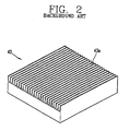
- Fig. 2 is a perspective view showing a structure of a radiating plate of Fig. 1.
- a related art fuel cell includes a fuel supply unit 10 for supplying a certain amount of fuel, a reformer 20 for generating a hydrogen containing gas containing a hydrogen gas and heat by receiving the fuel from the fuel supply unit 10, a stack unit 30 for generating an electricity and heat according to an electrochemical reaction between the hydrogen gas generated from the reformer 20 and oxygen separately supplied, a power converter 40 for converting the electricity generated from the stack unit 30 into an Alternating Current (AC), and a water tank (or water container) 50 for supplying hot water by use of the heat generated from the stack unit 30.
- AC Alternating Current
- the reformer 20 includes a desulfurization reactor DS 21 for introducing the fuel supplied from the fuel supply unit 10, water and air to thus remove sulfur contained in the fuel, a steam reformer SR 22 for reacting the fuel with steam, a high temperature steam reactor HTS 23 for reacting carbon monoxide with steam, a low temperature steam reactor LTS 24 for converting the carbon monoxide into carbon dioxide, a partial oxidation reactor PRO 25 for converting non-oxidized carbon monoxide into carbon dioxide, a reaction furnace 26 for generating hydrogen from the fuel by a reforming process and a hydrogen refining process, and a burner 27 for supplying heat required to the reaction furnace 26 by being contact-coupled to the reaction furnace 26.
- a desulfurization reactor DS 21 for introducing the fuel supplied from the fuel supply unit 10, water and air to thus remove sulfur contained in the fuel
- a steam reformer SR 22 for reacting the fuel with steam
- HTS 23 high temperature steam reactor
- LTS 24 low temperature steam reactor LTS 24 for converting the carbon monoxide
- the stack unit 30 is implemented by stacking a plurality of unit cells, and includes an anode 31, an electrolyte film 32, and a cathode 33.
- the power converter 40 refers to a device for converting a Direct Current (DC) generated from the stack unit 30 into an AC which can be used in the houses.
- the power converter 40 is provided with a plurality of devices (not shown) therein for operating a converter 41 and an inverter 42. Each device is coupled to a radiating plate so as to radiate heat generated therefrom to the exterior.
- a plurality of radiating pins 43a having a certain length upwardly along a thickness direction of the radiating plate 43 are disposed at an upper end surface of the radiating plate 43 to thus fast perform the radiation of the radiating plate 43 by increasing a contact area between the radiating plate 43 and air.
- a radiating fan 44 is disposed at one side of the radiating plate 43 to thus cool the radiating plate 43.
- a connection line 60 through which water within the water tank 50 flows in and flows out connects a lower end portion of the stack unit 30 and a lower end portion of the water tank 50 to thus enable a heating of the water contained in the water tank 50 by use of the heat generated from the stack unit 30.
- connection line 60 By connecting the connection line 60 to the lower end portion of the water tank 50, relatively cold water is positioned at a lower side of the water tank 50 and relatively hot water is positioned at the upper side thereof according to a convection of the water, thereby reducing a time taken by heating the water.
- the heat generated from the power converter 40 is discharged out of the power converter 40 by using the radiating pins 43a and the radiating fan 44 of the radiating plate 43.
- an air cooling method used in the radiating plate 43 does not provide a fast cooling effect.
- the heat generated from the power converter 40 is not collected but discharged outside, which results in an inefficient usage of energy.
- an object of the present invention is to provide a fuel cell having a water type radiating device which is capable of heating water stored in a water tank (or water container) inside a fuel cell by collecting (retrieving) heat radiated out of the fuel cell through a radiating plate, and of improving a radiation effect by employing a water type radiation structure.
- a fuel cell having a water type radiating device comprising a fuel supply unit for supplying a certain rate of fuel, a reformer for generating a hydrogen containing gas containing a hydrogen gas by receiving the fuel from the fuel supply unit, a stack unit for generating an electricity and heat according to an electrochemical reaction between the hydrogen containing gas generated from the reformer and oxygen separately supplied, a water tank connected to one side of the stack unit for heating water contained therein by use of the heat generated from the stack unit, a power converter connected to one side of the stack unit for converting the electricity generated from the stack unit into an alternating current and having a plurality of radiating plates, and a forcible radiating unit for forcibly cooling the radiating plates and for heating the water contained in the water tank.
- the present invention provides a fuel cell having a water type radiating device comprising a fuel supply unit for supplying a certain rate of fuel, a reformer for generating a hydrogen containing gas containing a hydrogen gas by receiving the fuel from the fuel supply unit, a stack unit for generating an electricity and heat according to an electrochemical reaction between the hydrogen containing gas generated from the reformer and oxygen separately supplied, a water tank connected to one side of the stack unit for heating water contained therein by use of the heat generated from the stack unit, a power converter connected to one side of the stack unit for converting the electricity generated from the stack unit into an alternating current and having a plurality of radiating plates, and a forcible radiating unit for forcibly cooling the radiating plates and for heating the water contained in the water tank.
- Fig. 3 is a schematic view showing a structure of a fuel cell having a radiating device in accordance with one embodiment of the present invention
- Fig. 4 is a perspective view showing a radiating plate of Fig. 3.
- a fuel cell having a water type radiating device in accordance with an embodiment of the present invention includes a fuel supply unit 100 for supplying a certain rate of fuel, a reformer 200 for generating a hydrogen containing gas containing a hydrogen gas by receiving the fuel from the fuel supply unit 100, a stack unit 300 for generating an electricity and heat according to an electrochemical reaction between the hydrogen containing gas generated from the reformer 200 and oxygen separately supplied, a water tank 500 connected to one side of the stack unit 300 for heating water contained therein by use of the heat generated from the stack unit 300, a power converter 400 connected to one side of the stack unit 300 for converting the electricity generated from the stack unit 300 into an alternating current and having a plurality of radiating plates 430, and a forcible radiating unit for forcibly cooling the radiating plates 430 and for heating the water contained in the water tank 500.
- the reformer 200 includes a desulfurization reactor DS 210 for introducing the fuel supplied from the fuel supply unit 100, water and air to thus remove sulfur contained in the fuel, a steam reformer SR 220 for reacting the fuel with steam, a high temperature steam reactor HTS 230 for reacting carbon monoxide with steam, a low temperature steam reactor LTS 240 for converting the carbon monoxide into carbon dioxide, a partial oxidation reactor PRO 250 for converting non-oxidized carbon monoxide into carbon dioxide, a reaction furnace 260 for generating hydrogen from the fuel by a reforming process and a hydrogen refining process, and a burner 270 for supplying heat required to the reaction furnace 260 by being contact-coupled to the reaction furnace 260.
- a desulfurization reactor DS 210 for introducing the fuel supplied from the fuel supply unit 100, water and air to thus remove sulfur contained in the fuel
- a steam reformer SR 220 for reacting the fuel with steam
- HTS 230 high temperature steam reactor
- LTS 240 low
- the stack unit 300 is implemented by stacking a plurality of unit cells, and includes an anode 310, an electrolyte film 320, and a cathode 330.
- the power converter 400 refers to a device for converting a Direct Current (DC) generated from the stack unit 300 into an AC which can be used in the houses.
- the power converter 400 is provided with a plurality of devices (not shown) therein for operating a converter 410 and an inverter 420. Each device is coupled to a radiating plate 430 so as to radiate heat generated therefrom to the exterior.
- a plurality of radiating pins 431 having a certain length upwardly along a thickness direction of the radiating plate 430 are disposed at an upper end surface of the radiating plate 43 to thus fast perform the radiation of the radiating plate 430 by increasing a contact area between the radiating plate 430 and air.
- a plurality of insertion holes 432 are formed through one side of the radiating plate 430 to thus be coupled to a divergence pipe 700 which is to be explained later in a manner of an insertion.
- a connection line 600 through which water within the water tank 500 flows in and flows out is installed at a lower end portion of the stack unit 300 and a lower end portion of the water tank 500 to thus enable a heating of the water contained in the water tank 500 by use of the heat generated from the stack unit 300.
- connection line 600 By connecting the connection line 600 to the lower end portion of the water tank 500, relatively cold water is positioned at a lower side of the water tank 500 and relatively hot water is positioned at the upper side thereof according to a convection of the water, thereby reducing a time taken by heating the water.
- the forcible radiating unit refers to the divergence pipe 700 which is diverged from the connection line 600 which connects the stack unit 300 and the water tank 500 and then merged with the connection line 600 via the radiating plates 430 in order to be in contact with the radiating plates 430.
- the divergence pipe 700 is inserted into the insertion holes 432 of the radiating plates 430 to be in contact with the radiating plates 430, and then connected to one side of the connection line 600 to allow water within the water tank to flow therethrough.
- the forcible radiating unit may be passed through the radiating plates 430 in a manner of a zigzag shape.
- the fuel supply unit 100 supplies to the reformer 200 water and fuel (e.g., methanol, liquefied natural gas (i.e., LNG), gasoline, or the like), a steam reforming and a partial oxidation are compositively executed in the reformer 200, thereby generating a hydrogen containing gas which contains a hydrogen gas, reaction heat, and water.
- fuel e.g., methanol, liquefied natural gas (i.e., LNG), gasoline, or the like
- a steam reforming and a partial oxidation are compositively executed in the reformer 200, thereby generating a hydrogen containing gas which contains a hydrogen gas, reaction heat, and water.
- a hydrogen gas H 2 is supplied to a side of the anode 310 to generate an electrochemical oxidation reaction. Then, the hydrogen gas H 2 is ionized into a hydrogen ion H+ and an electron e- to thus be oxidized. The ionized hydrogen ion H+ is moved toward the cathode 330 via the electrolyte film 320 and the electron e- is moved toward the anode 310 via the electrolyte film 320, thereby generating an electricity, heat and water. The electricity generated from the stack unit 300 is converted into the alternating current (AC) by the power converter 400 to thus operate electrical products.
- AC alternating current
- the water contained in the water tank 500 flows into the stack unit 300 via the connection line 600 disposed between the stack unit 300 and the water tank 500 to be heated by the heat generated from the stack unit 300.
- the heated water is discharged out of the stack unit 300.
- the discharged water is in contact with the radiating plates 430 via the divergence pipe 700 and then is heated into a higher temperature, to thereafter flow into the water tank 500.
- Such processes are repeatedly performed so as to enable the heating of the water contained in the water tank more fast.
- the radiating plates 430 can be cooled more fast without using a separate radiating fan as compared to the air cooling method used in the related art fuel cell.
Landscapes
- Engineering & Computer Science (AREA)
- Life Sciences & Earth Sciences (AREA)
- Manufacturing & Machinery (AREA)
- Sustainable Development (AREA)
- Sustainable Energy (AREA)
- Chemical & Material Sciences (AREA)
- Chemical Kinetics & Catalysis (AREA)
- Electrochemistry (AREA)
- General Chemical & Material Sciences (AREA)
- Power Engineering (AREA)
- Fuel Cell (AREA)
Applications Claiming Priority (1)
| Application Number | Priority Date | Filing Date | Title |
|---|---|---|---|
| KR20050077000 | 2005-08-22 |
Publications (1)
| Publication Number | Publication Date |
|---|---|
| EP1758193A1 true EP1758193A1 (fr) | 2007-02-28 |
Family
ID=37056503
Family Applications (1)
| Application Number | Title | Priority Date | Filing Date |
|---|---|---|---|
| EP06016732A Withdrawn EP1758193A1 (fr) | 2005-08-22 | 2006-08-10 | Pile à combustible avec convertisseur de puissance refroidi par eau |
Country Status (4)
| Country | Link |
|---|---|
| US (1) | US20070042238A1 (fr) |
| EP (1) | EP1758193A1 (fr) |
| CN (1) | CN1921202A (fr) |
| RU (1) | RU2327258C1 (fr) |
Cited By (1)
| Publication number | Priority date | Publication date | Assignee | Title |
|---|---|---|---|---|
| AT516241A1 (de) * | 2014-09-04 | 2016-03-15 | Fronius Int Gmbh | Wechselrichter zur Fluiderwärmung |
Families Citing this family (8)
| Publication number | Priority date | Publication date | Assignee | Title |
|---|---|---|---|---|
| US20040171091A1 (en) * | 2003-02-27 | 2004-09-02 | Cell Work, Inc. | Standardized evaluation of therapeutic efficacy based on cellular biomarkers |
| US8921102B2 (en) * | 2005-07-29 | 2014-12-30 | Gpb Scientific, Llc | Devices and methods for enrichment and alteration of circulating tumor cells and other particles |
| US20080050739A1 (en) * | 2006-06-14 | 2008-02-28 | Roland Stoughton | Diagnosis of fetal abnormalities using polymorphisms including short tandem repeats |
| US8137912B2 (en) | 2006-06-14 | 2012-03-20 | The General Hospital Corporation | Methods for the diagnosis of fetal abnormalities |
| EP2029779A4 (fr) | 2006-06-14 | 2010-01-20 | Living Microsystems Inc | Utilisation de génotypage snp fortement parallèle pour diagnostic fétal |
| EP2589668A1 (fr) | 2006-06-14 | 2013-05-08 | Verinata Health, Inc | Analyse de cellules rares utilisant la division d'échantillons et les marqueurs d'ADN |
| ES2620012T3 (es) | 2008-09-20 | 2017-06-27 | The Board Of Trustees Of The Leland Stanford Junior University | Diagnóstico no invasivo de la aneuploidia fetal por secuenciación |
| US8187979B2 (en) * | 2009-12-23 | 2012-05-29 | Varian Semiconductor Equipment Associates, Inc. | Workpiece patterning with plasma sheath modulation |
Citations (5)
| Publication number | Priority date | Publication date | Assignee | Title |
|---|---|---|---|---|
| JPH09161829A (ja) * | 1995-11-30 | 1997-06-20 | Toshiba Corp | 燃料電池発電設備 |
| JP2002075427A (ja) * | 2000-09-05 | 2002-03-15 | Toyota Industries Corp | 燃料電池発電システム |
| US6569550B2 (en) * | 1999-12-21 | 2003-05-27 | Valeo Klimasysteme Gmbh | Vehicle cooling/heating circuit |
| US20030157381A1 (en) * | 2000-02-17 | 2003-08-21 | Van Andel Eleonoor | Polymer electrolyte fuel cell based heat and power generation unit |
| JP2004328914A (ja) * | 2003-04-25 | 2004-11-18 | Nissan Motor Co Ltd | 燃料電池搭載車両の電子部品冷却装置 |
Family Cites Families (5)
| Publication number | Priority date | Publication date | Assignee | Title |
|---|---|---|---|---|
| JP3480451B2 (ja) * | 2001-05-22 | 2003-12-22 | 日産自動車株式会社 | 燃料電池システム |
| KR100818558B1 (ko) * | 2002-03-12 | 2008-04-01 | 주식회사 엘지이아이 | 연료전지 시스템의 스택 냉각 장치 및 이를 이용한 과부하방지 방법 및 연료/공기 공급량 제어 방법 |
| RU2210840C1 (ru) * | 2002-04-09 | 2003-08-20 | Темерко Александр Викторович | Электроэнергетическая система |
| JP4252779B2 (ja) * | 2002-08-21 | 2009-04-08 | 大阪瓦斯株式会社 | 燃料電池設備 |
| JP2005100693A (ja) * | 2003-09-22 | 2005-04-14 | Toyota Industries Corp | 燃料電池の冷却システム |
-
2006
- 2006-08-10 EP EP06016732A patent/EP1758193A1/fr not_active Withdrawn
- 2006-08-21 CN CNA2006101213848A patent/CN1921202A/zh active Pending
- 2006-08-21 US US11/466,057 patent/US20070042238A1/en not_active Abandoned
- 2006-08-21 RU RU2006130313/09A patent/RU2327258C1/ru not_active IP Right Cessation
Patent Citations (5)
| Publication number | Priority date | Publication date | Assignee | Title |
|---|---|---|---|---|
| JPH09161829A (ja) * | 1995-11-30 | 1997-06-20 | Toshiba Corp | 燃料電池発電設備 |
| US6569550B2 (en) * | 1999-12-21 | 2003-05-27 | Valeo Klimasysteme Gmbh | Vehicle cooling/heating circuit |
| US20030157381A1 (en) * | 2000-02-17 | 2003-08-21 | Van Andel Eleonoor | Polymer electrolyte fuel cell based heat and power generation unit |
| JP2002075427A (ja) * | 2000-09-05 | 2002-03-15 | Toyota Industries Corp | 燃料電池発電システム |
| JP2004328914A (ja) * | 2003-04-25 | 2004-11-18 | Nissan Motor Co Ltd | 燃料電池搭載車両の電子部品冷却装置 |
Cited By (2)
| Publication number | Priority date | Publication date | Assignee | Title |
|---|---|---|---|---|
| AT516241A1 (de) * | 2014-09-04 | 2016-03-15 | Fronius Int Gmbh | Wechselrichter zur Fluiderwärmung |
| AT516241B1 (de) * | 2014-09-04 | 2019-10-15 | Fronius Int Gmbh | Wechselrichter zur Fluiderwärmung |
Also Published As
| Publication number | Publication date |
|---|---|
| US20070042238A1 (en) | 2007-02-22 |
| CN1921202A (zh) | 2007-02-28 |
| RU2006130313A (ru) | 2008-02-27 |
| RU2327258C1 (ru) | 2008-06-20 |
Similar Documents
| Publication | Publication Date | Title |
|---|---|---|
| KR100961838B1 (ko) | 외부 개질형 용융탄산염 연료전지 시스템 | |
| US8445155B2 (en) | Complex power generation system and method for supplying heated water thereof | |
| US20070042238A1 (en) | Fuel cell having water type radiating device | |
| EP2847820B1 (fr) | Système de pile à combustible | |
| US20180191006A1 (en) | Solid oxide fuel cell system with improved thermal efficiency, and solid oxide fuel cell system heated by high-temperature gas | |
| US7601186B2 (en) | Reformer and fuel cell system having the same | |
| JP4956946B2 (ja) | 燃料電池 | |
| JP2008027855A (ja) | 燃料電池発電装置 | |
| US12126061B1 (en) | Ammonia-based solid oxide fuel cell (SOFC) system in which temperature rise using heating element is applied, and operation method therefor | |
| KR100761265B1 (ko) | 연료전지 시스템 | |
| US20120086385A1 (en) | Fuel processor/fuel cell system for providing power to refrigerators at out-of-grid locations, and a method of use thereof | |
| US20070072028A1 (en) | Fuel cell system | |
| KR20120010662A (ko) | 연료전지 시스템 | |
| RU2349993C2 (ru) | Топливный элемент с блоком заряда/питания | |
| JP2006236599A (ja) | 燃料電池発電装置の水回収方法 | |
| US20070048581A1 (en) | Fuel cell system | |
| JP2004178916A (ja) | 燃料電池システム | |
| JP3649980B2 (ja) | 改質器並びに固体高分子型燃料電池発電システム | |
| KR101420087B1 (ko) | 연료전지 열병합 발전시스템 | |
| KR101269294B1 (ko) | 난방용 및 냉방용 온수 생성 기능을 갖는 연료전지 시스템 | |
| KR20120034943A (ko) | 가습기 및 열교환기 일체형 개질장치 | |
| KR100757443B1 (ko) | 연료전지시스템 | |
| KR20040003946A (ko) | 연료전지의 연료 재활용 장치 | |
| KR100761266B1 (ko) | 연료전지 시스템 | |
| JP2007073358A (ja) | 燃料熱交換器および燃料電池 |
Legal Events
| Date | Code | Title | Description |
|---|---|---|---|
| PUAI | Public reference made under article 153(3) epc to a published international application that has entered the european phase |
Free format text: ORIGINAL CODE: 0009012 |
|
| AK | Designated contracting states |
Kind code of ref document: A1 Designated state(s): AT BE BG CH CY CZ DE DK EE ES FI FR GB GR HU IE IS IT LI LT LU LV MC NL PL PT RO SE SI SK TR |
|
| AX | Request for extension of the european patent |
Extension state: AL BA HR MK YU |
|
| 17P | Request for examination filed |
Effective date: 20070126 |
|
| 17Q | First examination report despatched |
Effective date: 20070410 |
|
| AKX | Designation fees paid |
Designated state(s): AT CH DE FR GB LI |
|
| STAA | Information on the status of an ep patent application or granted ep patent |
Free format text: STATUS: THE APPLICATION IS DEEMED TO BE WITHDRAWN |
|
| 18D | Application deemed to be withdrawn |
Effective date: 20081223 |