EP1758201A2 - Antenne sur un support pour terminal portatif - Google Patents
Antenne sur un support pour terminal portatif Download PDFInfo
- Publication number
- EP1758201A2 EP1758201A2 EP06014257A EP06014257A EP1758201A2 EP 1758201 A2 EP1758201 A2 EP 1758201A2 EP 06014257 A EP06014257 A EP 06014257A EP 06014257 A EP06014257 A EP 06014257A EP 1758201 A2 EP1758201 A2 EP 1758201A2
- Authority
- EP
- European Patent Office
- Prior art keywords
- support
- terminal
- antenna
- portable terminal
- antenna device
- Prior art date
- Legal status (The legal status is an assumption and is not a legal conclusion. Google has not performed a legal analysis and makes no representation as to the accuracy of the status listed.)
- Withdrawn
Links
Images

Classifications
-
- H—ELECTRICITY
- H01—ELECTRIC ELEMENTS
- H01Q—ANTENNAS, i.e. RADIO AERIALS
- H01Q1/00—Details of, or arrangements associated with, antennas
- H01Q1/08—Means for collapsing antennas or parts thereof
- H01Q1/084—Pivotable antennas
-
- H—ELECTRICITY
- H01—ELECTRIC ELEMENTS
- H01Q—ANTENNAS, i.e. RADIO AERIALS
- H01Q1/00—Details of, or arrangements associated with, antennas
- H01Q1/12—Supports; Mounting means
- H01Q1/22—Supports; Mounting means by structural association with other equipment or articles
- H01Q1/24—Supports; Mounting means by structural association with other equipment or articles with receiving set
- H01Q1/241—Supports; Mounting means by structural association with other equipment or articles with receiving set used in mobile communications, e.g. GSM
- H01Q1/242—Supports; Mounting means by structural association with other equipment or articles with receiving set used in mobile communications, e.g. GSM specially adapted for hand-held use
-
- H—ELECTRICITY
- H01—ELECTRIC ELEMENTS
- H01Q—ANTENNAS, i.e. RADIO AERIALS
- H01Q1/00—Details of, or arrangements associated with, antennas
- H01Q1/36—Structural form of radiating elements, e.g. cone, spiral, umbrella; Particular materials used therewith
- H01Q1/38—Structural form of radiating elements, e.g. cone, spiral, umbrella; Particular materials used therewith formed by a conductive layer on an insulating support
Definitions
- the present invention relates to a portable terminal, and more particularly to a portable terminal including a separate antenna device for Digital Multimedia Broadcasting (DMB) service provided in a support.
- DMB Digital Multimedia Broadcasting
- a portable terminal In general, a portable terminal is referred to as an instrument providing a peer-to-peer wireless communication function or a client-to-server wireless communication function. Recently, in addition to voice communication service and short message transmission service, portable terminals provide various types of content including mobile banking service, TV service, on-line game service and Video-On-Demand (VOD) service to users.
- VOD Video-On-Demand
- Such portable terminals may be classified, based on their external shape, as bar-type terminals including input/output devices such as a communication circuit, transmitter and a receiver in a single housing; flip-type terminals including a flip cover mounted on a bar-type terminal; folder-type terminals having a pair of housings opened/closed by pivoting and including input/output devices separately disposed in each housing, or the like. Additionally, many attempts have been made to meet various needs of users while improving portability and convenience of use through sliding-type terminals which have appeared recently, as well as folder-type terminals.
- on-line mobile communication services available through a portable terminal are diversified, with services including game, video file transmission, mobile banking, video-on-demand and digital multimedia broadcasting services.
- Such diversified mobile communication services result from generalization of portable terminals and various needs of users, followed by commercialization of multiple content service through portable terminals.
- Portable terminals have an antenna device in order to ensure at least a predetermined level of reception ratio and communication quality under radio wave conditions varying with the surroundings.
- Such antenna devices provided for portable terminals have different dimensions (e.g., length) depending on the frequency band to be used by a server.
- Such antenna devices may be classified as internal antennas disposed inside the housing of a terminal and external antennas protruding out of the housing.
- Internal antennas include meander line antennas, loop antennas, inverted L antennas and planar inverted F antennas (PIFA).
- external antennas include whip antennas that have an antenna module, such as a helical antenna, inside an antenna housing, or are disposed so as to be introduced/withdrawn into/from the housing of a terminal.
- an antenna housing of an external antenna is one which is exposed to or protrudes from the exterior of the terminal housing.
- the frequency band assigned to DMB service is a range of 180-186 MHz or 204-210 MHz, and such frequency bands are different from that used for mobile communication services to date, there is a problem in that it is difficult for users to enjoy DMB service by using conventional antenna devices provided for existing portable terminals.
- a conventional antenna device mounted on a portable terminal is designed to be operated in a frequency band of 800 MHz or higher, it is not suitable for DMB service requiring a frequency band of 180-186 MHz or 204-210 MHz.
- the above antenna device for DMB service has a relatively large size compared to a conventional antenna device applied to portable terminals and thus is difficult to utilize in portable terminals.
- the object of the present invention is to provide an antenna device for a portable terminal, which is disposed on the terminal to permit users to enjoy DMB service by using a support provided for DMB service.
- an antenna device for a portable terminal including a support disposed pivotably on the terminal, which is unfolded from the terminal and rests at an angle for supporting the terminal on a planar surface; and an antenna module disposed on the support.
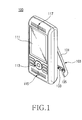
- FIG. 1 is a perspective view showing a portable terminal 100 including an antenna device according to a preferred embodiment of the present invention
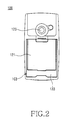
- FIG. 2 is a rear view showing the portable terminal 100 as shown in FIG. 1
- FIG. 3 is a perspective view showing the support 103 of the portable terminal 100 as shown in FIG. 1.
- a display device 111 and keypad 113 are disposed on the front surface of the portable terminal 100, a transmitter 115 is disposed at the bottom of the keypad 113, and a receiver 117 is disposed at the top of the display device 111. Additionally, a battery pack 121 is detachably mounted to the backside of the portable terminal 100, and a camera lens 123 is disposed at one side of the battery pack 121.
- the antenna device for general mobile communication of the portable terminal 100 is embedded therein and thus is not shown in the accompanying drawings.
- the antenna device embedded in the terminal 100 is set with a different frequency from one country to another, according to the communication modes supplied by service providers. In the case of U.S., frequency bands of 800 MHz and 1900 MHz are assigned to mobile communication servers.
- the portable terminal 100 is one capable of satellite or ground wave broadcasting service and includes a support 103, so as to maintain the terminal 100 fixed at a predetermined position when users enjoy DMB service.
- the support 103 includes a pair of pivotable links 131 and a connection plate 133.
- One end of each pivotable link 131 is pivotably, coupled to the terminal 100.
- a pivotable protrusion 139 is formed inside the end of the pivotable link 131, so as to be rotatably coupled to the terminal 100.
- the connection plate 133 connects remaining ends of the pivotable links 131, thereby ensuring structural stability of the support 103.
- a pair of slits (not shown) is formed along the longitudinal direction so that the pivotable links 131 can be received in the slits by pivoting on the terminal 100.
- the connection plate 133 is in close contact with the backside of the terminal 100.
- the pivotable links 131 can be pivotably coupled to the terminal 100 through the battery pack 121.
- each of the pivotable protrusions 139 disposed at one end of each pivotable link 131 can be pivotably coupled to both sides of the battery pack 121.
- the slits receiving the pivotable links 131 are formed between the housing of the terminal 100 and both lateral surfaces of the battery pack 121, so that the connection plate 133 can be in close contact with the outer surface of the battery pack 121.
- the portable terminal 100 is provided with a separate antenna module 135, operating in a frequency band of 180-186 MHz or 204-210 MHz for the purpose of satellite or ground wave DMB service.
- the antenna module 135 is disposed on the support 103 and connected to a Radio Frequency (RF) board (not shown) of the terminal 100 through the pivotable protrusions 139.
- RF Radio Frequency
- Various types of antenna modules 135 may be disposed on the support 103.
- the antenna module 135, as shown in FIGs. 1 and 3 has an antenna pattern including a conductive material applied to the inner surface of the support 103, particularly to the inner surface of the connection plate 133.
- the above antenna pattern is advantageous in that it can be modified into various forms so as to conform to characteristics of the antenna device required for the terminal 100.
- the antenna module 135 When mounting the antenna module 135 on the support 103, the antenna module 135 preferably takes any one form selected from a meander line antenna and loop antenna. A different form of antenna module can be mounted in addition to the meander line antenna and loop antenna, as long as the antenna module can utilize the space provided by the support 103 or connection plate 133.
- the antenna for DMB service may include an antenna module formed by manufacturing the support 103 itself with a conductive material instead of the antenna module 135 being disposed on the support 103.
- the support 103 serves as an antenna module as described above, there is a possibility of an electric shock caused by electric current leakage through the support 103. Therefore, it is preferable that the support 103 is coated with an insulation material.
- the support 103 itself serves as an antenna module, it is required that a part of the pivotable links 131, or a part of the pivotable links 131 and connection plate 133, be made of a conductive material, so that antenna characteristics required for the terminal can be ensured.
- the antenna device using a support for a portable terminal according to the present invention receives signals through the support when a user wants to enjoy DMB service.
- the support is provided in the terminal to avoid a need for a separate portable antenna for DMB service, thereby improving convenience of use.
- the terminal when the support is unfolded from the terminal, the terminal can be placed on a planar surface at a convenient angle for viewing, so that users can enjoy DMB service from a comfortable position.
Landscapes
- Engineering & Computer Science (AREA)
- Computer Networks & Wireless Communication (AREA)
- Telephone Set Structure (AREA)
- Support Of Aerials (AREA)
Applications Claiming Priority (1)
| Application Number | Priority Date | Filing Date | Title |
|---|---|---|---|
| KR20050061640 | 2005-07-08 |
Publications (1)
| Publication Number | Publication Date |
|---|---|
| EP1758201A2 true EP1758201A2 (fr) | 2007-02-28 |
Family
ID=37177799
Family Applications (1)
| Application Number | Title | Priority Date | Filing Date |
|---|---|---|---|
| EP06014257A Withdrawn EP1758201A2 (fr) | 2005-07-08 | 2006-07-10 | Antenne sur un support pour terminal portatif |
Country Status (3)
| Country | Link |
|---|---|
| US (1) | US20070008231A1 (fr) |
| EP (1) | EP1758201A2 (fr) |
| CN (1) | CN1893176A (fr) |
Families Citing this family (7)
| Publication number | Priority date | Publication date | Assignee | Title |
|---|---|---|---|---|
| CN101242023B (zh) * | 2007-02-09 | 2011-11-16 | 富士康(昆山)电脑接插件有限公司 | 数字电视天线 |
| KR20100096878A (ko) * | 2009-02-25 | 2010-09-02 | (주)엘티엠에이피 | 휴대통신단말기용 팝업 스탠드 조립체 |
| WO2010125763A1 (fr) * | 2009-04-28 | 2010-11-04 | パナソニック株式会社 | Récepteur |
| CN104752811B (zh) * | 2013-12-30 | 2019-03-29 | 联想(北京)有限公司 | 天线及无线接收电路 |
| CN103762410A (zh) * | 2014-01-13 | 2014-04-30 | 联想(北京)有限公司 | 一种电子设备 |
| JP2022007722A (ja) * | 2020-06-26 | 2022-01-13 | ソニーグループ株式会社 | 送受信機 |
| CN115939730A (zh) * | 2022-11-23 | 2023-04-07 | 上海祥承通讯技术有限公司 | 一种将背带扣作为nfc天线的手持电子设备 |
Family Cites Families (1)
| Publication number | Priority date | Publication date | Assignee | Title |
|---|---|---|---|---|
| US2388567A (en) * | 1943-01-28 | 1945-11-06 | Philco Radio & Television Corp | Portable radio receiver |
-
2006
- 2006-07-10 CN CNA2006101017880A patent/CN1893176A/zh active Pending
- 2006-07-10 EP EP06014257A patent/EP1758201A2/fr not_active Withdrawn
- 2006-07-10 US US11/483,884 patent/US20070008231A1/en not_active Abandoned
Also Published As
| Publication number | Publication date |
|---|---|
| CN1893176A (zh) | 2007-01-10 |
| US20070008231A1 (en) | 2007-01-11 |
Similar Documents
| Publication | Publication Date | Title |
|---|---|---|
| US7787922B2 (en) | Portable telephone with broadcast receiver | |
| US7512413B2 (en) | Systems and methods that employ multiple antennas with a device for mobile communication | |
| CN101809878B (zh) | 无线电设备 | |
| WO2011128738A1 (fr) | Dispositif de communication sans fil avec élément de boîtier qui fonctionne comme élément rayonnant d'une antenne | |
| CN100586033C (zh) | 具有广播接收机的便携式电话 | |
| US7339534B2 (en) | Antenna apparatus for a portable terminal | |
| EP1737066B1 (fr) | Dispositif d'antenne pour un terminal portable | |
| EP1758201A2 (fr) | Antenne sur un support pour terminal portatif | |
| CN101325281A (zh) | 用于移动电话的多波段天线 | |
| KR20090079720A (ko) | 외장 케이스 일체형 방송 수신용 안테나를 구비한 휴대용단말기 | |
| US7609214B2 (en) | Antenna assembly for portable terminal | |
| CN100449865C (zh) | 用于移动终端的可变天线装置 | |
| JPWO2011135851A1 (ja) | 無線端末 | |
| KR100762674B1 (ko) | 휴대용 단말기 | |
| KR100744281B1 (ko) | 휴대용 단말기의 안테나 장치 | |
| KR100663518B1 (ko) | 휴대 단말기의 안테나 스위치 장치 | |
| KR100677393B1 (ko) | 안테나를 구비한 휴대용 단말기 | |
| US20060279466A1 (en) | Antenna apparatus for portable terminal | |
| KR100713453B1 (ko) | 휴대용 단말기용 디지털 멀티미디어 방송 모듈의 안테나장치 | |
| KR100802616B1 (ko) | 휴대 단말기 | |
| KR20070052255A (ko) | 휴대용 단말기의 안테나 장치 | |
| KR20090112913A (ko) | 휴대용 단말기의 안테나 장치 | |
| KR20100014030A (ko) | 휴대 단말기 | |
| JP2003283625A (ja) | 情報通信機器 |
Legal Events
| Date | Code | Title | Description |
|---|---|---|---|
| PUAI | Public reference made under article 153(3) epc to a published international application that has entered the european phase |
Free format text: ORIGINAL CODE: 0009012 |
|
| 17P | Request for examination filed |
Effective date: 20060710 |
|
| AK | Designated contracting states |
Kind code of ref document: A2 Designated state(s): AT BE BG CH CY CZ DE DK EE ES FI FR GB GR HU IE IS IT LI LT LU LV MC NL PL PT RO SE SI SK TR |
|
| AX | Request for extension of the european patent |
Extension state: AL BA HR MK YU |
|
| STAA | Information on the status of an ep patent application or granted ep patent |
Free format text: STATUS: THE APPLICATION HAS BEEN WITHDRAWN |
|
| 18W | Application withdrawn |
Effective date: 20080125 |