EP1759092B1 - Dispositif de detection d'une rupture d'arbre sur une turbine a gaz et turbine a gaz - Google Patents
Dispositif de detection d'une rupture d'arbre sur une turbine a gaz et turbine a gaz Download PDFInfo
- Publication number
- EP1759092B1 EP1759092B1 EP05759102A EP05759102A EP1759092B1 EP 1759092 B1 EP1759092 B1 EP 1759092B1 EP 05759102 A EP05759102 A EP 05759102A EP 05759102 A EP05759102 A EP 05759102A EP 1759092 B1 EP1759092 B1 EP 1759092B1
- Authority
- EP
- European Patent Office
- Prior art keywords
- turbine
- gas turbine
- pressure turbine
- shaft
- pressure
- Prior art date
- Legal status (The legal status is an assumption and is not a legal conclusion. Google has not performed a legal analysis and makes no representation as to the accuracy of the status listed.)
- Ceased
Links
- 230000005540 biological transmission Effects 0.000 claims description 22
- 238000002485 combustion reaction Methods 0.000 claims description 6
- 238000007789 sealing Methods 0.000 claims description 2
- 238000006073 displacement reaction Methods 0.000 description 4
- 238000011144 upstream manufacturing Methods 0.000 description 4
- 230000000712 assembly Effects 0.000 description 3
- 238000000429 assembly Methods 0.000 description 3
- 238000001514 detection method Methods 0.000 description 3
- 239000000446 fuel Substances 0.000 description 3
- 239000012530 fluid Substances 0.000 description 2
- 238000012423 maintenance Methods 0.000 description 2
- 230000009347 mechanical transmission Effects 0.000 description 2
- 230000001419 dependent effect Effects 0.000 description 1
Images
Classifications
-
- F—MECHANICAL ENGINEERING; LIGHTING; HEATING; WEAPONS; BLASTING
- F01—MACHINES OR ENGINES IN GENERAL; ENGINE PLANTS IN GENERAL; STEAM ENGINES
- F01D—NON-POSITIVE DISPLACEMENT MACHINES OR ENGINES, e.g. STEAM TURBINES
- F01D21/00—Shutting-down of machines or engines, e.g. in emergency; Regulating, controlling, or safety means not otherwise provided for
- F01D21/04—Shutting-down of machines or engines, e.g. in emergency; Regulating, controlling, or safety means not otherwise provided for responsive to undesired position of rotor relative to stator or to breaking-off of a part of the rotor, e.g. indicating such position
- F01D21/045—Shutting-down of machines or engines, e.g. in emergency; Regulating, controlling, or safety means not otherwise provided for responsive to undesired position of rotor relative to stator or to breaking-off of a part of the rotor, e.g. indicating such position special arrangements in stators or in rotors dealing with breaking-off of part of rotor
-
- F—MECHANICAL ENGINEERING; LIGHTING; HEATING; WEAPONS; BLASTING
- F02—COMBUSTION ENGINES; HOT-GAS OR COMBUSTION-PRODUCT ENGINE PLANTS
- F02C—GAS-TURBINE PLANTS; AIR INTAKES FOR JET-PROPULSION PLANTS; CONTROLLING FUEL SUPPLY IN AIR-BREATHING JET-PROPULSION PLANTS
- F02C9/00—Controlling gas-turbine plants; Controlling fuel supply in air- breathing jet-propulsion plants
- F02C9/26—Control of fuel supply
- F02C9/46—Emergency fuel control
-
- F—MECHANICAL ENGINEERING; LIGHTING; HEATING; WEAPONS; BLASTING
- F05—INDEXING SCHEMES RELATING TO ENGINES OR PUMPS IN VARIOUS SUBCLASSES OF CLASSES F01-F04
- F05D—INDEXING SCHEME FOR ASPECTS RELATING TO NON-POSITIVE-DISPLACEMENT MACHINES OR ENGINES, GAS-TURBINES OR JET-PROPULSION PLANTS
- F05D2270/00—Control
- F05D2270/01—Purpose of the control system
- F05D2270/02—Purpose of the control system to control rotational speed (n)
- F05D2270/021—Purpose of the control system to control rotational speed (n) to prevent overspeed
-
- F—MECHANICAL ENGINEERING; LIGHTING; HEATING; WEAPONS; BLASTING
- F05—INDEXING SCHEMES RELATING TO ENGINES OR PUMPS IN VARIOUS SUBCLASSES OF CLASSES F01-F04
- F05D—INDEXING SCHEME FOR ASPECTS RELATING TO NON-POSITIVE-DISPLACEMENT MACHINES OR ENGINES, GAS-TURBINES OR JET-PROPULSION PLANTS
- F05D2270/00—Control
- F05D2270/01—Purpose of the control system
- F05D2270/09—Purpose of the control system to cope with emergencies
Definitions
- the invention relates to a gas turbine with a device for detecting a shaft fracture, according to the preamble of patent claim 1.
- Gas turbines designed as aircraft engines have at least one compressor, at least one combustion chamber and at least one turbine.
- Aircraft engines are known from the prior art, on the one hand have three upstream of the combustion chamber positioned compressor and three positioned downstream of the combustion chamber turbines.
- the three compressors are a low-pressure compressor, a medium-pressure compressor and a high-pressure compressor.
- the three turbines are a high-pressure turbine, a medium-pressure turbine and a low-pressure turbine.
- the rotors of high-pressure compressor and high-pressure turbine, medium-pressure compressor and medium-pressure turbine and low-pressure compressor and low-pressure turbine are connected by a respective shaft, wherein the three shafts surround each other concentrically and are thus interleaved.
- the medium pressure compressor and the intermediate pressure turbine interconnect shaft so the medium pressure compressor of the medium-pressure turbine can no longer refer to work, which then can set an overspeed on the medium-pressure turbine.
- spin-off of the medium-pressure turbine must be avoided, as this can damage the entire aircraft engine.
- a shaft break on a gas turbine must be reliably detectable in order to interrupt a fuel supply to the combustion chamber when a shaft fracture occurs.
- Such a detection of a wave fracture is particularly difficult if the gas turbine, as described above, has three concentrically enclosing and thus nested waves. In this case, especially the detection of a shaft breakage of the middle wave, which couples the intermediate-pressure turbine with the medium-pressure compressor, presents difficulties.
- JP 03121219 A relates to a device for detecting a shaft fracture on a gas turbine, in which a line filled with an incompressible fluid extends into the region of the end of a turbine shaft.
- a line filled with an incompressible fluid extends into the region of the end of a turbine shaft.
- the present invention is based on the problem of proposing a gas turbine with a novel device for detecting a shaft break, which makes it possible to safely detect a shaft break in the interior of a multi-shaft, difficult to access turbine assembly.
- a gas turbine with a device for detecting a shaft breakage serves to detect a shaft fracture on a rotor of a first turbine, in particular of a medium-pressure turbine, wherein a second turbine, in particular a low-pressure turbine, is positioned downstream of the first turbine.
- the device has an actuator positioned radially inward between the rotor of the first turbine and a stator of the second turbine, adjacent to a downstream rotor disk of the first turbine, axially displaceable in the stator of the second turbine, and radially guided in the stator of the second turbine Transmission element to transmit a detected by the radially inwardly positioned actuator shaft break to a switching element, which is positioned opposite the flow channel radially outboard on a housing of the gas turbine.
- a gas turbine with a device for detecting a shaft break which has a radially inwardly positioned, mechanical actuating element for the mechanical detection of a shaft fracture, and a mechanical transmission element for the mechanical transmission of the shaft element detected by the actuating element to a radially outward switching element, wherein between the actuating element and the transmission element and / or between the transmission element Ü and the switching element, an elastically deformable spring element is arranged.
- the switching element is mounted radially on the outside of a housing of the gas turbine.
- the switching element which communicates with the control electronics of the aircraft engine and is designed as an electrical or electronic switching element, is easily accessible radially outwardly attached to the housing of the gas turbine.
- the switching element is therefore easily accessible for maintenance.
- FIG Fig. 1 described in more detail.
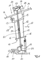
- Fig. 1 shows a partial cross-section through a gas turbine according to the invention, namely an aircraft engine, in the region of a stator vane ring 10 of a low-pressure turbine 11.
- the in Fig. 1 illustrated vane ring 10 of the low-pressure turbine 11 is formed by a plurality of circumferentially spaced, stationary vanes 12, wherein the guide vanes 12 are fixed with a radially outer portion 13 on a stator housing 14 of the gas turbine.
- Blade blades 15 of the guide vanes 12 of the vane ring 10 extend in the radial direction between the radially outer portion 13 and a radially inner portion 16 of the vanes 12 in the region of a flow channel of the low-pressure turbine eleventh
- Fig. 1 The flow direction through the flow channel is in Fig. 1 visualized by arrows 17.
- vane ring 10 of the low-pressure turbine 11 is in the flow direction (arrow 17) seen first vane ring of the low-pressure turbine 11. Downstream of this vane ring 10, a non-illustrated blade ring of the low-pressure turbine 11 is positioned. Upstream of the low-pressure turbine 11, a non-illustrated medium-pressure turbine is arranged. It borders on the in Fig. 1 shown, seen in the flow direction first vane ring 10 of the low-pressure turbine 11 a last seen in the flow direction, not shown blade ring of the intermediate-pressure turbine. Upstream of the medium-pressure turbine, a high-pressure turbine is preferably positioned.
- an actuator 18 between the rotor of the non-illustrated medium-pressure turbine and the stator of the low-pressure turbine 11, wherein the actuator 18 in the embodiment shown between the last seen in the flow direction of the rotor blade ring of the intermediate-pressure turbine and in the flow direction first vane ring 10 of the low-pressure turbine 11 is positioned.
- the actuating element 18 is positioned radially inwardly relative to the flow channel inside the gas turbine to a non-illustrated rotor disk of the last rotor blade ring of the intermediate-pressure turbine (not shown).
- the actuating element 18 is displaceably guided in a flow direction or in the axial direction in a radially inner sealing structure 19 of the stator of the low-pressure turbine 11.
- the axial displaceability of the actuating element 18 is in Fig. 1 illustrated by a double arrow 20. As Fig. 1 can be removed, engages an elastically deformable spring element 21 at one end of the actuating element 18, the curvature of which depends directly on the axial position of the actuating element 18.
- the rotor of the medium-pressure turbine due to the pressure differences within the medium-pressure turbine in the direction of the stator of the low-pressure turbine 11 and thus to the rear or in the flow direction (arrow 17) moves in that the rotor of the medium-pressure turbine touches the actuating element 18 and moves in the axial direction in the direction of the arrows 17.
- the rotor disk of the last rotor blade ring of the medium-pressure turbine viewed in the direction of flow, actuates the actuating element 18 assigned to the first guide blade ring 10 of the low-pressure turbine 11, viewed in the flow direction.
- the actuating element 18 cooperates with a transmission element 22 in order to transmit a shaft break detected by the actuating element 18 to a switching element 23 which extends radially outward from the housing 14 Gas turbine is attached.
- a transmission element 22 in the stator of the low-pressure turbine 11 namely in the stator-side guide vane ring 10 of the low-pressure turbine 11, guided displaceably in the radial direction.
- the radial displaceability of the transmission element 22 is in Fig. 1 visualized by a double arrow 24.
- the transmission element 22 extends in the radial direction through the in Fig. 1 shown guide vane 12 of the vane ring 10, wherein the transmission element cooperates at a radially inner end 25 with the actuating element 18 and a radially outer end 26 with the switching element 23. If the rotor of the medium-pressure turbine is moved in the direction of the arrows 17 in the case of a shaft break in the area of the medium-pressure system of the gas turbine and the actuating element 18 is also axially displaced in the direction of the arrows 17, a stronger bulge of the spring element 21 occurs, as a result of which the transmission element 22 is in the radial direction Direction is shifted outwards.
- the radially outer end 26 of the transmission element 22 cooperates with a spring element 27, which in a caused by a shaft break, radially outward displacement of the transmission element 22 of the in Fig. 1 position shown by solid lines in the in Fig. 1 Position shown with dashed lines is deformed and ultimately the switching element 23 is actuated.
- the switching element 23 is connected to a module 28 of a control device of the gas turbine, which interrupts a fuel supply to the combustion chamber of the gas turbine at a detected shaft break.
- a device for detecting a shaft fracture on a gas turbine in which a shaft break is detected with a radially inner actuating element 18 in a mechanical manner, and with a transmission element 22 the shaft break detected by the actuating element 18 mechanical manner to a radially outside of the housing 14 of the gas turbine positioned switching element 23 is transmitted.
- Radially internal or difficult to access assemblies of the device according to the invention for detecting a shaft break are based on a purely mechanical action principle and are therefore very robust. Electrical or electronic assemblies of the device according to the invention, such as the switching element 23 and the module 28, are only externally attached to the housing 14 of the gas turbine and thus easily accessible for maintenance.
- Fig. 1 acts the transmission element 22 at the radially inner end 25 via a spring element 21 with the actuating element 18 and dam radially outer end 26 via the spring element 27 with the switching element 23 together.
- the transmission element 22 can interact directly with the actuating element 18 or the switching element 23.
- the actuating element 18 at a portion on which it cooperates with the transmission element 22 have a conical portion to a axial displacement of the actuating element 18 in the direction of the double arrow 20, a radial displacement of the transmission element 22 in the direction of the double arrow 24th to ensure.
- the spring element 24 is preferably designed as a snap spring plate. As a result, in the case of a shaft break, the radially outward displacement of the transmission element 22 is emphasized and converted into a permanent snap-fitting of the diaphragm spring. This increases safety in the operation of the switching element 23.
Landscapes
- Engineering & Computer Science (AREA)
- Mechanical Engineering (AREA)
- General Engineering & Computer Science (AREA)
- Chemical & Material Sciences (AREA)
- Combustion & Propulsion (AREA)
- Control Of Turbines (AREA)
- Measuring Fluid Pressure (AREA)
- Turbine Rotor Nozzle Sealing (AREA)
Claims (2)
- Turbine à gaz, en particulier turboréacteur, comportant au moins deux compresseurs, au moins une chambre de combustion et au moins deux turbines, et comportant un dispositif de détection d'une rupture d'arbre au niveau d'un rotor d'une première turbine, en particulier d'une turbine moyenne pression, une deuxième turbine (11), en particulier une turbine basse pression, étant positionnée en aval de la première turbine, caractérisée en ce qu'un élément d'actionnement (18) est positionné entre le rotor de la première turbine et un stator de la deuxième turbine (11) radialement à l'intérieur et de manière adjacente à un disque de rotor de la dernière couronne d'aubes mobiles, vue dans le sens d'écoulement, de la première turbine et guidé de manière coulissante en direction axiale et/ou dans le sens d'écoulement dans une structure d'étanchéification (19), située radialement à l'intérieur, du stator de la deuxième turbine (11), en ce qu'un élément de transmission (22) est guidé de manière coulissante en direction radiale dans le stator de la deuxième turbine (11), en ce que l'élément de transmission (22) interagit au niveau d'une extrémité (25) située radialement à l'intérieur avec l'élément d'actionnement (18) et au niveau d'une extrémité (26) située radialement à l'extérieur avec un élément de commutation (23) positionné radialement à l'extérieur au niveau d'un carter (14) de la turbine à gaz pour transmettre une rupture d'arbre détectée par l'élément d'actionnement (18) au niveau de l'élément de commutation (23) et en ce qu'un élément formant ressort (21, 27) à déformation élastique est disposé entre l'élément d'actionnement (18) et l'élément de transmission (22) et/ou entre l'élément de transmission (22) et l'élément de commutation (23).
- Turbine à gaz selon la revendication 1, caractérisée en ce que l'élément de transmission (22) est guidé dans une première couronne d'aubes fixes (10), vue dans le sens d'écoulement, de la deuxième turbine (11).
Applications Claiming Priority (2)
| Application Number | Priority Date | Filing Date | Title |
|---|---|---|---|
| DE102004026366A DE102004026366A1 (de) | 2004-05-29 | 2004-05-29 | Einrichtung zur Detektion eines Wellenbruchs an einer Gasturbine sowie Gasturbine |
| PCT/DE2005/001042 WO2005116406A1 (fr) | 2004-05-29 | 2005-05-20 | Dispositif de detection d'une rupture d'arbre sur une turbine a gaz et turbine a gaz |
Publications (2)
| Publication Number | Publication Date |
|---|---|
| EP1759092A1 EP1759092A1 (fr) | 2007-03-07 |
| EP1759092B1 true EP1759092B1 (fr) | 2008-04-30 |
Family
ID=34971995
Family Applications (1)
| Application Number | Title | Priority Date | Filing Date |
|---|---|---|---|
| EP05759102A Ceased EP1759092B1 (fr) | 2004-05-29 | 2005-05-20 | Dispositif de detection d'une rupture d'arbre sur une turbine a gaz et turbine a gaz |
Country Status (6)
| Country | Link |
|---|---|
| US (1) | US7780400B2 (fr) |
| EP (1) | EP1759092B1 (fr) |
| DE (2) | DE102004026366A1 (fr) |
| RU (1) | RU2374460C2 (fr) |
| UA (1) | UA83937C2 (fr) |
| WO (1) | WO2005116406A1 (fr) |
Families Citing this family (12)
| Publication number | Priority date | Publication date | Assignee | Title |
|---|---|---|---|---|
| DE102004033924A1 (de) * | 2004-07-14 | 2006-02-09 | Mtu Aero Engines Gmbh | Einrichtung zur Detektion eines Wellenbruchs an einer Gasturbine sowie Gasturbine |
| DE102006017790B3 (de) * | 2006-04-15 | 2007-07-26 | Mtu Aero Engines Gmbh | Einrichtung zur Detektion eines Wellenbruchs an einer Gasturbine sowie Gasturbine |
| KR100954157B1 (ko) * | 2007-12-21 | 2010-04-20 | 한국항공우주연구원 | 터보기계 블레이드 파손 모니터링 유닛 및 이를 갖는 터보장치 |
| US9355571B2 (en) * | 2008-01-23 | 2016-05-31 | Sikorsky Aircraft Corporation | Modules and methods for biasing power to a multi-engine power plant suitable for one engine inoperative flight procedure training |
| GB2468686A (en) * | 2009-03-18 | 2010-09-22 | Weston Aerospace Ltd | System and method for detecting abnormal movement in a gas turbine shaft |
| US9169742B2 (en) * | 2010-02-26 | 2015-10-27 | Pratt & Whitney Canada Corp. | Electronic shaft shear detection conditioning circuit |
| US8864446B2 (en) * | 2011-05-23 | 2014-10-21 | Siemens Energy, Inc. | Wear pin gap closure detection system for gas turbine engine |
| WO2016118659A1 (fr) | 2015-01-20 | 2016-07-28 | 360 Yield Center, Llc | Appareil et procédé de gestion de résidus de moisson |
| US10190440B2 (en) | 2015-06-10 | 2019-01-29 | Rolls-Royce North American Technologies, Inc. | Emergency shut-down detection system for a gas turbine |
| FR3075863B1 (fr) * | 2017-12-22 | 2019-11-22 | Safran Aircraft Engines | Turbine de turbomachine comportant un dispositif de limitation de survitesse |
| DE102018126930B4 (de) * | 2018-10-29 | 2023-05-17 | Rolls-Royce Deutschland Ltd & Co Kg | Verstellvorrichtung und ein Verfahren zur Verstellung der Leitschaufeln eines Verdichters eines Gasturbinentriebwerks |
| US11504813B2 (en) | 2020-05-18 | 2022-11-22 | Rolls-Royce Plc | Methods for health monitoring of ceramic matrix composite components in gas turbine engines |
Family Cites Families (32)
| Publication number | Priority date | Publication date | Assignee | Title |
|---|---|---|---|---|
| US2815818A (en) | 1957-12-10 | Certificate of correction | ||
| US1326867A (en) | 1918-12-06 | 1919-12-30 | Gen Electric | Elastic-fluid turbine. |
| US2977758A (en) | 1955-02-18 | 1961-04-04 | Rolls Royce | Propeller driving gas-turbine engines |
| GB903945A (en) * | 1957-10-29 | 1962-08-22 | Rolls Royce | Improvements in or relating to gas-turbine engines |
| GB982292A (en) * | 1960-06-30 | 1965-02-03 | Fairfield Shipbuilding & Engin | Trip gear for turbines |
| US3159166A (en) | 1961-10-16 | 1964-12-01 | Gen Motors Corp | Engine safety control |
| DE1915930B2 (de) | 1968-04-03 | 1971-06-09 | Motoren und Turbinen Union München GmbH, 8000 München | Vorrichtung an tirbomaschinen zum fruehzeitigen erkennen von schaufelschaeden |
| DE2062047A1 (de) | 1970-12-16 | 1972-07-06 | Motoren Turbinen Union | Warnvorrichtung |
| US3696612A (en) | 1970-12-30 | 1972-10-10 | Westinghouse Electric Corp | Fuel pump system for gas turbines |
| GB1443333A (en) | 1972-08-12 | 1976-07-21 | Mtu Muenchen Gmbh | Aircraft having apparatus for augmenting the lift of the aircraft |
| US3989408A (en) | 1974-05-20 | 1976-11-02 | Westinghouse Electric Corporation | Positioning device for a turbine rotor position sensor |
| JPS5274737A (en) | 1975-12-19 | 1977-06-23 | Hitachi Ltd | Operation stopper of hydraulical machinery |
| GB2002857A (en) * | 1977-08-16 | 1979-02-28 | Rolls Royce | Means for detecting relative movement between parts of machines |
| US4406117A (en) | 1979-10-26 | 1983-09-27 | General Electric Company | Cyclic load duty control for gas turbine |
| GB2124788B (en) * | 1982-06-30 | 1986-05-21 | Rolls Royce | Torque-sensitive control of gas turbines |
| US4498291A (en) | 1982-10-06 | 1985-02-12 | Rolls-Royce Limited | Turbine overspeed limiter for turbomachines |
| JPH03121219A (ja) * | 1989-10-03 | 1991-05-23 | Mitsubishi Heavy Ind Ltd | エンジンの緊急停止装置 |
| US5301499A (en) | 1990-06-28 | 1994-04-12 | General Electric Company | Overspeed anticipation and control system for single shaft combined cycle gas and steam turbine unit |
| US5363317A (en) * | 1992-10-29 | 1994-11-08 | United Technologies Corporation | Engine failure monitor for a multi-engine aircraft having partial engine failure and driveshaft failure detection |
| RU2086779C1 (ru) * | 1993-10-21 | 1997-08-10 | Омское моторостроительное конструкторское бюро | Устройство защиты газотурбинного двигателя |
| US5411364A (en) | 1993-12-22 | 1995-05-02 | Allied-Signal Inc. | Gas turbine engine failure detection system |
| DE19524992C1 (de) | 1995-07-08 | 1996-08-08 | Mtu Muenchen Gmbh | Regelung eines Wellentriebwerks mit einem Mikrosteuergerät |
| DE19727296A1 (de) | 1997-06-27 | 1999-01-07 | Mtu Muenchen Gmbh | Einrichtung zur Notabschaltung einer Gasturbine |
| DE19857552A1 (de) | 1998-12-14 | 2000-06-15 | Rolls Royce Deutschland | Verfahren zum Erkennen eines Wellenbruches in einer Strömungskraftmaschine |
| US6546735B1 (en) | 2001-03-07 | 2003-04-15 | General Electric Company | Methods and apparatus for operating turbine engines using rotor temperature sensors |
| RU2187008C1 (ru) * | 2001-05-16 | 2002-08-10 | Общевойсковая Академия Вооруженных Сил Российской Федерации | Устройство для предохранения от поломок силовой турбины газотурбинного двигателя |
| US6607349B2 (en) * | 2001-11-14 | 2003-08-19 | Honeywell International, Inc. | Gas turbine engine broken shaft detection system |
| DE10310900A1 (de) | 2003-03-13 | 2004-09-23 | Rolls-Royce Deutschland Ltd & Co Kg | Elekronisches Sicherheitssystem zur Vermeidung eines Überdrehzahlzustandes bei einem Wellenbruch |
| US7043896B2 (en) | 2003-11-21 | 2006-05-16 | Pratt & Whitney Canada Corp. | Method and apparatus for controlling fuel flow to an engine |
| DE102004033924A1 (de) | 2004-07-14 | 2006-02-09 | Mtu Aero Engines Gmbh | Einrichtung zur Detektion eines Wellenbruchs an einer Gasturbine sowie Gasturbine |
| DE102004047892A1 (de) | 2004-10-01 | 2006-04-06 | Mtu Aero Engines Gmbh | Gasturbine und Verfahren zum Abschalten einer Gasturbine bei Identifikation eines Wellenbruchs |
| US7207768B2 (en) | 2005-01-15 | 2007-04-24 | Siemens Power Generation, Inc. | Warning system for turbine component contact |
-
2004
- 2004-05-29 DE DE102004026366A patent/DE102004026366A1/de not_active Withdrawn
-
2005
- 2005-05-20 DE DE502005003913T patent/DE502005003913D1/de not_active Expired - Lifetime
- 2005-05-20 RU RU2006145058/06A patent/RU2374460C2/ru not_active IP Right Cessation
- 2005-05-20 UA UAA200613526A patent/UA83937C2/ru unknown
- 2005-05-20 WO PCT/DE2005/001042 patent/WO2005116406A1/fr not_active Ceased
- 2005-05-20 EP EP05759102A patent/EP1759092B1/fr not_active Ceased
- 2005-05-20 US US11/628,025 patent/US7780400B2/en not_active Expired - Fee Related
Also Published As
| Publication number | Publication date |
|---|---|
| UA83937C2 (ru) | 2008-08-26 |
| DE502005003913D1 (de) | 2008-06-12 |
| US7780400B2 (en) | 2010-08-24 |
| DE102004026366A1 (de) | 2005-12-15 |
| WO2005116406A1 (fr) | 2005-12-08 |
| US20080069685A1 (en) | 2008-03-20 |
| EP1759092A1 (fr) | 2007-03-07 |
| RU2374460C2 (ru) | 2009-11-27 |
| RU2006145058A (ru) | 2008-07-10 |
Similar Documents
| Publication | Publication Date | Title |
|---|---|---|
| EP1759092B1 (fr) | Dispositif de detection d'une rupture d'arbre sur une turbine a gaz et turbine a gaz | |
| DE60217365T2 (de) | Dichtungsverfahren und vorichtung für die welle einer gasturbine | |
| DE602004002049T2 (de) | Niederdruck-Turbine einer Turbomaschine | |
| EP1664490B1 (fr) | Dispositif pour detecter une rupture d'arbre sur une turbine a gaz et turbine a gaz | |
| WO2005078242A1 (fr) | Systeme amortisseur pour aubes directrices | |
| CH708854A2 (de) | Ansaugflächendichtung einer Rotationsmaschine und Verfahren zur Montage derselben. | |
| EP2884054A1 (fr) | Aube de guidage variable avec cône tronqué dans un ensemble palier | |
| WO2010091956A1 (fr) | Turbocompresseur axial pour une turbine à gaz avec faibles pertes par les fentes radiales et les diffuseurs | |
| WO2001031169A1 (fr) | Dispositif pour compenser la poussee axiale dans des turbomachines | |
| DE102013213386B3 (de) | Strömungsmaschinen-Keramikbauteil | |
| DE102007050916A1 (de) | Verfahren und Vorrichtung zum Zusammenbau von Gasturbinen-Triebwerken | |
| EP0806547A1 (fr) | Turbine axiale pour turbocompresseurs | |
| EP2129875B1 (fr) | Turbomachine avec controle de jeu actif | |
| EP1625304B1 (fr) | Pompe centrifuge multi-etagee | |
| WO2007051443A1 (fr) | Turbomoteur dote d'un tirant d'ancrage constitue de douilles de traction et de poussee | |
| DE102010036071A1 (de) | Gehäuseseitige Struktur einer Turbomaschine | |
| EP1922472B1 (fr) | Turbine a gaz pourvue d'un dispositif de detection d'une rupture de l'arbre | |
| DE102019204507A1 (de) | Gleitlagervorrichtung, ein Verfahren zum Betrieb einer Gleitlagervorrichtung und ein Gasturbinentriebwerk | |
| EP2770191A2 (fr) | Turbine à gaz d'aéronef dotée d'un premier arbre rotatif | |
| EP3392463A1 (fr) | Turbomachine | |
| EP3330494B1 (fr) | Dispositif, turbomachine et procédé de détection d'une rupture d'arbre | |
| DE102019214673A1 (de) | Statorbaugruppe, Vormontagemodul und Montageverfahren | |
| DE102006017790B3 (de) | Einrichtung zur Detektion eines Wellenbruchs an einer Gasturbine sowie Gasturbine | |
| EP3133263B1 (fr) | Cartouche de rotor pour une turbomachine d'un moteur à combustion interne, turbomachine d'un moteur à combustion interne et procédé de montage d'une turbomachine d'un moteur à combustion interne | |
| CH714650A2 (de) | Radialverdichter. |
Legal Events
| Date | Code | Title | Description |
|---|---|---|---|
| PUAI | Public reference made under article 153(3) epc to a published international application that has entered the european phase |
Free format text: ORIGINAL CODE: 0009012 |
|
| 17P | Request for examination filed |
Effective date: 20061215 |
|
| AK | Designated contracting states |
Kind code of ref document: A1 Designated state(s): DE FR GB |
|
| 17Q | First examination report despatched |
Effective date: 20070420 |
|
| RBV | Designated contracting states (corrected) |
Designated state(s): DE FR GB |
|
| DAX | Request for extension of the european patent (deleted) | ||
| GRAP | Despatch of communication of intention to grant a patent |
Free format text: ORIGINAL CODE: EPIDOSNIGR1 |
|
| GRAS | Grant fee paid |
Free format text: ORIGINAL CODE: EPIDOSNIGR3 |
|
| GRAA | (expected) grant |
Free format text: ORIGINAL CODE: 0009210 |
|
| AK | Designated contracting states |
Kind code of ref document: B1 Designated state(s): DE FR GB |
|
| REG | Reference to a national code |
Ref country code: GB Ref legal event code: FG4D Free format text: NOT ENGLISH |
|
| REF | Corresponds to: |
Ref document number: 502005003913 Country of ref document: DE Date of ref document: 20080612 Kind code of ref document: P |
|
| ET | Fr: translation filed | ||
| PLBE | No opposition filed within time limit |
Free format text: ORIGINAL CODE: 0009261 |
|
| STAA | Information on the status of an ep patent application or granted ep patent |
Free format text: STATUS: NO OPPOSITION FILED WITHIN TIME LIMIT |
|
| 26N | No opposition filed |
Effective date: 20090202 |
|
| REG | Reference to a national code |
Ref country code: GB Ref legal event code: 732E Free format text: REGISTERED BETWEEN 20131114 AND 20131120 |
|
| REG | Reference to a national code |
Ref country code: FR Ref legal event code: PLFP Year of fee payment: 12 |
|
| REG | Reference to a national code |
Ref country code: FR Ref legal event code: PLFP Year of fee payment: 13 |
|
| PGFP | Annual fee paid to national office [announced via postgrant information from national office to epo] |
Ref country code: GB Payment date: 20170524 Year of fee payment: 13 Ref country code: DE Payment date: 20170522 Year of fee payment: 13 Ref country code: FR Payment date: 20170522 Year of fee payment: 13 |
|
| REG | Reference to a national code |
Ref country code: DE Ref legal event code: R119 Ref document number: 502005003913 Country of ref document: DE |
|
| GBPC | Gb: european patent ceased through non-payment of renewal fee |
Effective date: 20180520 |
|
| PG25 | Lapsed in a contracting state [announced via postgrant information from national office to epo] |
Ref country code: FR Free format text: LAPSE BECAUSE OF NON-PAYMENT OF DUE FEES Effective date: 20180531 Ref country code: GB Free format text: LAPSE BECAUSE OF NON-PAYMENT OF DUE FEES Effective date: 20180520 Ref country code: DE Free format text: LAPSE BECAUSE OF NON-PAYMENT OF DUE FEES Effective date: 20181201 |