EP1759232B1 - Verfahren und installation zur herstellung eines gefaserten elements mit einem lichtselektiven filter - Google Patents
Verfahren und installation zur herstellung eines gefaserten elements mit einem lichtselektiven filter Download PDFInfo
- Publication number
- EP1759232B1 EP1759232B1 EP05752873A EP05752873A EP1759232B1 EP 1759232 B1 EP1759232 B1 EP 1759232B1 EP 05752873 A EP05752873 A EP 05752873A EP 05752873 A EP05752873 A EP 05752873A EP 1759232 B1 EP1759232 B1 EP 1759232B1
- Authority
- EP
- European Patent Office
- Prior art keywords
- assembly
- optical
- refractive index
- silica
- fibered
- Prior art date
- Legal status (The legal status is an assumption and is not a legal conclusion. Google has not performed a legal analysis and makes no representation as to the accuracy of the status listed.)
- Expired - Lifetime
Links
Images

Classifications
-
- G—PHYSICS
- G02—OPTICS
- G02B—OPTICAL ELEMENTS, SYSTEMS OR APPARATUS
- G02B6/00—Light guides; Structural details of arrangements comprising light guides and other optical elements, e.g. couplings
- G02B6/44—Mechanical structures for providing tensile strength and external protection for fibres, e.g. optical transmission cables
- G02B6/4479—Manufacturing methods of optical cables
- G02B6/4482—Code or colour marking
-
- C—CHEMISTRY; METALLURGY
- C03—GLASS; MINERAL OR SLAG WOOL
- C03B—MANUFACTURE, SHAPING, OR SUPPLEMENTARY PROCESSES
- C03B37/00—Manufacture or treatment of flakes, fibres, or filaments from softened glass, minerals, or slags
- C03B37/01—Manufacture of glass fibres or filaments
- C03B37/012—Manufacture of preforms for drawing fibres or filaments
- C03B37/0128—Manufacture of preforms for drawing fibres or filaments starting from pulverulent glass
- C03B37/01291—Manufacture of preforms for drawing fibres or filaments starting from pulverulent glass by progressive melting, e.g. melting glass powder during delivery to and adhering the so-formed melt to a target or preform, e.g. the Plasma Oxidation Deposition [POD] process
-
- C—CHEMISTRY; METALLURGY
- C03—GLASS; MINERAL OR SLAG WOOL
- C03C—CHEMICAL COMPOSITION OF GLASSES, GLAZES OR VITREOUS ENAMELS; SURFACE TREATMENT OF GLASS; SURFACE TREATMENT OF FIBRES OR FILAMENTS MADE FROM GLASS, MINERALS OR SLAGS; JOINING GLASS TO GLASS OR OTHER MATERIALS
- C03C13/00—Fibre or filament compositions
- C03C13/04—Fibre optics, e.g. core and clad fibre compositions
- C03C13/045—Silica-containing oxide glass compositions
- C03C13/046—Multicomponent glass compositions
-
- C—CHEMISTRY; METALLURGY
- C03—GLASS; MINERAL OR SLAG WOOL
- C03C—CHEMICAL COMPOSITION OF GLASSES, GLAZES OR VITREOUS ENAMELS; SURFACE TREATMENT OF GLASS; SURFACE TREATMENT OF FIBRES OR FILAMENTS MADE FROM GLASS, MINERALS OR SLAGS; JOINING GLASS TO GLASS OR OTHER MATERIALS
- C03C25/00—Surface treatment of fibres or filaments made from glass, minerals or slags
- C03C25/10—Coating
- C03C25/104—Coating to obtain optical fibres
- C03C25/105—Organic claddings
-
- C—CHEMISTRY; METALLURGY
- C03—GLASS; MINERAL OR SLAG WOOL
- C03C—CHEMICAL COMPOSITION OF GLASSES, GLAZES OR VITREOUS ENAMELS; SURFACE TREATMENT OF GLASS; SURFACE TREATMENT OF FIBRES OR FILAMENTS MADE FROM GLASS, MINERALS OR SLAGS; JOINING GLASS TO GLASS OR OTHER MATERIALS
- C03C25/00—Surface treatment of fibres or filaments made from glass, minerals or slags
- C03C25/10—Coating
- C03C25/465—Coatings containing composite materials
- C03C25/475—Coatings containing composite materials containing colouring agents
-
- G—PHYSICS
- G02—OPTICS
- G02B—OPTICAL ELEMENTS, SYSTEMS OR APPARATUS
- G02B6/00—Light guides; Structural details of arrangements comprising light guides and other optical elements, e.g. couplings
- G02B6/02—Optical fibres with cladding with or without a coating
- G02B6/02052—Optical fibres with cladding with or without a coating comprising optical elements other than gratings, e.g. filters
-
- G—PHYSICS
- G02—OPTICS
- G02B—OPTICAL ELEMENTS, SYSTEMS OR APPARATUS
- G02B6/00—Light guides; Structural details of arrangements comprising light guides and other optical elements, e.g. couplings
- G02B6/02—Optical fibres with cladding with or without a coating
- G02B6/036—Optical fibres with cladding with or without a coating core or cladding comprising multiple layers
- G02B6/03616—Optical fibres characterised both by the number of different refractive index layers around the central core segment, i.e. around the innermost high index core layer, and their relative refractive index difference
- G02B6/03688—Optical fibres characterised both by the number of different refractive index layers around the central core segment, i.e. around the innermost high index core layer, and their relative refractive index difference having 5 or more layers
-
- G—PHYSICS
- G02—OPTICS
- G02B—OPTICAL ELEMENTS, SYSTEMS OR APPARATUS
- G02B6/00—Light guides; Structural details of arrangements comprising light guides and other optical elements, e.g. couplings
- G02B6/02—Optical fibres with cladding with or without a coating
- G02B6/036—Optical fibres with cladding with or without a coating core or cladding comprising multiple layers
- G02B6/03694—Multiple layers differing in properties other than the refractive index, e.g. attenuation, diffusion, stress properties
-
- C—CHEMISTRY; METALLURGY
- C03—GLASS; MINERAL OR SLAG WOOL
- C03B—MANUFACTURE, SHAPING, OR SUPPLEMENTARY PROCESSES
- C03B2203/00—Fibre product details, e.g. structure, shape
- C03B2203/10—Internal structure or shape details
- C03B2203/22—Radial profile of refractive index, composition or softening point
-
- G—PHYSICS
- G02—OPTICS
- G02B—OPTICAL ELEMENTS, SYSTEMS OR APPARATUS
- G02B6/00—Light guides; Structural details of arrangements comprising light guides and other optical elements, e.g. couplings
- G02B6/02—Optical fibres with cladding with or without a coating
- G02B6/02295—Microstructured optical fibre
- G02B6/023—Microstructured optical fibre having different index layers arranged around the core for guiding light by reflection, i.e. 1D crystal, e.g. omniguide
Definitions
- the invention relates to the field of fibered elements of a vitreous (in other.words glass-based) material, and more particularly to installations and methods for producing such fibered elements.
- fibered element any body comprising a first part of vitreous material and having a longitudinal extension that is.far greater than its transverse extension, and the first part of the fibered element not necessarily providing a light guiding function. It can, consequently, notably, be a glass fiber or an optical fiber, regardless of its cross-section.
- so called colored or optically-coded fibered elements are employed, meaning that they are configured so as to be visually recognizable, or recognizable by an optical sensing instrument. This is notably the case in the optical communications field, and in the textile and decoration fields.
- the optical fibers can be assembled into arrays (or ribbons), that are grouped together into cables. Several hundreds of optical fibers can thus be found grouped together within one single cable. In order to be able to differentiate the optical fibers thus grouped together, for example for connection or repair purposes, a frequent practice is to color them, preferably over their whole length. At least two known solutions exist to achieve this.
- a first solution consists in surrounding the outer cladding of the optical fiber with a pigmented resin, for example by dipping them into a bath during a step implemented subsequent to their production (i.e. off-line).
- a pigmented resin for example by dipping them into a bath during a step implemented subsequent to their production (i.e. off-line).
- outer cladding the layer or layers surrounding the vitreous cladding, which surrounds the fiber core, is meant.
- This first solution makes it possible to identify an optical fiber over its whole length. Nevertheless, this does not ensure a sufficient length of life as the surface coloring is subject to abrasion and/or surface mechanical stresses.
- the additional coloring layer is in contact with the matrix of the array.
- this first solution introduces supplementary costs as a dedicated, supplementary coloring installation is necessary.
- a second solution consists in surrounding the vitreous cladding of the optical fiber, once the operation of drawing the core-optical cladding assembly has been terminated, with a cladding that includes a colouring pigment.
- This second solution also makes it possible to identify an optical fiber over its whole length. It offers a greater longevity than the first solution, but nevertheless has an inherent disadvantage resulting from the cross-linking of the pigmented resin on-line (around the core) at high speed with UV radiation.
- the coloring pigments have a tendency to absorb a significant proportion of UV, which substantially reduces the efficiency of cross-linking, particularly when performed at high speed.
- incorporating coloring pigments into the resin forming the optical cladding modifies the viscosity thereof. Now, as viscosity modification is dependent on the type of pigment employed, it is necessary to adjust manufacturing parameters as a function of the pigment employed.
- the invention therefore provides a method for producing a fibered element comprising:
- first optical properties is intended to mean the ability to filter photons of which the wavelengths fall for example in a first wavelength band, or even the inability to filter photons regardless of their wavelength and, the expression “second optical properties” is intended to mean the ability to selectively filter photons of which the wavelengths fall within at least a second selected wavelength band.
- selective filter furthermore means reflecting or re-directing, for example by interference, or yet again, absorbing, photons having certain selected wavelengths.
- the method according to the invention may include supplementary characteristics which can be implemented separately or in combination, and in particular:
- the fibered element obtained by the above method can be an optical fiber or a glass fiber, with or without an external covering. It can also be embedded in a polymer matrix. It can also be employed for weaving, optionally in conjunction with thread or fibers of other types.
- the invention further provides an installation for producing fibered elements, comprising at least:
- the installation comprises second heating means adapted to heat a part of at least the assembly, and third drive means adapted to drive a part of at least the assembly, by pulling its heated end, to increase the longitudinal dimension thereof while simultaneously reducing its transversal dimensions, to bring about the change in certain transverse optical properties of the second part.
- the installation can preferably also comprise covering means adapted to surround the drawn assembly with a substantially transparent covering.
- the invention sets out to allow production of fibered elements having a coloring and/or optical coding that is durable over time.
- the fibered elements are optical fibers, for example designed for the optical communications field. Nevertheless, the invention is not limited to this type of fibered element. It indeed covers any fibered elements in vitreous material (i.e. glass-based material), such as for example certain glass fibers. Further, the invention is not limited to the optical communications field. It also concerns, and in particular, field of textile, in particular weaving, and the decoration field.
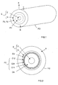
- the invention provides a method dedicated to the production of fibered elements (herein, optical fibers), for example of the type illustrated in Figure 1 .
- the method consists firstly, starting from a first part C, here constituting a fiber core (or primary preform), in surrounding this core C with a second part, here constituting an optical cladding G, and having the first optical properties, so as to constitute an assembly E.
- the first optical properties are here defined by at least one optical fiber precursor designed to constitute at least one optical filter FE, once the optical fiber F0 has been produced.
- the core C is for example realised by several layers of silica of different refractive indices, so as to exhibit a selected refractive index profile.
- the assembly E is drawn in a longitudinal direction Y in order to increase its longitudinal dimension and reduce its transversal dimension (here its diameter on the X-axis).
- Increasing the longitudinal dimension and reducing its diameter are chosen so as to ensure transformation of at least certain of the first optical properties of optical cladding G and, consequently, of optical filter FE precursor, and of the second optical properties allowing it to selectively filter, in a direction substantially perpendicular to the fiber axis (Y), photons of which the wavelengths fall within at least one selected spectral band.
- the optical filter FE resulting from drawing the optical filter precursor has optical properties allowing it to selectively filter certain photons.
- the assembly E can then be surrounded with a substantially transparent cladding R, in order to constitute an optical fiber F0.
- the optical filter FE and more precisely its precursor, can be made in different ways.
- a first manner is diagrammatically illustrated in Figure 1 . More precisely, in this example, the optical cladding G is preferably made of two parts P1 and P2.
- the inner part P1 is formed around core C, for example by injecting grains of pure silica (of refractive index of around 1.456) heated to a very high temperature by a plasma torch TP (see Figure 6A ).
- the outer part P2 is formed around inner part P1, for example by injecting grains of colored silica also heated to very high temperature by means of the plasma torch TP.
- the pigment employed for coloring the silica designed to constitute the outer part P2, and consequently the future optical filter FE, is chosen so as not to diffuse towards the core C, via the inner part P1 of the optical cladding G. Further, the thickness of the colored silica layer constituting the outer part P2 is chosen sufficiently small so as not to affect the mechanical properties of the final optical fiber F0.
- the outer part P2 of the optical cladding G constitutes, once the assembly E has been drawn, an optical filter FE responsible for reflecting (or emitting), in a direction substantially perpendicular to the fiber axis, the photons of which the wavelengths fall at least in the selected spectral band and/or responsible for absorbing at least partially, photons of which the wavelengths do not fall in the selected spectral band.
- the modification of optical properties during the drawing stage will be reflected by a variation (reduction) in perceived coloration intensity, brought about by the pigment being distributed over a significant length of fiber.
- the optical fiber F0 should be able to be located (or detected) by an optical sensing instrument not necessarily operating in the visible spectrum, but for example in the ultraviolet or infrared spectrum.
- the optical coding of the optical fiber F0 consists in making its optical cladding G reflecting for photons of which the wavelengths fall in a spectral band comprised in the ultraviolet or infrared.
- the optical cladding G ensures several filtering operations in several different spectral bands, for example for rendering the optical fiber F0 able to be located both by the eye and by an optical sensing instrument operating in the ultraviolet or infrared.
- the precursor of the future optical filter FE is constituted within the optical cladding G by means of at least one layer C1i of the first material, having a first selected refractive index n1, and a layer C2i of a second material, having a second selected refractive index n2, different from the first one n1, and surrounding layer C1i.
- the filter FE includes two layers C11 and C12 of the first material, separated by a layer C21 of the second material.
- Figure 3 illustrates diagrammatically the refractive index profile of the core C and the optical cladding G of the optical fiber F0 of Figure 2 .
- the core C has a particular refractive index profile, but this is not obligatory.
- the final thicknesses d1 and d2 (once the assembly E has been drawn) and the refractive indices n1 and n2 of the layers C1i and C2i of the first and second materials are chosen as a function of the spectral band in which optical filter FE should be reflecting.
- the values d1' and d2' which should present the layers of first and second material prior to the drawing stage can be determined. These values d1' and d2' depend in effect on the drawing factor of the core-cladding assembly E.
- the reduction factor of thicknesses d1' and d2' brought about by the drawing stage is in effect substantially equal to the drawing factor (by 1:1 symmetry).
- n1/n2 comprised between about 1.02 and about 1.5 and more preferably between 1.05 and 1.3.
- filter FE it is preferable for filter FE to be placed in an intermediate part of the optical cladding G.
- optical cladding G In order to further enhance the wavelength filtering mechanism provided by the optical cladding G, one can, as illustrated in Figure 5 , provide in said optical cladding G, before it is not drawn and to supplement optical filter FE, a precursor having an absorbent structure SA.
- the optical filter FE Like in the case of the optical filter FE, once the assembly E has been drawn, at least certain of the optical properties of the second precursor become transformed so as to allow absorption of photons of which the wavelengths fall in at least one selected spectral band, different from the filtering spectral band, and preferably complementary thereto. Thus, by absorbing photons which are not reflected by the optical filter FE (and of which the wavelengths do not fall in the filtering spectral band), the coloring effect of the optical fiber F0 is enhanced.
- the absorbing structure SA is preferably interposed between the core CE and the optical filter FE during the optical cladding G formation stage. It can, for example, be constituted of one or several layers of silica including an organic, inorganic or mineral pigment. This absorbing structure SA can be made in the same way as the other layers (C1i, C2i, CV and CA) of the optical cladding G, in other words by high-temperature heating using a plasma torch TP.
- optical fibers F0 of the type discussed above with reference to figures 2-5 .
- a first example is designed to provide an optical fiber of 125 ⁇ m diameter (excluding protective coating R), of blue color, in other words reflecting photons having wavelengths comprised between about 450 nm and 500 nm.
- the assembly E is drawn so that it has, once drawn, a diameter of 125 ⁇ m, corresponding to a drawing factor of 1000.
- the drawn assembly E' is covered by a transparent protective covering R so as to complete the manufacture of optical fiber F0.
- This arrangement makes it possible to obtain a reflection coefficient of the order of 85% for photons of which the wavelengths fall in the spectral band comprised between 450 nm and 500 nm. Consequently, the optical fiber F0 appears blue in color.
- a second example is designed to provide an optical fiber of 125 ⁇ m diameter (excluding protective covering R), of red color, in other words reflecting photons of wavelengths comprised between about 620 nm and 700 nm.
- the assembly E is drawn so as to have, once drawn, a diameter of 125 ⁇ m, corresponding to a drawing factor of 1000.
- the drawn assembly E' is covered with a transparent protective covering R so as to complete the manufacture of the optical fiber F0.
- This arrangement makes it possible to obtain a reflection coefficient of the order of 80% for photons of which the wavelengths fall in the spectral band comprised between 650 nm and 700 nm. Consequently, the optical fiber F0 appears red in colour.
- a third example is designed to provide an optical fiber of 125 ⁇ m diameter (excluding protective covering R), of intense red color, in other words reflecting photons of wavelengths comprised between about 620 nm and 700 nm.
- a precursor of an absorption structure SA constituted by one or several layers of an organic, inorganic or mineral chromatic material designed to absorb all photons of wavelength less than 600 nm and to reflect all photons of wavelengths greater than 600 nm is associated with the optical cladding G of the second example, preferably between the core C and the optical filter FE precursor.
- pigments the proparts of which are comprised between about 0.01% by weight and 3% by weight.
- inorganic pigments such as oxides (in particular red iron oxide Fe 2 O 3 ) can be used, or sulfides (in particular of cadmium red CdS or CdSe).
- organic pigments such as Styryl 17 or DOTC lodite.
- a fourth example is designed, like the third example, to provide an optical fiber of 125 ⁇ m diameter (excluding protective covering R) of intense red color.
- an absorption structure SA precursor is used having one or several layers of an achromatic material having substantially uniform absorption in the visible spectrum.
- This chromatic material can for example be carbon black (C), or black iron oxide (Fe 3 O 4 ), or white zinc (ZnO), or, again, an inorganic material such as a pigment or anneline black, or yet again, an organic material.
- This installation resembles those used industrially for building up thickness primary preforms for optical fibers with silica by an external plasma deposition method.
- grains of silica are injected into a plasma torch, they melt and are projected onto the primary preform for building up thickness.
- the installation according to the invention actually distinguishes itself from known installations for building up thickness by the fact that it has two different grain feed devices instead of one single one, so as to allow building-up of the optical fiber precursor FE and, optionally, of the absorbing structure SA precursor.
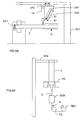
- the installation according to the invention comprises firstly a first drive device DE1 responsible for rotating the core C of a fibered element, and first and second feed devices DA1 and DA2 responsible for selectively supplying at a first and second outlet S1 and S2, respectively, in alternating fashion, first and second materials designed to constitute at least the optical cladding G and its optical filter FE precursor.
- first and second materials are respectively doped silica (or colored silica) and substantially pure silica, in grain form.
- the installation further comprises a first heating device TP, such as for example a plasma torch responsible for providing a high temperature flame in a region located in the neighborhood of first and second outlets S1 and S2, and a second drive device DE2, mounted on a carrier SU1 and responsible for driving the first and second feed devices DA1 and DA2 in linear motion along with heating device TP, in the neighborhood of the core C, in order to provide for the core-cladding assembly E to be built up.
- a first heating device TP such as for example a plasma torch responsible for providing a high temperature flame in a region located in the neighborhood of first and second outlets S1 and S2, and a second drive device DE2, mounted on a carrier SU1 and responsible for driving the first and second feed devices DA1 and DA2 in linear motion along with heating device TP, in the neighborhood of the core C, in order to provide for the core-cladding assembly E to be built up.
- the latter is operated so as to rotate the core C.
- the second feed device DA2 is controlled so as to supply at the second outlet S2, a jet of pure silica in grains so as to pass through the flame of plasma torch TP.
- first feed device DA1 is not operating.
- the first drive device DE1 moves in linear motion so that an "upstream" layer CA having a refractive index n2 and a chosen thickness, is uniformly deposited over the whole useful length of the core C.
- optical filter FE precursor build-up phase now starts.
- a first feed device DA1 is set to deliver at the first outlet S1 a jet of (for example) doped silica grains so that they pass through the flame of plasma torch TP.
- the second feed device DA2 is not operating.
- the first drive device DE1 drives it in linear motion so that a first layer C11 having a refractive index n1 and a chosen thickness, is uniformly deposited over the whole useful length of the core C.
- the installation can comprise a carrier SU2 responsible for holding the core-cladding assembly E, a second heating device DC responsible for heating the end of the core-cladding assembly E, not yet drawn, and a third drive device D3 responsible for drawing, in a controlled fashion, the heated end of the assembly E, and winding the drawn element E'.
- a carrier SU2 responsible for holding the core-cladding assembly E
- a second heating device DC responsible for heating the end of the core-cladding assembly E, not yet drawn
- a third drive device D3 responsible for drawing, in a controlled fashion, the heated end of the assembly E, and winding the drawn element E'.
- the installation can comprise an enveloping device DER, preferably in-line (for example located just ahead of winding device D-3).
- the covering R that is deposited is for example a substantially transparent resin.
- a permanent coloring and/or optical coding is obtained by providing a chromatic filter, by adding a coloring, e.g. in the form of a pigment, or by both providing a chromatic filter and adding a coloring. Further, it is no longer necessary to provide a multitude of colored resins, which is expensive in terms of production and storage cost, and one is no longer limited to a few colors imposed by said colored resins, since one can from now on filter practically any wavelength whatsoever.
- the invention is not limited to the embodiments of an installation for producing a fibered element and the fibered element production method discussed above, just by way of example, also covers all variations thereof that the skilled person might envisage within the scope of the following claims.
- the production of a circular cross-section optical fiber is not limited either to this type of cross-section, nor to this type of fibered element. It indeed concerns all fibered elements regardless of the shape of their cross-section, whenever they include a first part of vitreous material surrounded by a second part having a selective optical filtering function once drawing is terminated.
- the production of a fibered element in silica is not limited to this type of vitreous material. It indeed covers (in particular) all types of glass provided these can be subject to softening and one can modify their refractive index by suitable means. Consequently, the heating device designed to form the optical cladding prior to drawing can be different from a plasma torch. Obviously, the various materials used should be compatible between themselves and should be able to be drawn with important drawing factors without any danger of breaking.
- the production of a fibered element adapted to the optical communications field is not limited to this field of application. It concerns indeed other fields of application such as for example the textile field and more particularly weaving (the production of woven fiber structures either just using the fibered elements of the invention or these along with other types of filaments or fibers), or decoration, and in particular the production of matrices in which the fibered elements of the invention can be embedded, optionally after having been cut into small pieces.
- the selective optical filter can also constitute the second part, in particular in the case of a glass fiber.
- the first part of vitreous material is surrounded by the selective optical filter and optionally by an additional transparent covering.
Landscapes
- Physics & Mathematics (AREA)
- Chemical & Material Sciences (AREA)
- Engineering & Computer Science (AREA)
- Life Sciences & Earth Sciences (AREA)
- Materials Engineering (AREA)
- Optics & Photonics (AREA)
- Organic Chemistry (AREA)
- Geochemistry & Mineralogy (AREA)
- General Physics & Mathematics (AREA)
- General Life Sciences & Earth Sciences (AREA)
- Chemical Kinetics & Catalysis (AREA)
- General Chemical & Material Sciences (AREA)
- Manufacturing & Machinery (AREA)
- Composite Materials (AREA)
- Optical Filters (AREA)
- Light Guides In General And Applications Therefor (AREA)
- Inorganic Fibers (AREA)
- Spinning Methods And Devices For Manufacturing Artificial Fibers (AREA)
- Glass Compositions (AREA)
Claims (21)
- Verfahren zur Herstellung eines gefaserten Elements (F0), dadurch gekennzeichnet, dass es ausi) einem Ausbilden einer Anordnung (E) durch Umgeben eines ersten Teils (C) eines glasartigen Materials mit einem zweiten Teil (G) mit ersten optischen Eigenschaften undii) dann einem Ziehen der Anordnung (E) in einer Längsrichtung, um ihre Längsabmessung zu erhöhen während mindestens eine ihrer Querabmessungen verringert wird,besteht, wobei das Erhöhen und Verringern derart gewählt wird, um zumindest bestimmte der ersten optischen Eigenschaften des zweiten Teils (G) in zweite optische Eigenschaften umzuwandeln, welche es ermöglichen, Photonen, deren Wellenlänge in zumindest ein ausgewähltes Spektralband fällt, in einer Richtung im Wesentlichen senkrecht zu der Längsrichtung der gezogenen Anordnung selektiv zu filtern.
- Verfahren nach Anspruch 1, dadurch gekennzeichnet, dass das Ausbilden der Anordnung (E) aus einem Umgeben des ersten Teils (C) mit einem zweiten Teil (G) besteht, welches ein Innenteil (P1) aufweist, welches durch ein Außenteil (P2) verlängert ist, welches ausgestaltet ist, sobald es gezogen ist, die Photonen, deren Wellenlängen in zumindest das ausgewählte Spektralband fallen, zu filtern.
- Verfahren nach Anspruch 2, dadurch gekennzeichnet, dass das Außenteil (P2) aus einem gefärbten Material gefertigt ist, wobei das Filtern aus einem Reflektieren oder Aussenden der Photonen, deren Wellenlängen in das ausgewählte Spektralband fallen, und/oder aus einem Absorbieren von Photonen, deren Wellenlängen in das ausgewählte Spektralband fallen, besteht.
- Verfahren nach einem der Ansprüche 2 und 3, dadurch gekennzeichnet, dass das erste Teil (C) aus Siliziumdioxid gefertigt ist und das gefärbte Material, welches das Außenteil (P2) bildet, gefärbtes Siliziumdioxid ist.
- Verfahren nach einem der Ansprüche 1-4, dadurch gekennzeichnet, dass das Ausbilden der Anordnung (E) aus einem Umgeben des ersten Teils (C) mit einem zweiten Teil (G), welches eine optische Filtervorstufe (FE) umfasst, welche ausgestaltet ist, sobald die Anordnung (E) gezogen wurde, ein optisches Filter zu definieren, welches für ein Reflektieren der Photonen, deren Wellenlängen in das gewählte Spektralband fallen, zuständig ist, besteht.
- Verfahren nach Anspruch 5, dadurch gekennzeichnet, dass die optische Filtervorstufe (FE) aus mindestens einer Schicht (C1i) eines ersten Materials mit einem ersten ausgewählten Brechungsindex (n1) gebildet ist, welche von einer Schicht (C2i) eines zweiten Materials mit einem zweiten ausgewählten Brechungsindex (n2), welcher unterschiedlich zu dem ersten Brechungsindex (n1) ist, umgeben ist.
- Verfahren nach Anspruch 6, dadurch gekennzeichnet, dass die Schichten (C1i, C2i) aus erstem und zweitem Material, sobald sie gezogen sind, jeweilige Dicken (d1, d2) aufweisen, welche zueinander, zu dem ersten (n1) und zweiten (n2) Brechungsindex und zu der Mittenwellenlänge λ des gewählten Spektralbandes über die Beziehung λ=2(n1·d1+n2·d2) in Beziehung stehen.
- Verfahren nach einem der Ansprüche 6 und 7, dadurch gekennzeichnet, dass das Verhältnis zwischen dem ersten (n1) und zweiten (n2) Brechungsindex zwischen 1,02 und 1,5 liegt.
- Verfahren nach einem der Ansprüche 6-8, dadurch gekennzeichnet, dass die optische Filtervorstufe (FE) durch eine ausgewählte Anzahl von Wechseln von Schichten (C1i) aus dem ersten Material und Schichten (C2i) aus dem zweiten Material gebildet wird.
- Verfahren nach Anspruch 9, dadurch gekennzeichnet, dass die Anzahl mindestens gleich 1 und höchstens gleich 40 ist.
- Verfahren nach einem der Ansprüche 6-10, dadurch gekennzeichnet, dass zwischen dem ersten Teil (C) und der optischen Filtervorstufe (FE) eine dicke Schicht (CA) aus einem Material mit einem Brechungsindex, welcher zwischen dem ersten (n1) und zweiten (n2) Brechungsindex liegt, angeordnet ist, und dass eine dicke Schicht (CV) aus einem Material mit einem Brechungsindex, welcher zwischen dem ersten (n1) und zweiten (n2) Brechungsindex liegt, nach der optischen Filtervorstufe (FE) hinzugefügt wird.
- Verfahren nach einem der Ansprüche 6-11, dadurch gekennzeichnet, dass innerhalb des zweiten Teils (G) vor dem Ziehen eine absorbierende Struktur (SA) ausgebildet wird, welche ausgestaltet ist, nach einem Ziehen, Photonen, deren Wellenlängen in mindestens einem weiteren ausgewählten Spektralband enthalten sind, zu absorbieren.
- Verfahren nach Anspruch 12, dadurch gekennzeichnet, dass die absorbierende Struktur (SA) zwischen dem ersten Teil (C) und der optischen Filtervorstufe (FE) angeordnet ist und mindestens eine Schicht eines Materials aus Siliziumdioxid, welches ein Pigment umfasst, welches aus der Gruppe ausgewählt ist, die organische, anorganische oder mineralische Pigmente umfasst, bildet.
- Verfahren nach einem der Ansprüche 6-13, dadurch gekennzeichnet, dass das erste Teil (C) aus einem Siliziumdioxid basierten Material gefertigt ist, welches ein ausgewähltes Brechungsindexprofil aufweist, wobei das erste Material aus im Wesentlichen reinem oder dotiertem Siliziumdioxid besteht, welches einen größeren Brechungsindex als der Brechungsindex von Siliziumdioxid aufweist, und wobei das zweite Material dotiertes Siliziumdioxid oder im Wesentlichen reines Siliziumdioxid ist, welches einen Brechungsindex unterhalb des Brechungsindex von Siliziumdioxid aufweist.
- Verfahren nach einem der Ansprüche 1-14, dadurch gekennzeichnet, dass die gezogene Anordnung (E') nach dem Ziehen mit einer im Wesentlichen transparenten Abdeckung (R) umgeben wird.
- Optische Faser (F0), dadurch gekennzeichnet, dass sie aus einem gefaserten Element gebildet ist, welches durch das Verfahren nach einem der vorhergehenden Ansprüche hergestellt wurde.
- Gefaserte Struktur, dadurch gekennzeichnet, dass sie aus einer Vielzahl von gefaserten Elementen (F0) gebildet ist, welche mittels des Verfahrens nach einem der Ansprüche 1-15 hergestellt wurden und in eine Polymermatrix eingebettet sind.
- Gefaserte Struktur, dadurch gekennzeichnet, dass sie aus einer Vielzahl von gefaserten Elementen (F0) gebildet ist, welche mittels des Verfahrens nach einem der Ansprüche 1-15 hergestellt wurden und gewebt sind.
- Anlage zur Herstellung gefaserter Elemente, dadurch gekennzeichnet, dass sie umfasst:ein erstes Antriebsmittel (DE1), welches geeignet ist, ein erstes Teil einer optischen Faser (F0), das aus einem gläsernen Material gefertigt ist, zu drehen,ein erstes (DA1) und ein zweites (DA2) Zuführungsmittel, welche geeignet sind, an einem ersten (S1) und einem zweiten (S2) Auslass jeweils selektiv und in einer abwechselnden Art und Weise ein erstes und ein zweites Material bereitzustellen, welche ausgestaltet sind, um das erste Teil (C) mindestens ein zweites Teil (G) und seine optische Filtervorstufe (FE) zu bilden,ein erstes Heizmittel (TP), welches geeignet ist, einen Bereich, welcher in der Umgebung des ersten (S1) und zweiten (S2) Auslasses angeordnet ist, auf eine ausgewählte Temperatur zu bringen, undein zweites Antriebsmittel (DE2), welches geeignet ist, das erste (DA1) und zweite (DA2) Zuführungsmittel und das erste Heizmittel (TP) in einer linearen Bewegung in die Umgebung des Kerns (C) zu führen, um eine Anordnung (E), welche das erste Teil (C) umgeben von dem zweiten Teil (G) umfasst, in Übereinstimmung mit dem Verfahren nach einem der Ansprüche 1-15 zu erzeugen.
- Anlage nach Anspruch 19, dadurch gekennzeichnet, dass sie ein zweites Heizmittel (DC), welches geeignet ist, einen Teil der Anordnung (E) zu heizen, und ein drittes Antriebsmittel (DE3), welches geeignet ist, ein erwärmtes Endteil der ist, einen Teil der Anordnung (E) zu heizen, und ein drittes Antriebsmittel (DE3), welches geeignet ist, ein erwärmtes Endteil der Anordnung (E) zu ziehen, um die Längsabmessung davon zu erhöhen, während gleichzeitig ihre Querabmessungen verringert werden, und die gezogene Anordnung (E') aufzuwickeln, umfasst.
- Anlage nach einem der Ansprüche 19 und 20, dadurch gekennzeichnet, dass sie ein abdeckendes Mittel (DER) umfasst, welches geeignet ist, die gezogene Anordnung (E') mit einer im Wesentlichen transparenten Abdeckung (R) zu umgeben.
Applications Claiming Priority (2)
| Application Number | Priority Date | Filing Date | Title |
|---|---|---|---|
| FR0451301A FR2871796B1 (fr) | 2004-06-21 | 2004-06-21 | Procede et installation de fabrication d'un element fibre a filtre de lumiere selectif |
| PCT/NL2005/000442 WO2005124417A1 (en) | 2004-06-21 | 2005-06-17 | Method and installation for producing a fibered element with a light-selective filter |
Publications (2)
| Publication Number | Publication Date |
|---|---|
| EP1759232A1 EP1759232A1 (de) | 2007-03-07 |
| EP1759232B1 true EP1759232B1 (de) | 2008-02-27 |
Family
ID=34946030
Family Applications (1)
| Application Number | Title | Priority Date | Filing Date |
|---|---|---|---|
| EP05752873A Expired - Lifetime EP1759232B1 (de) | 2004-06-21 | 2005-06-17 | Verfahren und installation zur herstellung eines gefaserten elements mit einem lichtselektiven filter |
Country Status (7)
| Country | Link |
|---|---|
| US (1) | US20080000269A1 (de) |
| EP (1) | EP1759232B1 (de) |
| CN (1) | CN1938625B (de) |
| AT (1) | ATE387641T1 (de) |
| DE (1) | DE602005005051T2 (de) |
| FR (1) | FR2871796B1 (de) |
| WO (1) | WO2005124417A1 (de) |
Families Citing this family (2)
| Publication number | Priority date | Publication date | Assignee | Title |
|---|---|---|---|---|
| CA3030851A1 (en) * | 2016-07-15 | 2018-01-18 | Light Field Lab, Inc. | Selective propagation of energy in light field and holographic waveguide arrays |
| JP7793526B2 (ja) * | 2020-02-25 | 2026-01-05 | バイオリテック ウンテルネーメンスベタイリグングス ドライ アーゲー | プリフォーム、そのプリフォームの製造方法、及び光ファイバの製造方法 |
Family Cites Families (13)
| Publication number | Priority date | Publication date | Assignee | Title |
|---|---|---|---|---|
| US4243398A (en) * | 1978-02-09 | 1981-01-06 | Nippon Electric Co., Ltd. | Method of producing dielectric diffraction gratings or dielectric multilayer interference filters |
| FR2656734B1 (fr) * | 1990-01-03 | 1992-03-20 | Filotex Sa | Cable electrique ou a fibres optiques marquable par plusieurs types de lasers. |
| FR2708754B1 (fr) * | 1993-08-04 | 1995-09-08 | Alcatel Cable | Câble à fibres optiques et procédé de réalisation associé. |
| FR2713621B1 (fr) * | 1993-12-14 | 1996-01-05 | Alcatel Fibres Optiques | Procédé de recharge par plasma d'une préforme pour fibre optique et fibre optique issue de la préforme rechargée selon ce procédé. |
| US5881196A (en) * | 1996-10-24 | 1999-03-09 | Phillips; Stephen | Waveguide security device |
| EP1018657A4 (de) * | 1998-07-16 | 2007-06-27 | Nippon Sheet Glass Co Ltd | Optisches element mit brechungsindexverteilung stablinsenmatrix mit brechungsindexverteilung |
| US6215092B1 (en) * | 1999-06-08 | 2001-04-10 | Alcatel | Plasma overcladding process and apparatus having multiple plasma torches |
| US6504982B1 (en) * | 1999-06-30 | 2003-01-07 | Alcatel | Incorporation of UV transparent perlescent pigments to UV curable optical fiber materials |
| US6321014B1 (en) * | 1999-11-01 | 2001-11-20 | Alcatel | Method for manufacturing optical fiber ribbon |
| AU2002223515A1 (en) * | 2000-11-20 | 2002-05-27 | Crystal Fibre A/S | A micro-structured optical fibre |
| US6801698B2 (en) * | 2001-04-12 | 2004-10-05 | Omniguide Communications | High index-contrast fiber waveguides and applications |
| US6988380B2 (en) * | 2002-08-15 | 2006-01-24 | Ceramoptec Industries, Inc. | Method of silica optical fiber preform production |
| US20040107735A1 (en) * | 2002-12-04 | 2004-06-10 | Fitel Usa Corp. | Rod-in-tube optical fiber preform and method |
-
2004
- 2004-06-21 FR FR0451301A patent/FR2871796B1/fr not_active Expired - Fee Related
-
2005
- 2005-06-17 WO PCT/NL2005/000442 patent/WO2005124417A1/en not_active Ceased
- 2005-06-17 EP EP05752873A patent/EP1759232B1/de not_active Expired - Lifetime
- 2005-06-17 DE DE602005005051T patent/DE602005005051T2/de not_active Expired - Lifetime
- 2005-06-17 CN CN2005800097631A patent/CN1938625B/zh not_active Expired - Fee Related
- 2005-06-17 AT AT05752873T patent/ATE387641T1/de not_active IP Right Cessation
- 2005-06-17 US US11/568,461 patent/US20080000269A1/en not_active Abandoned
Also Published As
| Publication number | Publication date |
|---|---|
| WO2005124417A1 (en) | 2005-12-29 |
| FR2871796B1 (fr) | 2006-09-15 |
| DE602005005051D1 (de) | 2008-04-10 |
| ATE387641T1 (de) | 2008-03-15 |
| CN1938625B (zh) | 2010-05-12 |
| EP1759232A1 (de) | 2007-03-07 |
| US20080000269A1 (en) | 2008-01-03 |
| CN1938625A (zh) | 2007-03-28 |
| DE602005005051T2 (de) | 2009-03-19 |
| FR2871796A1 (fr) | 2005-12-23 |
Similar Documents
| Publication | Publication Date | Title |
|---|---|---|
| KR102032533B1 (ko) | 광 섬유 조명 시스템 및 방법 | |
| JP6782322B2 (ja) | 光拡散光ファイバー、ファイバーバンドル及び照明システム | |
| US9093003B2 (en) | Manipulation of color illumination using light diffusing fiber | |
| US9217826B2 (en) | Multi-wavelength light source using light diffusing fibers | |
| KR101423203B1 (ko) | 광 섬유 제조 방법 및 이에 의해 획득한 광 섬유 | |
| US20150062954A1 (en) | Phosphor printing on light diffusing fiber based textile | |
| US6160938A (en) | Concentric lay stranding for optical fiber cable | |
| JP2000351654A (ja) | 一又は二以上の不均質領域を有する被覆ファイバ線およびその同一物品を作製する方法 | |
| US20160103261A1 (en) | Optical fiber illumination systems producing color movement | |
| WO2013066668A1 (en) | Light diffusing optical fiber with uv protection layer | |
| DE102008009138A1 (de) | Seitenemittierende brechwertangepasste Faser | |
| US5016973A (en) | Cable reinforcement for an optical fiber cable | |
| EP1065546B1 (de) | Einlagerung von UV transparenten irisierenden Pigmenten in UV härtbare faseroptische Materialien | |
| DE102008009139B4 (de) | Seitenemittierende Stufenindexfaser, Faserbündel und Flächengebilde und deren Verwendungen sowie Preformen und Verfahren zu deren Herstellung | |
| EP0391742A3 (de) | Bildfaser, Bildfaservorform und Herstellungsverfahren | |
| US20080000269A1 (en) | Method and Installation for Producing a Fibered Element With a Light-Selective Filter | |
| AU615333B2 (en) | Light energy transmitting optical fiber cable | |
| US20130188915A1 (en) | Plastic optical fiber unit and plastic optical fiber cable using same | |
| EP2766754A1 (de) | Farbenbeleuchtungsanzeigetafel mit lichtstreuender faser | |
| CA2119826A1 (en) | Partially detached core optical waveguide | |
| CA1087889A (en) | Optical fiber waveguide with effective refractive index profile | |
| CA2509263A1 (en) | Optical fibre having low splice loss and method for making it | |
| Jung et al. | Tunable bandpass filter by concatenated microstructured fiber-hollow optical fiber based on bend-loss edge shift | |
| KR20000056361A (ko) | 광섬유망을 이용한 보안시스템용 광섬유 |
Legal Events
| Date | Code | Title | Description |
|---|---|---|---|
| PUAI | Public reference made under article 153(3) epc to a published international application that has entered the european phase |
Free format text: ORIGINAL CODE: 0009012 |
|
| 17P | Request for examination filed |
Effective date: 20060804 |
|
| AK | Designated contracting states |
Kind code of ref document: A1 Designated state(s): AT BE BG CH CY CZ DE DK EE ES FI FR GB GR HU IE IS IT LI LT LU MC NL PL PT RO SE SI SK TR |
|
| RAP1 | Party data changed (applicant data changed or rights of an application transferred) |
Owner name: DRAKA COMTEQ B.V. |
|
| RAP1 | Party data changed (applicant data changed or rights of an application transferred) |
Owner name: DRAKA COMTEQ B.V. |
|
| GRAP | Despatch of communication of intention to grant a patent |
Free format text: ORIGINAL CODE: EPIDOSNIGR1 |
|
| DAX | Request for extension of the european patent (deleted) | ||
| GRAS | Grant fee paid |
Free format text: ORIGINAL CODE: EPIDOSNIGR3 |
|
| GRAA | (expected) grant |
Free format text: ORIGINAL CODE: 0009210 |
|
| AK | Designated contracting states |
Kind code of ref document: B1 Designated state(s): AT BE BG CH CY CZ DE DK EE ES FI FR GB GR HU IE IS IT LI LT LU MC NL PL PT RO SE SI SK TR |
|
| REG | Reference to a national code |
Ref country code: GB Ref legal event code: FG4D |
|
| REG | Reference to a national code |
Ref country code: CH Ref legal event code: EP |
|
| REG | Reference to a national code |
Ref country code: IE Ref legal event code: FG4D |
|
| REF | Corresponds to: |
Ref document number: 602005005051 Country of ref document: DE Date of ref document: 20080410 Kind code of ref document: P |
|
| PG25 | Lapsed in a contracting state [announced via postgrant information from national office to epo] |
Ref country code: IS Free format text: LAPSE BECAUSE OF FAILURE TO SUBMIT A TRANSLATION OF THE DESCRIPTION OR TO PAY THE FEE WITHIN THE PRESCRIBED TIME-LIMIT Effective date: 20080627 Ref country code: ES Free format text: LAPSE BECAUSE OF FAILURE TO SUBMIT A TRANSLATION OF THE DESCRIPTION OR TO PAY THE FEE WITHIN THE PRESCRIBED TIME-LIMIT Effective date: 20080607 Ref country code: FI Free format text: LAPSE BECAUSE OF FAILURE TO SUBMIT A TRANSLATION OF THE DESCRIPTION OR TO PAY THE FEE WITHIN THE PRESCRIBED TIME-LIMIT Effective date: 20080227 |
|
| NLV1 | Nl: lapsed or annulled due to failure to fulfill the requirements of art. 29p and 29m of the patents act | ||
| PG25 | Lapsed in a contracting state [announced via postgrant information from national office to epo] |
Ref country code: AT Free format text: LAPSE BECAUSE OF FAILURE TO SUBMIT A TRANSLATION OF THE DESCRIPTION OR TO PAY THE FEE WITHIN THE PRESCRIBED TIME-LIMIT Effective date: 20080227 |
|
| PG25 | Lapsed in a contracting state [announced via postgrant information from national office to epo] |
Ref country code: BE Free format text: LAPSE BECAUSE OF FAILURE TO SUBMIT A TRANSLATION OF THE DESCRIPTION OR TO PAY THE FEE WITHIN THE PRESCRIBED TIME-LIMIT Effective date: 20080227 Ref country code: PL Free format text: LAPSE BECAUSE OF FAILURE TO SUBMIT A TRANSLATION OF THE DESCRIPTION OR TO PAY THE FEE WITHIN THE PRESCRIBED TIME-LIMIT Effective date: 20080227 Ref country code: SI Free format text: LAPSE BECAUSE OF FAILURE TO SUBMIT A TRANSLATION OF THE DESCRIPTION OR TO PAY THE FEE WITHIN THE PRESCRIBED TIME-LIMIT Effective date: 20080227 |
|
| PG25 | Lapsed in a contracting state [announced via postgrant information from national office to epo] |
Ref country code: CZ Free format text: LAPSE BECAUSE OF FAILURE TO SUBMIT A TRANSLATION OF THE DESCRIPTION OR TO PAY THE FEE WITHIN THE PRESCRIBED TIME-LIMIT Effective date: 20080227 Ref country code: SK Free format text: LAPSE BECAUSE OF FAILURE TO SUBMIT A TRANSLATION OF THE DESCRIPTION OR TO PAY THE FEE WITHIN THE PRESCRIBED TIME-LIMIT Effective date: 20080227 Ref country code: PT Free format text: LAPSE BECAUSE OF FAILURE TO SUBMIT A TRANSLATION OF THE DESCRIPTION OR TO PAY THE FEE WITHIN THE PRESCRIBED TIME-LIMIT Effective date: 20080721 Ref country code: SE Free format text: LAPSE BECAUSE OF FAILURE TO SUBMIT A TRANSLATION OF THE DESCRIPTION OR TO PAY THE FEE WITHIN THE PRESCRIBED TIME-LIMIT Effective date: 20080527 Ref country code: DK Free format text: LAPSE BECAUSE OF FAILURE TO SUBMIT A TRANSLATION OF THE DESCRIPTION OR TO PAY THE FEE WITHIN THE PRESCRIBED TIME-LIMIT Effective date: 20080227 Ref country code: NL Free format text: LAPSE BECAUSE OF FAILURE TO SUBMIT A TRANSLATION OF THE DESCRIPTION OR TO PAY THE FEE WITHIN THE PRESCRIBED TIME-LIMIT Effective date: 20080227 |
|
| PG25 | Lapsed in a contracting state [announced via postgrant information from national office to epo] |
Ref country code: RO Free format text: LAPSE BECAUSE OF FAILURE TO SUBMIT A TRANSLATION OF THE DESCRIPTION OR TO PAY THE FEE WITHIN THE PRESCRIBED TIME-LIMIT Effective date: 20080227 |
|
| ET | Fr: translation filed | ||
| PLBE | No opposition filed within time limit |
Free format text: ORIGINAL CODE: 0009261 |
|
| STAA | Information on the status of an ep patent application or granted ep patent |
Free format text: STATUS: NO OPPOSITION FILED WITHIN TIME LIMIT |
|
| PG25 | Lapsed in a contracting state [announced via postgrant information from national office to epo] |
Ref country code: MC Free format text: LAPSE BECAUSE OF NON-PAYMENT OF DUE FEES Effective date: 20080630 Ref country code: LT Free format text: LAPSE BECAUSE OF FAILURE TO SUBMIT A TRANSLATION OF THE DESCRIPTION OR TO PAY THE FEE WITHIN THE PRESCRIBED TIME-LIMIT Effective date: 20080227 |
|
| 26N | No opposition filed |
Effective date: 20081128 |
|
| PG25 | Lapsed in a contracting state [announced via postgrant information from national office to epo] |
Ref country code: IE Free format text: LAPSE BECAUSE OF NON-PAYMENT OF DUE FEES Effective date: 20080617 Ref country code: BG Free format text: LAPSE BECAUSE OF FAILURE TO SUBMIT A TRANSLATION OF THE DESCRIPTION OR TO PAY THE FEE WITHIN THE PRESCRIBED TIME-LIMIT Effective date: 20080527 Ref country code: EE Free format text: LAPSE BECAUSE OF FAILURE TO SUBMIT A TRANSLATION OF THE DESCRIPTION OR TO PAY THE FEE WITHIN THE PRESCRIBED TIME-LIMIT Effective date: 20080227 |
|
| PG25 | Lapsed in a contracting state [announced via postgrant information from national office to epo] |
Ref country code: CY Free format text: LAPSE BECAUSE OF FAILURE TO SUBMIT A TRANSLATION OF THE DESCRIPTION OR TO PAY THE FEE WITHIN THE PRESCRIBED TIME-LIMIT Effective date: 20080227 |
|
| PG25 | Lapsed in a contracting state [announced via postgrant information from national office to epo] |
Ref country code: IT Free format text: LAPSE BECAUSE OF FAILURE TO SUBMIT A TRANSLATION OF THE DESCRIPTION OR TO PAY THE FEE WITHIN THE PRESCRIBED TIME-LIMIT Effective date: 20080227 |
|
| REG | Reference to a national code |
Ref country code: CH Ref legal event code: PL |
|
| PG25 | Lapsed in a contracting state [announced via postgrant information from national office to epo] |
Ref country code: LI Free format text: LAPSE BECAUSE OF NON-PAYMENT OF DUE FEES Effective date: 20090630 Ref country code: CH Free format text: LAPSE BECAUSE OF NON-PAYMENT OF DUE FEES Effective date: 20090630 |
|
| PG25 | Lapsed in a contracting state [announced via postgrant information from national office to epo] |
Ref country code: HU Free format text: LAPSE BECAUSE OF FAILURE TO SUBMIT A TRANSLATION OF THE DESCRIPTION OR TO PAY THE FEE WITHIN THE PRESCRIBED TIME-LIMIT Effective date: 20080828 Ref country code: LU Free format text: LAPSE BECAUSE OF NON-PAYMENT OF DUE FEES Effective date: 20080617 |
|
| PGFP | Annual fee paid to national office [announced via postgrant information from national office to epo] |
Ref country code: FR Payment date: 20100706 Year of fee payment: 6 |
|
| PG25 | Lapsed in a contracting state [announced via postgrant information from national office to epo] |
Ref country code: TR Free format text: LAPSE BECAUSE OF FAILURE TO SUBMIT A TRANSLATION OF THE DESCRIPTION OR TO PAY THE FEE WITHIN THE PRESCRIBED TIME-LIMIT Effective date: 20080227 |
|
| PG25 | Lapsed in a contracting state [announced via postgrant information from national office to epo] |
Ref country code: GR Free format text: LAPSE BECAUSE OF FAILURE TO SUBMIT A TRANSLATION OF THE DESCRIPTION OR TO PAY THE FEE WITHIN THE PRESCRIBED TIME-LIMIT Effective date: 20080528 |
|
| PGFP | Annual fee paid to national office [announced via postgrant information from national office to epo] |
Ref country code: DE Payment date: 20100625 Year of fee payment: 6 Ref country code: GB Payment date: 20100618 Year of fee payment: 6 |
|
| GBPC | Gb: european patent ceased through non-payment of renewal fee |
Effective date: 20110617 |
|
| REG | Reference to a national code |
Ref country code: FR Ref legal event code: ST Effective date: 20120229 |
|
| REG | Reference to a national code |
Ref country code: DE Ref legal event code: R119 Ref document number: 602005005051 Country of ref document: DE Effective date: 20120103 |
|
| PG25 | Lapsed in a contracting state [announced via postgrant information from national office to epo] |
Ref country code: FR Free format text: LAPSE BECAUSE OF NON-PAYMENT OF DUE FEES Effective date: 20110630 Ref country code: DE Free format text: LAPSE BECAUSE OF NON-PAYMENT OF DUE FEES Effective date: 20120103 |
|
| PG25 | Lapsed in a contracting state [announced via postgrant information from national office to epo] |
Ref country code: GB Free format text: LAPSE BECAUSE OF NON-PAYMENT OF DUE FEES Effective date: 20110617 |