EP1759403B1 - Keramische metallhalogenid-entladungslampe - Google Patents
Keramische metallhalogenid-entladungslampe Download PDFInfo
- Publication number
- EP1759403B1 EP1759403B1 EP05745736A EP05745736A EP1759403B1 EP 1759403 B1 EP1759403 B1 EP 1759403B1 EP 05745736 A EP05745736 A EP 05745736A EP 05745736 A EP05745736 A EP 05745736A EP 1759403 B1 EP1759403 B1 EP 1759403B1
- Authority
- EP
- European Patent Office
- Prior art keywords
- capillary tube
- lamp
- discharge
- closing construction
- ceramic
- Prior art date
- Legal status (The legal status is an assumption and is not a legal conclusion. Google has not performed a legal analysis and makes no representation as to the accuracy of the status listed.)
- Expired - Lifetime
Links
Images
Classifications
-
- H—ELECTRICITY
- H01—ELECTRIC ELEMENTS
- H01J—ELECTRIC DISCHARGE TUBES OR DISCHARGE LAMPS
- H01J61/00—Gas-discharge or vapour-discharge lamps
- H01J61/02—Details
- H01J61/36—Seals between parts of vessels; Seals for leading-in conductors; Leading-in conductors
-
- H—ELECTRICITY
- H01—ELECTRIC ELEMENTS
- H01J—ELECTRIC DISCHARGE TUBES OR DISCHARGE LAMPS
- H01J61/00—Gas-discharge or vapour-discharge lamps
- H01J61/02—Details
- H01J61/04—Electrodes; Screens; Shields
- H01J61/06—Main electrodes
- H01J61/073—Main electrodes for high-pressure discharge lamps
-
- H—ELECTRICITY
- H01—ELECTRIC ELEMENTS
- H01J—ELECTRIC DISCHARGE TUBES OR DISCHARGE LAMPS
- H01J61/00—Gas-discharge or vapour-discharge lamps
- H01J61/02—Details
- H01J61/12—Selection of substances for gas fillings; Specified operating pressure or temperature
- H01J61/125—Selection of substances for gas fillings; Specified operating pressure or temperature having an halogenide as principal component
-
- H—ELECTRICITY
- H01—ELECTRIC ELEMENTS
- H01J—ELECTRIC DISCHARGE TUBES OR DISCHARGE LAMPS
- H01J61/00—Gas-discharge or vapour-discharge lamps
- H01J61/02—Details
- H01J61/36—Seals between parts of vessels; Seals for leading-in conductors; Leading-in conductors
- H01J61/366—Seals for leading-in conductors
-
- H—ELECTRICITY
- H01—ELECTRIC ELEMENTS
- H01J—ELECTRIC DISCHARGE TUBES OR DISCHARGE LAMPS
- H01J61/00—Gas-discharge or vapour-discharge lamps
- H01J61/82—Lamps with high-pressure unconstricted discharge having a cold pressure > 400 Torr
- H01J61/827—Metal halide arc lamps
-
- H—ELECTRICITY
- H01—ELECTRIC ELEMENTS
- H01J—ELECTRIC DISCHARGE TUBES OR DISCHARGE LAMPS
- H01J61/00—Gas-discharge or vapour-discharge lamps
- H01J61/84—Lamps with discharge constricted by high pressure
Definitions
- the invention relates to a high-pressure discharge lamp comprising a ceramic discharge vessel which encloses a discharge space, which is provided with an ionizable filling comprising one or more metal halides, in which a first and a second electrode are arranged, and which comprises a first and a second closing construction at respective sides of the discharge space, which closing constructions are connected to the discharge vessel and comprise a respective first and second current feed-through, at least the second feed-through comprising a capillary tube having a sintered bond to the second closing construction and an electrically conductive pin located within the capillary tube, leaving a crevice between the capillary tube and the pin, said pin and capillary tube being welded together at an end portion remote from the discharge space.
- the invention relates in particular to an automotive headlight discharge lamp.
- Automotive headlight discharge lamps contain fillings which comprise besides Xe gas, also metal halide salt mixtures such as NaCe, NaPr, NaLu and NaNd iodide, or combinations of these salts. These salt mixtures are applied to obtain inter alia a high lamp efficacy.
- a disadvantage of lamps with this type of salt mixtures is that a temperature gradient in the closing constructions on either side of the discharge space cause various amounts of different salt components to be transported into the crevice between the capillary tube and the electrically conductive pin. The resulting de-mixing of the salt components causes color instability during lamp operation and a color point shift during the lifetime of the lamp.
- a disadvantage of the known lamp is that a poorly controlled shrinkage of the cermet tube during its manufacture renders it difficult to obtain a well-defined inner tube dimension. Therefore, a wide crevice between the tube and the electrically conductive pin is actually unavoidable in series production. A wide crevice, however, promotes de-mixing of salt components.
- cermet tube Another disadvantage of a cermet tube is its porous structure. Especially at the required thin walls (50 - 200 ⁇ m) for automotive burners, it is difficult to sinter the cermet tubes vacuum-tight, as a consequence of which highly pressurized Xe gas inside the lamp may leak out of the lamp.
- An object of the invention is to provide a high-pressure discharge lamp filled with salt mixtures giving a high efficacy and having an improved color stability during lamp operation and during the life of the lamp.
- Another object of the invention is to provide a lamp which can easily be mass produced.
- a further object of the invention is to provide a lamp which is less permeable to gases.
- the lamp according to the invention has a crevice of at most 10 ⁇ m width between the capillary tube and the pin. No salt components are found in such small crevices, whereas in conventional end constructions with crevices of about 30 ⁇ m salt components are always found. So the pin and tube construction of the present invention avoids salt creeping into the extremely small crevices, solving the appearance of color instabilities of the lamp.
- ceramic means a refractory material such as a monocrystalline metal oxide (e.g. sapphire), polycrystalline metal oxide (e.g. polycrystalline densely sintered aluminum oxide and yttrium oxide), and polycrystalline non-oxidic material (e.g. aluminum nitride). Such materials allow wall temperatures of 1500-1700 K and resist chemical attacks by halides and Na.
- polycrystalline aluminum oxide (PCA) has been found to be most suitable.
- the ceramic discharge vessel may be a tube, or may alternatively have a barrel shape, and it may be produced by a known casting technique, for example slip-casting.
- the closing construction may be a plug which is co-sintered with the vessel, or the closing construction and the vessel may be part of one slip-cast body.
- a further advantage of the lamp of the invention is the simplicity of its production method.
- a semi-finished article comprising the ceramic discharge vessel provided with a first electrode and a current feed-through connected in a gastight manner to a first closing construction, and the capillary tube in the second closing construction can be prepared easily off line in a first production step.
- the semi-finished article is filled with the ionizable filling through the capillary tube in the second closing construction.
- the tube and the electrode can be welded under Xe pressure in a final production step of the lamp.
- the advantage of the welding construction is that a substantial temperature rise of the lamp can be avoided in the welding process, made possible by the construction of the lamp of the invention.
- the fast welding may advantageously be carried out with a laser pulse, which renders possible a mass production of lamps according to the invention with a Xe pressure of more than 0.5 MPa. It has been shown that lamps according to the invention with Xe pressures of up to 3 - 4 MPa can still be mass produced by the technique described.
- Another advantageous feature of the present invention is the vacuumtightness of the sintered bond of the capillary tube in the second closing construction.
- the tube is co-sintered with a pre-fired closing construction, thus forming a vacuumtight shrink fit (sfit) sintered bond connection.
- alumina has a higher thermal expansion coefficient (TEC) than the metal tube, the sintered bond connection thus achieved is vacuumtight, even at the high operating temperatures of the lamp.
- TEC thermal expansion coefficient
- the vacuumtightness of the shrink-fit sintered bond connection of the present invention can be understood to result from the fact that during cooling-down after the co-sintering process, the metal tube is subject to an elastic deformation, obviously without substantial yield.
- the temperature dependence of the elastic modulus and yield stress of tubes of Mo, Re, W, Ir, their alloys, optionally also comprising V and/or Ti, are such that during sintering and subsequent cooling-down of the shrink-fit sintered bond connection enough elastic stresses are being built up to compensate for the difference in thermal expansion coefficients between the ceramic closing construction and the metal tube when the temperature of the lamp rises to its operating temperature.
- a tube of Mo, or its alloys is preferably a drawn tube. With a drawn Mo tube an even longer lifetime and number of switching cycles is obtained.
- the first feed-through may be any conventional feed-through.
- the first feed-through comprises a first halide-resistant conductor, for example a Mo-rod adjacent to the electrode, and a second conductor, for example comprising Nb, Mo, W, wherein the first conductor has a diameter of at most 0.5 mm and has a sintered connection over a portion of its length adjacent to the electrode to a first part of the first closing construction, leaving a space between the remaining portion of its length, the second conductor, and a second part of the first closing construction, which space is filled with a ceramic sealing material, for example sealing glass.
- the ceramic sealing glass generally comprises a mixture of oxides.
- a preferred embodiment of the sealing glass has a composition consisting of an Al 2 O 3 :SiO 2 :Dy 2 O 3 mixture and extends over a length of approximately 1-3 mm. This extension of the sealing glass into the small gap is realized during lamp manufacture through localized heating of the closing construction.
- the sealing glass covers the second conductor to a large extent and even part of the first conductor, thus protecting the second conductor from a chemical reaction with the halides, which may enter via microcracks possibly formed in the sintered connection between the first halide-resistant conductor and the first closing construction.
- a halide-resistant conductor is manufactured from a material which comprises at least one of the metals from the group formed by tungsten, molybdenum, rhenium, their alloys, and/or an electrically conducting silicide, carbide, or nitride of at least one of these metals.
- the invention further relates to an automotive headlight discharge lamp comprising a lamp according the invention.
- the lamp of the invention will normally be suspended in an automotive lamp by its tube.
- An advantage of an automotive lamp according to the invention is the higher fatigue resistance of the capillary tube made from Mo, Re, W, Ir, their alloys, optionally also comprising V and/or Ti, with respect to the known cermet tube. A higher fatigue resistance is also beneficial for a longer lifetime of the lamp.
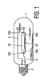
- Fig. 1 shows a metal halide lamp provided with a discharge vessel 40 having a ceramic wall which encloses a discharge space 70 containing an ionizable filling.
- First and second tungsten electrodes 105, 205 are arranged in the discharge space so as to define a discharge path between them.
- the discharge vessel is closed at either side of the discharge space by means of a first and a second closing construction of a ceramic projecting plug 130, 230 which encloses a current lead-through conductor ( Fig. 2 : 180, 280) to the respective first and second electrode 105, 205.
- the discharge vessel is surrounded by an outer bulb 1 which is provided with a lamp cap 2 at one end. A discharge will extend between the electrodes 105, 205 when the lamp is operating.
- the electrode 105 is connected via a current conductor 8 to a first electrical contact forming part of the lamp cap 2.
- the electrode 205 is connected to a second electrical contact forming part of the lamp cap 2 via a current conduct
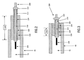
- Fig. 2 highly schematically, illustrates the seal of the second feed-through (280) of the lamp according to the invention as shown in Figure 1 .
- the lamp comprises a ceramic discharge vessel (40) into which the second closing construction, here being a projecting plug (230), is sintered.
- This plug preferably consists of the same material as the ceramic discharge vessel.
- the second closing construction (230) is co-sintered with the metal capillary tube (220), thus forming a shrink-fit sintered bond connection (260).
- the capillary tube preferably has an inner diameter of about 320 ⁇ m.
- the length of the shrink-fit sintered bond connection in Fig. 1 denoted by L sfit , should preferably be between 1 mm and 4 mm.
- Fig. 2 further shows the discharge space (70) between the first (not shown) and the second electrode (205).
- the capillary metal tube (220) is separated from the electrically conductive pin (210) by a crevice (215) of at most 10 ⁇ m width.
- the conductive pin (210), preferably having a diameter of about 300 ⁇ m, and the metal tube (220) are connected by a weld (225).
- Fig. 3 illustrates another embodiment of a second feed-through, in which the shrink-fit sintered bond connection is combined with a frit connection comprising a ceramic sealing material (250).
- the TEC of the material used for the frit connection is preferably about the average of the TECs of the metal tube and the ceramic vessel. This hybrid seal connection can be shorter than a connection with a shrink-fit sintered bond connection alone.
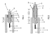
- Fig. 4 shows a further improvement of the connection in the sense that the ceramic sealing material encloses a ceramic ring (235).
- This ceramic ring is preferably of the same material as the vessel and the closing construction. With this ceramic ring, inclusion of gas pockets are avoided due to capillary forces in the gaps, with a width of not more than 50 ⁇ m, preferably not more than 30 ⁇ m between ring and vessel on the one side and ring and tube on the other side.
- a ceramic ring also prevents a high stress level from being built up in the sealing glass and in the closing construction around the frit connection.
- Fig. 5 shows a modification of the above-mentioned ceramic ring, in the sense that a ceramic sealing material (250) at least partly fills a space between the capillary tube and the second closing construction over a distance 1 frit , remote from the discharge space.
- This arrangement also allows a short sealing length.
- This embodiment has the advantage that, even if the first shrink-fit sintered bond connection does not stay vacuumtight under frequent switching conditions, the frit connection does.
- the lengths of the shrink-fit sintered bond connection (1 sfit ) and of the frit connection (1 frit ) should be chosen such that cracks in the frit connection are always avoided. Suitable lengths for the shrink-fit and the frit connection are about 2 and 2 to 4 mm respectively.
- the lamp will stay vacuumtight then, even in the case of small cracks in the shrink-fit sintered bond connection,.
- the total connection length (1 frit + 1 sfit ) should be as small as possible (short burner length), or in other words should be so small that the required lamp life and number of switching cycles are achieved. With this type of connections a lamp life of 2500-3000 h with more than 40,000 switching cycles can be obtained.
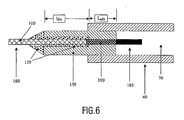
- Fig. 6 shows a possible first sealing.
- a feed-through (180) preferably consisting of 3 parts (e.g. W-Mo-Nb) is attached to the first closing construction (130), which is sintered into the ceramic discharge vessel (40).
- Part of a Mo-rod (190) adjacent to the electrode (105) has a sintered connection to the first closing construction (130) as described above.
- the remaining crevice between the Nb-rod, part of the Mo-rod, and the closing construction is filled with sealing frit (150).
- the lengths of the shrink-fit sintered connection (1 sfit ) and the frit connection (1 frit ) should be such that salt components cannot seriously attack the sealing frit, not even in the case of small cracks in the shrink-fit sintered connection.
- a length of at least 2 mm for the sealing frit is preferred to keep the temperature of the frit at a value low enough to avoid cracks caused by different shrinkages of rod and closing construction.
- the total connection length (1 frit + 1 sfit ) should be as small as possible to obtain a short length of the lamp, or in other words should be such that the required lamp life and number of switching cycles are achieved.
Landscapes
- Vessels And Coating Films For Discharge Lamps (AREA)
Claims (7)
- Hochdruckentladungslampe mit einem keramischen Entladungsgefäß (40), das einen mit einer ionisierbaren Füllung mit einem oder mehreren Halogeniden versehenen Entladungsraum einschließt, in dem eine erste (105) und eine zweite (205) Elektrode angeordnet sind und der eine erste (130) und eine zweite Schließkonstruktion (230) auf jeweiligen Seiten des Entladungsraums (70) umfasst, die mit dem Entladungsgefäß verbunden sind und eine jeweilige erste (180) und zweite Stromdurchführung (280) umfassen, wobei zumindest die zweite Durchführung (280) eine Kapillarröhre (220) umfasst, die eine gesinterte Verbindung mit der zweiten Schließkonstruktion (230) und einen in der Kapillarröhre angeordneten, elektrisch leitenden Stift (210) aufweist, wobei zwischen der Kapillarröhre und dem Stift ein Spalt (215) gelassen wird, wobei der Stift und die Kapillarröhre an einem von dem Entladungsraum entfernten Endteil zusammengeschweißt sind, dadurch gekennzeichnet, dass die Kapillarröhre einen Außendurchmesser von maximal 1 mm hat, der Spalt maximal 10 µm breit ist und der Stift und die Kapillarröhre aus einem Metall bestehen, das aus Mo, Re, W, Ir, deren Legierungen, optional auch umfassend V und/oder Ti, ausgewählt wird.
- Lampe nach Anspruch 1, wobei ein keramisches Dichtungsmaterial (250) zumindest zum Teil einen von dem Entladungsgefäß, der Kapillarröhre und der Außenseite der zweiten Schließkonstruktion eingeschlossenen Raum füllt.
- Lampe nach Anspruch 2, wobei das keramische Dichtungsmaterial einen keramischen Ring (235) einschließt.
- Lampe nach Anspruch 1, wobei ein keramisches Dichtungsmaterial (250) zumindest zum Teil einen Raum zwischen der Kapillarröhre und der zweiten Schließkonstruktion von dem Entladungsraum entfernt füllt.
- Lampe nach einem der Ansprüche 1 bis 4, wobei eine erste Stromdurchführung (180) einen ersten halogenidresistenten Leiter (190) in Angrenzung an die erste Elektrode (105) sowie einen zweiten Leiter (100), beispielsweise mit Nb, Mo, W umfasst, wobei der erste Leiter einen Durchmesser von maximal 0,5 mm und eine sich über einen Teil seiner Länge in Angrenzung an die Elektrode erstreckende, gesinterte Verbindung mit einem ersten Teil der ersten Schließkonstruktion aufweist, womit ein von dem restlichen Teil seiner Länge, dem zweiten Leiter und einem zweiten Teil der ersten Schließkonstruktion eingeschlossener Raum gelassen wird, der mit einem keramischen Dichtungsmaterial (150) gefüllt ist.
- Lampe nach Anspruch 5, wobei sich das keramische Dichtungsmaterial um den zweiten Leiter über die erste Schließkonstruktion hinaus erstreckt.
- Kraftfahrzeugscheinwerfer-Entladungslampe mit einer Lampe nach einem der Ansprüche 1 bis 6.
Priority Applications (1)
| Application Number | Priority Date | Filing Date | Title |
|---|---|---|---|
| EP05745736A EP1759403B1 (de) | 2004-06-14 | 2005-06-09 | Keramische metallhalogenid-entladungslampe |
Applications Claiming Priority (3)
| Application Number | Priority Date | Filing Date | Title |
|---|---|---|---|
| EP04102688 | 2004-06-14 | ||
| EP05745736A EP1759403B1 (de) | 2004-06-14 | 2005-06-09 | Keramische metallhalogenid-entladungslampe |
| PCT/IB2005/051895 WO2005124823A1 (en) | 2004-06-14 | 2005-06-09 | Ceramic metal halide discharge lamp |
Publications (2)
| Publication Number | Publication Date |
|---|---|
| EP1759403A1 EP1759403A1 (de) | 2007-03-07 |
| EP1759403B1 true EP1759403B1 (de) | 2012-01-25 |
Family
ID=35385335
Family Applications (1)
| Application Number | Title | Priority Date | Filing Date |
|---|---|---|---|
| EP05745736A Expired - Lifetime EP1759403B1 (de) | 2004-06-14 | 2005-06-09 | Keramische metallhalogenid-entladungslampe |
Country Status (7)
| Country | Link |
|---|---|
| US (1) | US20080284337A1 (de) |
| EP (1) | EP1759403B1 (de) |
| JP (1) | JP4772050B2 (de) |
| KR (1) | KR101120515B1 (de) |
| CN (1) | CN1969366B (de) |
| AT (1) | ATE543203T1 (de) |
| WO (1) | WO2005124823A1 (de) |
Families Citing this family (12)
| Publication number | Priority date | Publication date | Assignee | Title |
|---|---|---|---|---|
| DE102005058895A1 (de) * | 2005-12-09 | 2007-06-14 | Patent-Treuhand-Gesellschaft für elektrische Glühlampen mbH | Metallhalogenidlampe |
| JP5406028B2 (ja) | 2006-08-18 | 2014-02-05 | コーニンクレッカ フィリップス エヌ ヴェ | メタルハライドランプ |
| DE102006052761A1 (de) * | 2006-11-08 | 2008-05-15 | Patent-Treuhand-Gesellschaft für elektrische Glühlampen mbH | Keramisches Entladungsgefäß und Hochdruckentladungslampe mit einem derartigen Entladungsgefäß |
| ATE474323T1 (de) | 2006-12-18 | 2010-07-15 | Koninkl Philips Electronics Nv | Hochdruckentladungslampe mit keramischem entladungsgefäss |
| EP2122654B1 (de) * | 2006-12-20 | 2011-04-20 | Koninklijke Philips Electronics N.V. | Keramischer brenner für eine keramische metallhalogenidlampe |
| DE102007015545A1 (de) | 2007-03-30 | 2008-10-02 | Osram Gesellschaft mit beschränkter Haftung | Hochdruckentladungslampe |
| DE202007013119U1 (de) | 2007-09-19 | 2008-10-23 | Osram Gesellschaft mit beschränkter Haftung | Hochdruckentladungslampe |
| DE102007045071A1 (de) * | 2007-09-21 | 2009-04-02 | Osram Gesellschaft mit beschränkter Haftung | Hochdrucklampe und zugehöriges Betriebsverfahren für den Resonanzbetrieb von Hochdrucklampen im longitudinalen Mode und zugehöriges System |
| KR101014534B1 (ko) * | 2008-08-26 | 2011-02-14 | 성균관대학교산학협력단 | 과도특성 모델링을 위한 장치 및 방법 |
| JP5597852B2 (ja) * | 2009-09-14 | 2014-10-01 | 東京瓦斯株式会社 | 水素分離膜及び水素分離法 |
| DE112011104641A5 (de) | 2011-05-17 | 2013-10-02 | Osram Gmbh | Hochdruckentladungslampe |
| WO2014012575A1 (de) | 2012-07-16 | 2014-01-23 | Osram Gmbh | Hochdruckentladungslampe mit glaslotgedichteter durchführung |
Family Cites Families (28)
| Publication number | Priority date | Publication date | Assignee | Title |
|---|---|---|---|---|
| NL174683C (nl) * | 1975-09-11 | 1984-07-16 | Philips Nv | Hogedrukgasontladingslamp. |
| US4545799A (en) * | 1983-09-06 | 1985-10-08 | Gte Laboratories Incorporated | Method of making direct seal between niobium and ceramics |
| EP0187401A1 (de) * | 1984-12-18 | 1986-07-16 | Koninklijke Philips Electronics N.V. | Hochdruckentladungslampe |
| DE3636110A1 (de) * | 1986-10-23 | 1988-04-28 | Patent Treuhand Ges Fuer Elektrische Gluehlampen Mbh | Einschmelzung fuer eine hochdruckentladungslampe |
| US5404078A (en) * | 1991-08-20 | 1995-04-04 | Patent-Treuhand-Gesellschaft Fur Elektrische Gluhlampen Mbh | High-pressure discharge lamp and method of manufacture |
| US5434472A (en) * | 1992-04-15 | 1995-07-18 | United States Philips Corporation | High-pressure sodium discharge lamp with getter |
| US5424609A (en) * | 1992-09-08 | 1995-06-13 | U.S. Philips Corporation | High-pressure discharge lamp |
| EP0587238B1 (de) * | 1992-09-08 | 2000-07-19 | Koninklijke Philips Electronics N.V. | Hochdruckentladungslampe |
| EP0592040B1 (de) * | 1992-10-08 | 1999-01-13 | Koninklijke Philips Electronics N.V. | Hochdruckentladungslampe |
| DE4242122A1 (de) * | 1992-12-14 | 1994-06-16 | Patent Treuhand Ges Fuer Elektrische Gluehlampen Mbh | Verfahren zur Herstellung einer vakuumdichten Abdichtung zwischen einem keramischen und einem metallischen Partner, insbesondere zur Anwendung bei der Herstellung eines Entladungsgefäßes für eine Lampe, sowie damit hergestellte Entladungsgefäße und Lampen |
| EP0609477B1 (de) * | 1993-02-05 | 1999-05-06 | Patent-Treuhand-Gesellschaft für elektrische Glühlampen mbH | Keramisches Entladungsgefäss für Hochdruckentladungslampe und Herstellungsverfahren derselben und damit verbundene Dichtungsmaterialien |
| WO1996028839A1 (en) * | 1995-03-09 | 1996-09-19 | Philips Electronics N.V. | High-pressure discharge lamp |
| DE19727429A1 (de) * | 1997-06-27 | 1999-01-07 | Patent Treuhand Ges Fuer Elektrische Gluehlampen Mbh | Metallhalogenidlampe mit keramischem Entladungsgefäß |
| JPH11283569A (ja) * | 1998-03-30 | 1999-10-15 | Ngk Insulators Ltd | 高圧放電灯 |
| JP2000021350A (ja) * | 1998-06-30 | 2000-01-21 | Ushio Inc | セラミック製放電ランプ |
| JP2000090882A (ja) * | 1998-09-11 | 2000-03-31 | Toshiba Lighting & Technology Corp | 高圧放電ランプおよび照明装置 |
| JP2000228170A (ja) * | 1998-12-04 | 2000-08-15 | Toshiba Lighting & Technology Corp | 高圧放電ランプ、高圧放電ランプ装置、高圧放電ランプ点灯装置および照明装置 |
| JP2003508884A (ja) * | 1999-08-31 | 2003-03-04 | コーニンクレッカ フィリップス エレクトロニクス エヌ ヴィ | メタルハライドランプ |
| DE10026802A1 (de) * | 2000-05-31 | 2002-01-03 | Patent Treuhand Ges Fuer Elektrische Gluehlampen Mbh | Metallhalogenidlampe mit keramischem Entladungsgefäß |
| JP4379552B2 (ja) * | 2000-05-31 | 2009-12-09 | 東芝ライテック株式会社 | 高圧放電ランプおよび照明装置 |
| US20020033670A1 (en) * | 2000-07-03 | 2002-03-21 | Ngk Insulators, Ltd. | Joined body and a high pressure discharge lamp |
| EP1205963B1 (de) * | 2000-11-07 | 2012-01-18 | Panasonic Corporation | Hochdruckentladungslampe und Bogenröhre |
| US6791267B2 (en) * | 2001-10-02 | 2004-09-14 | Ngk Insulators, Ltd. | High pressure discharge lamps, lighting systems, head lamps for automobiles and light emitting vessels for high pressure discharge lamps |
| US6713962B2 (en) * | 2001-10-17 | 2004-03-30 | Matsushita Electric Industrial Co., Ltd. | High-pressure discharge lamp |
| JP2003297289A (ja) * | 2002-01-30 | 2003-10-17 | Toshiba Lighting & Technology Corp | 高圧放電ランプおよび多重管形高圧放電ランプならびに照明装置 |
| US6856091B2 (en) * | 2002-06-24 | 2005-02-15 | Matsushita Electric Industrial Co., Ltd. | Seal for ceramic metal halide discharge lamp chamber |
| US7839089B2 (en) * | 2002-12-18 | 2010-11-23 | General Electric Company | Hermetical lamp sealing techniques and lamp having uniquely sealed components |
| JP4229437B2 (ja) * | 2003-06-05 | 2009-02-25 | 株式会社小糸製作所 | 自動車用放電バルブおよび自動車前照灯 |
-
2005
- 2005-06-09 WO PCT/IB2005/051895 patent/WO2005124823A1/en not_active Ceased
- 2005-06-09 EP EP05745736A patent/EP1759403B1/de not_active Expired - Lifetime
- 2005-06-09 CN CN2005800195102A patent/CN1969366B/zh not_active Expired - Fee Related
- 2005-06-09 AT AT05745736T patent/ATE543203T1/de active
- 2005-06-09 KR KR1020077000790A patent/KR101120515B1/ko not_active Expired - Fee Related
- 2005-06-09 JP JP2007526656A patent/JP4772050B2/ja not_active Expired - Fee Related
- 2005-06-09 US US11/570,348 patent/US20080284337A1/en not_active Abandoned
Also Published As
| Publication number | Publication date |
|---|---|
| CN1969366A (zh) | 2007-05-23 |
| KR20070032008A (ko) | 2007-03-20 |
| WO2005124823A1 (en) | 2005-12-29 |
| KR101120515B1 (ko) | 2012-02-29 |
| ATE543203T1 (de) | 2012-02-15 |
| EP1759403A1 (de) | 2007-03-07 |
| JP4772050B2 (ja) | 2011-09-14 |
| JP2008503063A (ja) | 2008-01-31 |
| US20080284337A1 (en) | 2008-11-20 |
| CN1969366B (zh) | 2011-06-08 |
Similar Documents
| Publication | Publication Date | Title |
|---|---|---|
| US5404078A (en) | High-pressure discharge lamp and method of manufacture | |
| EP0887837B1 (de) | Keramischer Kolben, Lampe mit einem solchen Kolben und Verfahren zur Herstellung solchen Vorrichtungen | |
| EP0751549B1 (de) | Hochdruckentladungslampe und ihr herstellungsverfahren | |
| JP4304902B2 (ja) | 高圧放電ランプ | |
| US6873108B2 (en) | Monolithic seal for a sapphire metal halide lamp | |
| US4160930A (en) | Electric discharge lamp with annular current conductor | |
| US20080284337A1 (en) | Ceramic Metal Halide Discharge Lamp | |
| JP2008124037A (ja) | 高圧放電ランプ | |
| EP2122663B1 (de) | Hochdruckentladungslampe mit keramischem entladungsgefäss | |
| GB2366908A (en) | Metal halide lamp with ceramic discharge vessel | |
| EP1146537A1 (de) | Hochdruckbogenentladungslampenröhre und deren herstellungsverfahren | |
| US8310157B2 (en) | Lamp having metal conductor bonded to ceramic leg member | |
| CA2205327C (en) | Electrode assembly for high pressure sodium lamp and method of making same | |
| JP2011151027A (ja) | 放電ランプ用セラミック発光管においてフリットレスシールを作製する方法 | |
| JP2006244736A (ja) | 高圧放電ランプ |
Legal Events
| Date | Code | Title | Description |
|---|---|---|---|
| PUAI | Public reference made under article 153(3) epc to a published international application that has entered the european phase |
Free format text: ORIGINAL CODE: 0009012 |
|
| 17P | Request for examination filed |
Effective date: 20070115 |
|
| AK | Designated contracting states |
Kind code of ref document: A1 Designated state(s): AT BE BG CH CY CZ DE DK EE ES FI FR GB GR HU IE IS IT LI LT LU MC NL PL PT RO SE SI SK TR |
|
| DAX | Request for extension of the european patent (deleted) | ||
| 17Q | First examination report despatched |
Effective date: 20091217 |
|
| GRAP | Despatch of communication of intention to grant a patent |
Free format text: ORIGINAL CODE: EPIDOSNIGR1 |
|
| GRAS | Grant fee paid |
Free format text: ORIGINAL CODE: EPIDOSNIGR3 |
|
| GRAA | (expected) grant |
Free format text: ORIGINAL CODE: 0009210 |
|
| AK | Designated contracting states |
Kind code of ref document: B1 Designated state(s): AT BE BG CH CY CZ DE DK EE ES FI FR GB GR HU IE IS IT LI LT LU MC NL PL PT RO SE SI SK TR |
|
| REG | Reference to a national code |
Ref country code: GB Ref legal event code: FG4D |
|
| REG | Reference to a national code |
Ref country code: CH Ref legal event code: EP |
|
| REG | Reference to a national code |
Ref country code: AT Ref legal event code: REF Ref document number: 543203 Country of ref document: AT Kind code of ref document: T Effective date: 20120215 |
|
| REG | Reference to a national code |
Ref country code: IE Ref legal event code: FG4D |
|
| REG | Reference to a national code |
Ref country code: DE Ref legal event code: R096 Ref document number: 602005032392 Country of ref document: DE Effective date: 20120322 |
|
| REG | Reference to a national code |
Ref country code: DE Ref legal event code: R084 Ref document number: 602005032392 Country of ref document: DE Effective date: 20120204 |
|
| REG | Reference to a national code |
Ref country code: GB Ref legal event code: 746 Effective date: 20120319 |
|
| REG | Reference to a national code |
Ref country code: NL Ref legal event code: VDEP Effective date: 20120125 |
|
| LTIE | Lt: invalidation of european patent or patent extension |
Effective date: 20120125 |
|
| PG25 | Lapsed in a contracting state [announced via postgrant information from national office to epo] |
Ref country code: NL Free format text: LAPSE BECAUSE OF FAILURE TO SUBMIT A TRANSLATION OF THE DESCRIPTION OR TO PAY THE FEE WITHIN THE PRESCRIBED TIME-LIMIT Effective date: 20120125 Ref country code: LT Free format text: LAPSE BECAUSE OF FAILURE TO SUBMIT A TRANSLATION OF THE DESCRIPTION OR TO PAY THE FEE WITHIN THE PRESCRIBED TIME-LIMIT Effective date: 20120125 Ref country code: BG Free format text: LAPSE BECAUSE OF FAILURE TO SUBMIT A TRANSLATION OF THE DESCRIPTION OR TO PAY THE FEE WITHIN THE PRESCRIBED TIME-LIMIT Effective date: 20120425 Ref country code: IS Free format text: LAPSE BECAUSE OF FAILURE TO SUBMIT A TRANSLATION OF THE DESCRIPTION OR TO PAY THE FEE WITHIN THE PRESCRIBED TIME-LIMIT Effective date: 20120525 Ref country code: BE Free format text: LAPSE BECAUSE OF FAILURE TO SUBMIT A TRANSLATION OF THE DESCRIPTION OR TO PAY THE FEE WITHIN THE PRESCRIBED TIME-LIMIT Effective date: 20120125 |
|
| PG25 | Lapsed in a contracting state [announced via postgrant information from national office to epo] |
Ref country code: PT Free format text: LAPSE BECAUSE OF FAILURE TO SUBMIT A TRANSLATION OF THE DESCRIPTION OR TO PAY THE FEE WITHIN THE PRESCRIBED TIME-LIMIT Effective date: 20120525 Ref country code: PL Free format text: LAPSE BECAUSE OF FAILURE TO SUBMIT A TRANSLATION OF THE DESCRIPTION OR TO PAY THE FEE WITHIN THE PRESCRIBED TIME-LIMIT Effective date: 20120125 Ref country code: FI Free format text: LAPSE BECAUSE OF FAILURE TO SUBMIT A TRANSLATION OF THE DESCRIPTION OR TO PAY THE FEE WITHIN THE PRESCRIBED TIME-LIMIT Effective date: 20120125 Ref country code: GR Free format text: LAPSE BECAUSE OF FAILURE TO SUBMIT A TRANSLATION OF THE DESCRIPTION OR TO PAY THE FEE WITHIN THE PRESCRIBED TIME-LIMIT Effective date: 20120426 |
|
| PGFP | Annual fee paid to national office [announced via postgrant information from national office to epo] |
Ref country code: GB Payment date: 20120629 Year of fee payment: 8 |
|
| REG | Reference to a national code |
Ref country code: AT Ref legal event code: MK05 Ref document number: 543203 Country of ref document: AT Kind code of ref document: T Effective date: 20120125 |
|
| PG25 | Lapsed in a contracting state [announced via postgrant information from national office to epo] |
Ref country code: CY Free format text: LAPSE BECAUSE OF FAILURE TO SUBMIT A TRANSLATION OF THE DESCRIPTION OR TO PAY THE FEE WITHIN THE PRESCRIBED TIME-LIMIT Effective date: 20120125 |
|
| PG25 | Lapsed in a contracting state [announced via postgrant information from national office to epo] |
Ref country code: SI Free format text: LAPSE BECAUSE OF FAILURE TO SUBMIT A TRANSLATION OF THE DESCRIPTION OR TO PAY THE FEE WITHIN THE PRESCRIBED TIME-LIMIT Effective date: 20120125 Ref country code: DK Free format text: LAPSE BECAUSE OF FAILURE TO SUBMIT A TRANSLATION OF THE DESCRIPTION OR TO PAY THE FEE WITHIN THE PRESCRIBED TIME-LIMIT Effective date: 20120125 Ref country code: SE Free format text: LAPSE BECAUSE OF FAILURE TO SUBMIT A TRANSLATION OF THE DESCRIPTION OR TO PAY THE FEE WITHIN THE PRESCRIBED TIME-LIMIT Effective date: 20120125 Ref country code: RO Free format text: LAPSE BECAUSE OF FAILURE TO SUBMIT A TRANSLATION OF THE DESCRIPTION OR TO PAY THE FEE WITHIN THE PRESCRIBED TIME-LIMIT Effective date: 20120125 Ref country code: CZ Free format text: LAPSE BECAUSE OF FAILURE TO SUBMIT A TRANSLATION OF THE DESCRIPTION OR TO PAY THE FEE WITHIN THE PRESCRIBED TIME-LIMIT Effective date: 20120125 Ref country code: EE Free format text: LAPSE BECAUSE OF FAILURE TO SUBMIT A TRANSLATION OF THE DESCRIPTION OR TO PAY THE FEE WITHIN THE PRESCRIBED TIME-LIMIT Effective date: 20120125 |
|
| PG25 | Lapsed in a contracting state [announced via postgrant information from national office to epo] |
Ref country code: IT Free format text: LAPSE BECAUSE OF FAILURE TO SUBMIT A TRANSLATION OF THE DESCRIPTION OR TO PAY THE FEE WITHIN THE PRESCRIBED TIME-LIMIT Effective date: 20120125 Ref country code: SK Free format text: LAPSE BECAUSE OF FAILURE TO SUBMIT A TRANSLATION OF THE DESCRIPTION OR TO PAY THE FEE WITHIN THE PRESCRIBED TIME-LIMIT Effective date: 20120125 |
|
| PLBE | No opposition filed within time limit |
Free format text: ORIGINAL CODE: 0009261 |
|
| STAA | Information on the status of an ep patent application or granted ep patent |
Free format text: STATUS: NO OPPOSITION FILED WITHIN TIME LIMIT |
|
| PGFP | Annual fee paid to national office [announced via postgrant information from national office to epo] |
Ref country code: FR Payment date: 20120717 Year of fee payment: 8 Ref country code: DE Payment date: 20120830 Year of fee payment: 8 |
|
| 26N | No opposition filed |
Effective date: 20121026 |
|
| PG25 | Lapsed in a contracting state [announced via postgrant information from national office to epo] |
Ref country code: MC Free format text: LAPSE BECAUSE OF NON-PAYMENT OF DUE FEES Effective date: 20120630 Ref country code: AT Free format text: LAPSE BECAUSE OF FAILURE TO SUBMIT A TRANSLATION OF THE DESCRIPTION OR TO PAY THE FEE WITHIN THE PRESCRIBED TIME-LIMIT Effective date: 20120125 |
|
| REG | Reference to a national code |
Ref country code: CH Ref legal event code: PL |
|
| REG | Reference to a national code |
Ref country code: CH Ref legal event code: PL |
|
| REG | Reference to a national code |
Ref country code: DE Ref legal event code: R097 Ref document number: 602005032392 Country of ref document: DE Effective date: 20121026 |
|
| REG | Reference to a national code |
Ref country code: IE Ref legal event code: MM4A |
|
| PG25 | Lapsed in a contracting state [announced via postgrant information from national office to epo] |
Ref country code: LI Free format text: LAPSE BECAUSE OF NON-PAYMENT OF DUE FEES Effective date: 20120630 Ref country code: IE Free format text: LAPSE BECAUSE OF NON-PAYMENT OF DUE FEES Effective date: 20120609 Ref country code: CH Free format text: LAPSE BECAUSE OF NON-PAYMENT OF DUE FEES Effective date: 20120630 Ref country code: ES Free format text: LAPSE BECAUSE OF FAILURE TO SUBMIT A TRANSLATION OF THE DESCRIPTION OR TO PAY THE FEE WITHIN THE PRESCRIBED TIME-LIMIT Effective date: 20120506 |
|
| GBPC | Gb: european patent ceased through non-payment of renewal fee |
Effective date: 20130609 |
|
| REG | Reference to a national code |
Ref country code: DE Ref legal event code: R119 Ref document number: 602005032392 Country of ref document: DE Effective date: 20140101 |
|
| REG | Reference to a national code |
Ref country code: FR Ref legal event code: ST Effective date: 20140228 |
|
| PG25 | Lapsed in a contracting state [announced via postgrant information from national office to epo] |
Ref country code: TR Free format text: LAPSE BECAUSE OF FAILURE TO SUBMIT A TRANSLATION OF THE DESCRIPTION OR TO PAY THE FEE WITHIN THE PRESCRIBED TIME-LIMIT Effective date: 20120125 Ref country code: DE Free format text: LAPSE BECAUSE OF NON-PAYMENT OF DUE FEES Effective date: 20140101 Ref country code: GB Free format text: LAPSE BECAUSE OF NON-PAYMENT OF DUE FEES Effective date: 20130609 |
|
| PG25 | Lapsed in a contracting state [announced via postgrant information from national office to epo] |
Ref country code: FR Free format text: LAPSE BECAUSE OF NON-PAYMENT OF DUE FEES Effective date: 20130701 Ref country code: LU Free format text: LAPSE BECAUSE OF NON-PAYMENT OF DUE FEES Effective date: 20120609 |
|
| PG25 | Lapsed in a contracting state [announced via postgrant information from national office to epo] |
Ref country code: HU Free format text: LAPSE BECAUSE OF FAILURE TO SUBMIT A TRANSLATION OF THE DESCRIPTION OR TO PAY THE FEE WITHIN THE PRESCRIBED TIME-LIMIT Effective date: 20050609 |