EP1759629B1 - Endoscope a direction de visée variable - Google Patents
Endoscope a direction de visée variable Download PDFInfo
- Publication number
- EP1759629B1 EP1759629B1 EP05018933.1A EP05018933A EP1759629B1 EP 1759629 B1 EP1759629 B1 EP 1759629B1 EP 05018933 A EP05018933 A EP 05018933A EP 1759629 B1 EP1759629 B1 EP 1759629B1
- Authority
- EP
- European Patent Office
- Prior art keywords
- endoscope
- shaft
- pivot axis
- optical imaging
- imaging system
- Prior art date
- Legal status (The legal status is an assumption and is not a legal conclusion. Google has not performed a legal analysis and makes no representation as to the accuracy of the status listed.)
- Expired - Lifetime
Links
Images


Classifications
-
- G—PHYSICS
- G02—OPTICS
- G02B—OPTICAL ELEMENTS, SYSTEMS OR APPARATUS
- G02B23/00—Telescopes, e.g. binoculars; Periscopes; Instruments for viewing the inside of hollow bodies; Viewfinders; Optical aiming or sighting devices
- G02B23/24—Instruments or systems for viewing the inside of hollow bodies, e.g. fibrescopes
- G02B23/2476—Non-optical details, e.g. housings, mountings, supports
- G02B23/2484—Arrangements in relation to a camera or imaging device
-
- A—HUMAN NECESSITIES
- A61—MEDICAL OR VETERINARY SCIENCE; HYGIENE
- A61B—DIAGNOSIS; SURGERY; IDENTIFICATION
- A61B1/00—Instruments for performing medical examinations of the interior of cavities or tubes of the body by visual or photographical inspection, e.g. endoscopes; Illuminating arrangements therefor
- A61B1/00163—Optical arrangements
- A61B1/00174—Optical arrangements characterised by the viewing angles
- A61B1/00179—Optical arrangements characterised by the viewing angles for off-axis viewing
-
- A—HUMAN NECESSITIES
- A61—MEDICAL OR VETERINARY SCIENCE; HYGIENE
- A61B—DIAGNOSIS; SURGERY; IDENTIFICATION
- A61B1/00—Instruments for performing medical examinations of the interior of cavities or tubes of the body by visual or photographical inspection, e.g. endoscopes; Illuminating arrangements therefor
- A61B1/00163—Optical arrangements
- A61B1/00174—Optical arrangements characterised by the viewing angles
- A61B1/00183—Optical arrangements characterised by the viewing angles for variable viewing angles
-
- A—HUMAN NECESSITIES
- A61—MEDICAL OR VETERINARY SCIENCE; HYGIENE
- A61B—DIAGNOSIS; SURGERY; IDENTIFICATION
- A61B1/00—Instruments for performing medical examinations of the interior of cavities or tubes of the body by visual or photographical inspection, e.g. endoscopes; Illuminating arrangements therefor
- A61B1/04—Instruments for performing medical examinations of the interior of cavities or tubes of the body by visual or photographical inspection, e.g. endoscopes; Illuminating arrangements therefor combined with photographic or television appliances
- A61B1/05—Instruments for performing medical examinations of the interior of cavities or tubes of the body by visual or photographical inspection, e.g. endoscopes; Illuminating arrangements therefor combined with photographic or television appliances characterised by the image sensor, e.g. camera, being in the distal end portion
-
- H—ELECTRICITY
- H04—ELECTRIC COMMUNICATION TECHNIQUE
- H04N—PICTORIAL COMMUNICATION, e.g. TELEVISION
- H04N23/00—Cameras or camera modules comprising electronic image sensors; Control thereof
- H04N23/50—Constructional details
- H04N23/555—Constructional details for picking-up images in sites, inaccessible due to their dimensions or hazardous conditions, e.g. endoscopes or borescopes
Definitions
- the invention relates to an endoscope, comprising an elongated rigid shaft and an optical imaging system arranged at a substantially rigid distal end of the shaft for receiving light from an observation area, wherein the optical imaging system is pivotable with respect to the shaft about a first pivot axis which runs about transversely to a longitudinal axis of the shaft, wherein the optical imaging system is at least partially arranged in a distal head which is pivotably mounted on a first rigid shaft portion to be pivotable about the first pivot axis.
- Endoscopes are used for medical, in particular surgical purposes and for industrial purposes.
- endoscopes are used in minimally-invasive surgery, such as laparoscopic, hysteroscopic, and arthroscopic surgery which is becoming more widely used because it is often less traumatic to the patient. Endoscopes are not only utilized for surgical procedures, but are also utilized as a pure observation instrument for assisting a physician to accurately place medical equipment into a body cavity.
- endoscopes are, for example, used to inspect cavities in machines or machine parts, or they are used to observe dynamic processes in, for example, internal combustion engines.
- the present invention is applicable to endoscopes for medical purposes as well as for endoscopes for industrial purposes.
- an endoscope enables a person to remotely view an observation area.
- an endoscope comprises an optical imaging system arranged at a distal end of the shaft for receiving light from the observation area.
- the optical imaging system typically comprises an objective lens arrangement or light entrance window which determines the direction of view of the endoscope.
- the optical imaging system can further comprise an electronic image pick-up, for example a charged coupled device (CCD) chip, which is also arranged at the distal end of the endoscope shaft proximally to the objective lens arrangement.
- CCD charged coupled device
- the endoscope known from the above-mentioned document US 2003/0032863 A1 has an elongated rigid shaft provided at the distal end thereof with an optical imaging system which is supported on a mobile head.
- the mobile head and, thus, the optical imaging system is pivotable with respect to the shaft about a pivot axis which runs about transversely to a longitudinal axis of the shaft, allowing for a pivot range for the optical imaging system of more than 90° about the single pivot axis.
- the direction of view of the optical imaging system lies on the longitudinal axis of the shaft, thus allowing a straight ahead view.
- the mobile head can be pivoted about the pivot axis in one plane which includes the longitudinal axis of the shaft.
- a drawback of this known endoscope is that the mobile head is pivotable about the pivot axis by an angle of about 90° at most.
- this known endoscope is not suited to allow directions of view which are directed backward with respect to the distal end of the endoscope shaft.
- it is, therefore, necessary to draw the endoscope back or to replace the endoscope with an endoscope for backward viewing.
- such a displacement or replacement of the endoscope can be undesirable.
- US 2003/0092966 A1 Another endoscope having a variable direction of view is disclosed in US 2003/0092966 A1 .
- This known endoscope comprises a rigid shaft having a glass housing mounted at the distal end of the shaft and which is arranged off-axis with respect to the longitudinal axis of the shaft.
- An optical imaging system is arranged in the housing.
- the optical imaging system can be rotated about a rotation axis perpendicular to the longitudinal axis of the shaft.
- this design renders it possible to adjust a direction of view in 180° (backward) direction with respect to the longitudinal axis
- this design has the drawback that the line of sight in 0° direction is offset with respect to the longitudinal axis of the shaft.
- Such an offset between the line of sight in 0° direction and the longitudinal axis requires a certain habituation to the use of this known endoscope.
- US 6,371,909 B1 discloses a variable direction-of-view endoscope.
- the endoscope comprises an optical imaging system at the distal end of the endoscope shaft, wherein the optical imaging system is pivotable about a pivot axis which runs about transversely to the longitudinal axis of the shaft. Nevertheless, the pivoting movement of the optical imaging system is limited to angles of view in the range from 0° to about ⁇ 150°.
- endoscopes having a flexible shaft rather than a rigid shaft, as, for example, described in US-A-5 179 934 or US 2001/0023313 A1 .
- Such flexible endoscopes usually have a control mechanism for bending the distal region of the flexible shaft, and by virtue of the flexibility of the shaft allow angles of view in a plane in the range from 0° to 180°.
- the control mechanism of such flexible endoscopes consists of a pullwire mechanism which is cost-intensive in terms of manufacture.
- a conventional flexible endoscope needs space in the distal region when the distal end of the shaft is bended back. This is because the bending radius cannot be made as small as desired due to glass fibers used for the imaging system of such a flexible endoscope.
- an object of the present invention to improve an endoscope as mentioned at the outset in such a way that the range of possible angles of view is enlarged without increasing the space needed in the observation area for the increased range of directions of view.
- this object is achieved with respect to the endoscope mentioned at the outset in that the optical imaging system is pivotable with respect to the shaft about at least a second pivot axis, which is spaced from the first pivot axis and runs about transversely to the longitudinal axis of the shaft, that an overall pivot range of the optical imaging system about the first and at least second pivot axis is at least 150° from the longitudinal axis of the shaft, and that the first shaft portion is pivotably mounted on a second rigid shaft portion to be pivotable about the at least one second pivot axis, and that the distal head has a substantially ball-shaped housing, wherein the first pivot axis substantially runs through the center of the ball-shaped housing.
- the endoscope according to the present invention has at least two well defined pivot axes which are spaced from one another in the longitudinal direction of the shaft and about which the optical imaging system can be pivoted such that the single pivot ranges of the optical imaging system about the first and second pivot axis add up to an overall pivot range which is larger than the single pivot ranges themselves.
- the provision of the at least one second pivot axis in a distance from the third pivot axis renders it possible to achieve directions of view even in the range from 0° to about 180° or more, and further ensures that the 0° direction of view is aligned with the longitudinal axis of the shaft, i.e. is not offset with respect to same.
- an enhanced range of angles of view can be achieved with the present invention.
- the present invention can be used in endoscopes having a rigid shaft as well as in endoscopes having a semi-flexible or flexible shaft, where it is advantageous that the change of direction of view is no longer based on a bending action, but on a pivoting movement about two well defined fixed pivot axes.
- the distal region of the endoscope according to the invention comprises at least three parts which are articulatedly connected to one another.
- the joints between the distal head, the first shaft portion and the second shaft portion can advantageously be formed by pins or the like in order to obtain defined first and at least one second pivot axes without the need for flexible elements which could be too weak to withstand a large number of bending operations.
- the distal head has a substantially ball-shaped housing.
- the distal head which forms the outermost distal end of the endoscope does not represent edges or the like and, therefore, does not cause the risk of tissue damages in case the endoscope according to the invention is used as a medical endoscope for observing a body cavity, when the optical imaging system is pivoted about the first and/or at least one second pivot axis.
- the overall pivot range is at least about 180° from the longitudinal axis of the shaft.
- the advantage of this measure is that a backward view direction substantially parallel to the longitudinal axis of the shaft can be obtained. Thus, it is possible to observe the backside of a structure in a recess of the observation area.
- the optical imaging system is pivotable about the first and/or at least one second pivot axis from the longitudinal axis in opposite directions.
- the advantage here is that the overall pivot range of the optical imaging system about the first and at least one second pivot axis is still increased, for example in connection with the refinement mentioned before an overall pivot range of ⁇ 180° can be achieved.
- the optical imaging system is pivotable about the first pivot axis in a range of at least about 70° to about 110° and about the at least one second pivot axis in a range of at least about 40° to about 110°.
- the pivot ranges of the optical imaging system about the first and at least one second pivot axis add up to an overall pivot, range of at least 150° from the longitudinal axis of the shaft.
- the pivot range about the first pivot axis and the at least one second pivot axis is approximately at least 90° in each case.
- first pivot axis and the at least one second pivot axis are about parallel with respect to one another.
- the advantage of this measure is that the overall range of directions of view lie in the same plane when the optical imaging system is pivoted about the first pivot axis and additionally about the second pivot axis. Thus, when the optical imaging system is pivoted about the first pivot axis and then about the second pivot axis, the line of sight is swept through the same plane.
- the optical imaging system comprises an electronic image pick-up and an imaging optics for imaging an object to be viewed onto the image pick-up, the image pick-up and the imaging optics being arranged in the distal head.
- the advantage of this measure is that the entire optical imaging system is arranged in the distal head and is pivoted about the first pivot axis and the at least one second pivot axis as a whole, thus avoiding complicated optical arrangements in order to pass the light through the pivotable regions of the endoscope according to different pivot angles about the first and/or at least one second pivot axis.
- the signal transfer from the image pick-up to the proximal region to the endoscope can be more preferably realized by means of sliding contacts or still more preferably with the aid of radio signals produced by the image pick-up.
- transponder technique can be used in order to realize a transmission of the image pick-up signals to the proximal region of the endoscope.
- One or more receiver coils can be arranged in the distal head for receiving inductively coupled-in energy and control signals, and a transmission system which transmits image signals from the image pick-up outwards for further processing.
- the optical imaging system is rotatable about the longitudinal axis of the shaft.
- This measure is in particular advantageous, because the overall range of directions of view is still increased without the need to rotate the endoscope about the longitudinal axis of the shaft.
- the optical imaging system and thus the direction of view can be swept through nearly the entire solid angle of 4 ⁇ , if, as provided in a further preferred refinement, the range of rotation of the optical imaging system about the longitudinal axis of the shaft is about 360°.
- the second shaft portion is rotatable with respect to a stationary portion of the shaft.
- the rotary movement is achieved in a manner which is advantageously simple in construction by the fact, that the second shaft portion when rotated relative to the stationary shaft portion entrains the first shaft portion, the distal head and thereby the optical imaging system.
- a control mechanism is provided to control the pivoting movement of the optical imaging system about the first and/or the at least one second pivot axis.
- control mechanism is that the single movements of the optical imaging system about the first and/or at least one second pivot axis and, if provided, about the longitudinal axis of the shaft, can be controlled by the user of the endoscope on demand as the need arises.
- control mechanism is configured such that it can control the pivoting movement of the optical imaging system about the first pivot axis independently from the pivoting movement about the at least one second pivot axis and vice versa.
- the advantage of this measure is that in cases where only a change of the direction of view in a small angle range, for example in an angle range of less than 90° from the longitudinal axis as required, it is sufficient to pivot the optical imaging system about the first pivot axis, without the need to additionally pivot the optical imaging system about the at least one second pivot axis.
- This can be advantageous, if the observation area is very narrow and not much wider than the outer diameter of the distal end of the endoscope shaft where the optical imaging system is arranged, because the pivoting movement of the optical imaging system about the first pivot axis does not require an additional lateral space, while such additional lateral space is necessary for a pivoting movement of the optical imaging system about the second pivot axis.
- control mechanism comprises at least one gear having a first wheel which meshes with a second wheel fixed to the distal head.
- control mechanism comprises a belt drive in order to pivot the distal head relative to the first shaft portion.
- control mechanism comprises at least an electric motor for driving the gear or the belt drive mentioned before.
- control mechanism comprises a gear or belt drive to control the pivoting movement of the first shaft portion with respect to the second shaft portion
- the control mechanism comprises at least an electric motor to drive the gear or the belt drive for pivoting the first shaft portion with respect to the second shaft portion.
- control mechanism comprises a gear to control the rotating movement of the second shaft portion with respect to the stationary portion of the shaft, and, if the control mechanism comprises at least an electric motor for driving the gear for rotating the second shaft portion with respect to the remainder of the shaft.
- control mechanism for pivoting the optical imaging system about the first and/or at least one second pivot axis and/or for rotating it about the longitudinal axis of the shaft can be magnetic, pneumatic, hydraulic control mechanisms, or control mechanisms, which act just mechanically such as via pull- and push rods.
- distal head containing the optical imaging system can be supported in magnetic bearings, air cushion bearings or the like.
- the one or more electric motors mentioned before in connection with the control mechanism preferably is or are a step motor.
- step motor is that also very small movements of the optical imaging system can be controlled in a very fine and precise manner.
- the endoscope according to the invention further comprises an illuminating system for transmitting light into the observation area, the illuminating system being pivotable about the first and at least one second pivot axis together with the optical imaging system.
- the advantage of this measure is, that the illuminating system always follows the movement of the optical imaging system, thus ensuring that the region of the observation area which is actually observed, is always sufficiently illuminated.
- the illuminating system comprises a light source having at least one light emitting diode (LED) arranged adjacent the optical imaging system, and/or if the illuminating system comprises a light source configured as a ring or at least as a partial ring surrounding or at least partially surrounding a light entrance window of the optical imaging system.
- LED light emitting diode
- the ring shaped illuminating system can be comprised of a plurality of adjacent LED's or of a single LED in ring shape.
- Such LED light sources are obtainable in miniaturized size, and, therefore, are very suited as illuminating system for the endoscope according to the invention.
- the endoscope 10 can be an endoscope for medical purposes or an endoscope for industrial purposes.
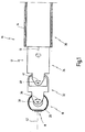
- the endoscope 10 comprises an elongated shaft 12 having a longitudinal axis 13. At least a distal end of the shaft 12 is rigid. As illustrated in Fig. 8 and 1 , shaft 12 comprises an outer shaft 14 which extends to a proximal end (not shown) of the endoscope.
- the outer shaft 14 is a stationary portion of the shaft 12, as will be described in more detail below. Only for the reason of simplicity of illustration, the outer shaft 14 has been shown as transparent part, while in practical cases, the outer shaft 14 is made of steel, for example.
- the distal end of the endoscope 10 comprises a rigid distal head 16 which comprises or contains an optical imaging system 18, which is illustrated in more detail in Fig. 3 .
- the optical imaging system 18 comprises an imaging optics 22 which is configured in the illustrated embodiment as an objective lens with imaging capabilities.
- the optical imaging system 18 further comprises an electronic image pick-up 24, which is configured in the present embodiment as a CCD-chip.
- An aperture stop 26 is arranged between the imaging optics 22 and the image pick-up 24.
- the imaging optics 22, the image pick-up 24 and the aperture stop 26 form a miniaturized video camera which is completely incorporated in the distal head 16 of the endoscope 10.
- the distal head 16 comprises a substantially ball-shaped housing 20 for housing the imaging optics 22, the aperture stop 26 and the image pick-up 24.
- one or more receiver coils can be arranged in the distal head for receiving inductively coupled-in energy and control signals, and a transmission system which transmits image signals from the image pick-up outwards for further processing.
- the endoscope 10 comprises an illuminating system 28 which is also arranged in the distal head 16.
- the illuminating system 28 comprises a light source 30 configured as a ring which surrounds a light entrance window 29 of the optical imaging system 18, i.e. the light source 30 surrounds the objective lens forming the imaging optics 22 of the optical imaging system 18.
- the distal end of the endoscope 10 further comprises a first shaft portion 32 arranged proximally to distal head 16 and connected thereto, and a second shaft portion 34 arranged proximally to first shaft portion 32 and connected thereto.
- a third shaft portion 36 is arranged proximally to the second shaft portion 34.
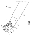
- shaft portions 32 and 34 and 36 have been shown as transparent parts in Figs. 4 through 7 in order to have sight onto inner parts of the endoscope 10.
- the distal head 16 is connected to the first shaft portion 32 in articulated fashion via a pin connection so that the distal head 16 is pivotable about a first pivot axis 38 according to a double arrow 39.
- the first shaft portion 32 in turn is connected to the second shaft portion 34 in articulated manner via another pin connection so that the first shaft portion 34 and thereby the distal head 16 is pivotable about a second pivot axis 40 according to a double arrow 41.
- the optical imaging system 18 is pivotable about the first pivot axis 38 as well as about the second pivot axis 40 according to the double arrows 39 and 41.
- the second pivot axis 40 is spaced from the first pivot axis 38 in direction of the longitudinal axis 13 of the endoscope shaft 12.
- the distance between the first pivot axis 38 and the second pivot axis 40 is approximately equal to or somewhat larger than the outer diameter of the shaft 12 of the endoscope 10.
- the first pivot axis 38 and the second pivot axis 40 both run about transversely to the longitudinal axis 13 of the shaft 12 and are about parallel to one another.
- the optical imaging system 18 is pivotable about the first and second pivot axis 38, 40 in opposite directions with respect to the longitudinal axis 13.
- the pivot axes 38 and 40 allow for a pivoting movement of the optical imaging system 18 in one plane, which is the plane of the drawing in Fig. 1 , over an overall pivot range of ⁇ 180° from the longitudinal axis 13 of the shaft 12.
- the direction of view or the angle of view can be changed from 0° as shown in Fig. 1 , where the direction of view illustrated by line 42 in Fig. 1 coincides with the longitudinal axis 13 of the shaft 12 of the endoscope 10, to both sides of the longitudinal axis 13 by ⁇ 180°.
- An angle of view of 180° with respect to the longitudinal axis 13 of the shaft 12 of the endoscope 10 means a backward view as shown in Fig. 4 .
- the single pivot range of the pivoting movement of the optical imaging system 18 about the first pivot axis 38 and about the second pivot axis 40, respectively, is at least about ⁇ 90°.
- the distal head 16 is pivoted about the first pivot axis 38 by an angle of about 90°
- the first shaft portion 32 is pivoted about the second pivot axis 40 by an angle of about 90°, too, leading to an overall pivot range of about 180°.
- the optical imaging system 18 is pivoted about the first pivot axis 38 and the second pivot axis 40 by an overall angle of about 90° with respect to the longitudinal axis 13 of the shaft 12 of the endoscope 10, wherein the distal head 16 is pivoted about the first pivot axis 38 by an angle of about 45°, and the first shaft portion 32 is pivoted about the second pivot axis 40 by an angle of about 45°, too.
- the same pivot angle of 90° of the optical imaging system 18 with respect to the longitudinal axis 13 can be achieved by pivoting the distal head 16 about the first pivot axis 38 by an angle of about 90°, while the first shaft portion 32 is in its 0° position, i.e. aligned with the second shaft portion 34.
- the distal head 16 is pivotable about the first pivot axis 38 by a maximum angle of about 90°, and the first shaft portion 32 is pivotable about the second pivot axis 40 by a maximum pivot angle of about 90°, too.
- the first and second pivot axis 38 and 40 are conceivable.
- the optical imaging system 18 is not only pivotable in a plane in order to change the direction of view, but is also rotatable with respect to the shaft 12 about the longitudinal axis 13 thereof. This is accomplished by the fact that the second shaft portion 34 is rotatable about the longitudinal axis 13 with respect to the outer shaft 14 of the endoscope 10.
- Rotation of the optical imaging system 18 about the longitudinal axis 13 changes the direction of view in a plane perpendicular to the longitudinal axis 13 (in the 90° case) or the direction of view is swept over a cone the aperture angle of which is determined by the pivot angle of the optical imaging system 18 about the first and second pivot axis 38, 40.
- the maximum rotary angle of the second shaft portion 34 about the longitudinal axis 13 is at least 360°.
- the optical imaging system 18 can be moved by pivoting the distal head 16 about the first and second pivot axis 38, 40 and by rotating the second shaft portion 34 about the longitudinal axis 13 in such a manner that the direction of view can take any arbitrary orientation within the entire solid angle of about 4 ⁇ without the need of replacing, rotating or moving the endoscope 10 from its position.
- the endoscope 10 comprises a control mechanism 44 to control the pivoting movement of the optical imaging system 18 about the first pivot axis 38 and the at least one second pivot axis 40.
- Fig. 5 shows only such parts of the control mechanism which are provided to control the pivoting movement of the optical imaging system 18 about the first pivot axis 38.
- the control mechanism 44 comprises a first gear 46, having a first wheel 48 which is fixed to the first shaft portion 32.
- the first wheel 48 is arranged on the axle or pin forming the second pivot axis 40, such that the first wheel 48 can freely rotate about that pin forming the second pivot axis 40.
- the first wheel 48 is a toothed wheel which meshes with a second wheel 50 which is fixed to the distal head 16.
- the second wheel 50 is arranged concentrically with respect to the first pivot axis 38.
- the second wheel 50 is a toothed wheel, too.
- the second wheel 50 is formed as a circumferentially partial ring which is embedded in the housing 20 of the distal head 16.
- the control mechanism 44 comprises a second gear 52 which is configured as a worm gear which is connected to the first gear 46 by means of a belt 54 in order to drive, i.e. to rotate, the first wheel 48 of the first gear 46.
- the control mechanism 44 further comprises an electric motor to drive the second gear 52 and thereby the first gear 46 in order to pivot the distal head 16 and thereby the optical imaging system 18 about the first pivot axis 38.
- the electric motor 56 which is a step motor, is arranged in the third portion 36 of the shaft 12 of the endoscope 10.
- control mechanism 44 comprises a third gear 58 in order to pivot the first shaft portion 32, thereby the distal head 16 and thereby the optical imaging system 18 about the second pivot axis 40.
- the third gear 58 is configured as a worm gear similar to the second gear 52.
- the third gear 58 is connected to the first shaft portion 32 through a push and pull rod 60 which engages the first shaft portion 32 distally spaced from the second pivot axis 40.
- the control mechanism 44 comprises a second electric motor 62 in order to drive the third gear 58, and, thereby, to pivot the first shaft portion 32 about the second pivot axis 40.
- control mechanism 44 is configured such that it can control the pivoting movement of the optical imaging system 18 about the first pivot axis 38 independently from the pivoting movement about the at least one second pivot axis 40 and vice versa.
- the control mechanism 44 further comprises a fourth gear 64 to control the rotating movement of the second shaft portion 34 with respect to the remainder of the shaft 12, in the present case with respect to the outer shaft 14 of the endoscope 10.
- the fourth gear 64 comprises a first wheel 66 fixed to the third shaft portion 36 and having a toothing on its inner side, which meshes with a second wheel 68, having an outer toothing, accordingly.
- the second wheel 68 is driven by a third electric motor 70, which is a step motor.
- Fig. 7 shows all components of the control mechanism 44 described before in place in the endoscope 10.
- Fig. 9 shows a slightly modified embodiment of the control mechanism 44 for pivoting the distal head 16 about the first pivot axis 38.
- the control mechanism 44 comprises a belt which is fed around the pin of the second pivot axis 40, and which is driven by the second gear 52 and the belt 54.
- Fig. 8 shows the complete distal region of the endoscope 10 where the third shaft portion 36 and all the parts of the control mechanism 44 are surrounded by the outer shaft 14 which extends (not shown) to the proximal end of the endoscope 10.
- the outer shaft 14 is connected with a glass ball which surrounds the distal head 16, the first shaft portion and the second shaft portion 34.
- the glass ball 74 is arranged such that in each orientation of the distal head 16 the direction of view is perpendicular to the surface of the glass ball in order to avoid a displacement of the direction of view due to refraction.
- the glass ball 74 can be replaced by a transparent flexible tube, for example.
Landscapes
- Health & Medical Sciences (AREA)
- Life Sciences & Earth Sciences (AREA)
- Surgery (AREA)
- Physics & Mathematics (AREA)
- Engineering & Computer Science (AREA)
- Optics & Photonics (AREA)
- Biomedical Technology (AREA)
- Veterinary Medicine (AREA)
- Biophysics (AREA)
- Pathology (AREA)
- Radiology & Medical Imaging (AREA)
- Nuclear Medicine, Radiotherapy & Molecular Imaging (AREA)
- Public Health (AREA)
- Heart & Thoracic Surgery (AREA)
- Medical Informatics (AREA)
- Molecular Biology (AREA)
- Animal Behavior & Ethology (AREA)
- General Health & Medical Sciences (AREA)
- Multimedia (AREA)
- Astronomy & Astrophysics (AREA)
- General Physics & Mathematics (AREA)
- Signal Processing (AREA)
- Instruments For Viewing The Inside Of Hollow Bodies (AREA)
- Endoscopes (AREA)
Claims (22)
- Endoscope comprenant une tige rigide allongée (12) et un système d'imagerie optique (18) agencé à une extrémité distale sensiblement rigide de la tige (12) pour recevoir de la lumière d'une zone d'observation, dans lequel le système d'imagerie optique (18) peut pivoter par rapport à la tige (12) autour d'un premier axe d'articulation (38) qui s'étend à peu près transversalement par rapport à un axe longitudinal (13) de la tige (12), dans lequel le système d'imagerie optique (18) est au moins partiellement agencé dans une tête distale (16) qui est montée de manière pivotante sur une première partie de tige rigide (32) de sorte à pouvoir pivoter autour du premier axe d'articulation (38), caractérisé en ce que le système d'imagerie optique (18) peut pivoter par rapport à la tige (12) autour d'au moins un second axe d'articulation (40), qui est espacé par rapport au premier axe d'articulation (38) et s'étend à peu près transversalement par rapport à l'axe longitudinal (13) de la tige (12), en ce qu'une plage d'articulation globale du système d'imagerie optique (18) autour des premier et second axes d'articulation (38, 40) est d'au moins 150° par rapport à l'axe longitudinal (13) de la tige (12), et la première partie de tige (32) est montée de manière pivotante sur une seconde partie de tige rigide (34) de sorte à pouvoir tourner autour du second axe d'articulation (40), et en ce que la tête distale (46) comprend un logement de forme sensiblement sphérique (20), dans lequel le premier axe d'articulation (38) s'étend sensiblement à travers le centre du logement de forme sphérique (20).
- Endoscope selon la revendication 1, caractérisé en ce que la plage d'articulation globale est au moins d'environ 180° par rapport à l'axe longitudinal (13) de la tige (12).
- Endoscope selon la revendication 1 ou 2, caractérisé en ce que le système d'imagerie optique (18) peut pivoter autour du premier et/ou d'au moins un second axe d'articulation (38, 40) par rapport à l'axe longitudinal (13) dans des directions opposées.
- Endoscope selon l'une quelconque des revendications 1 à 3, caractérisé en ce que le système d'imagerie optique (18) peut pivoter autour du premier axe d'articulation (38) dans une plage d'au moins environ 70° à environ 110° et autour du second axe d'articulation (40) dans une plage d'au moins environ 40° à environ 110°.
- Endoscope selon l'une quelconque des revendications 1 à 4, caractérisé en ce que le premier axe d'articulation (38) et l'au moins un second axe d'articulation (40) sont à peu près parallèles l'un par rapport à l'autre.
- Endoscope selon l'une quelconque des revendications 1 à 5, caractérisé en ce que le système d'imagerie optique (18) comprend un appareil de prise de vues électronique (24) et un dispositif optique d'imagerie (22) pour imager un objet qui sera observé sur l'appareil de prise de vues (24), l'appareil de prise de vues (24) et le dispositif optique d'imagerie (22) étant agencés dans la tête distale (16).
- Endoscope selon l'une quelconque des revendications 1 à 6, caractérisé en ce que le système d'imagerie optique (18) peut tourner autour de l'axe longitudinal (13) de la tige (12).
- Endoscope selon la revendication 7, caractérisé en ce que la plage de rotation est d'environ 360°.
- Endoscope selon l'une quelconque des revendications 7 ou 8, caractérisé en ce que la seconde partie de tige (32) peut tourner par rapport à une partie fixe (14) de la tige (12).
- Endoscope selon l'une quelconque des revendications 1 à 9, caractérisé en ce qu'un mécanisme de commande (44) est prévu pour commander le mouvement de pivotement du système d'imagerie optique (18) autour du premier et/ou de l'au moins un second axe d'articulation (38, 40).
- Endoscope selon la revendication 10, caractérisé en ce que le mécanisme de commande (44) est configuré de sorte à pouvoir commander le mouvement de pivotement du système d'imagerie optique (18) autour du premier axe d'articulation (38) indépendamment du mouvement de pivotement autour de l'au moins un second axe d'articulation (40) et vice-versa.
- Endoscope selon la revendication 10 ou 11, caractérisé en ce que le mécanisme de commande (44) comprend au moins un engrenage (46) possédant une première roue (48) qui s'engrène avec une seconde roue (50) fixée sur la tête distale (16).
- Endoscope selon l'une quelconque des revendications 10 à 12, caractérisé en ce que le mécanisme de commande (44) comprend une transmission par courroie (54 ; 72) afin de faire pivoter la tête distale (16) par rapport à la première partie de tige (32).
- Endoscope selon la revendication 12 ou 13, caractérisé en ce que le mécanisme de commande (44) comprend au moins un moteur électrique (56) pour entraîner l'engrenage (46, 52) ou la transmission par courroie (54 ; 72).
- Endoscope selon l'une quelconque des revendications 10 à 14, caractérisé en ce que le mécanisme de commande (44) comprend un engrenage (58) ou une transmission par courroie pour commander le mouvement de pivotement de la première partie de tige (32) par rapport à la seconde partie de tige (34).
- Endoscope selon la revendication 15, caractérisé en ce que le mécanisme de commande (44) comprend au moins un moteur électrique (62) pour entraîner l'engrenage (58) ou la transmission par courroie pour faire pivoter la première partie de tige (32) par rapport à la seconde partie de tige (34).
- Endoscope selon quelconque l'une des revendications 10 à 16, caractérisé en ce que le mécanisme de commande (44) comprend un engrenage (64) pour commander le mouvement de rotation de la seconde partie de tige (34) par rapport à une partie fixe (14) de la tige (12).
- Endoscope selon la revendication 17, caractérisé en ce que le mécanisme de commande (44) comprend au moins un moteur électrique (70) pour entraîner l'engrenage (64) afin de faire tourner la seconde partie de tige (34).
- Endoscope selon la revendication 14, 16 ou 18, caractérisé en ce que le moteur électrique (56, 62, 70) est un moteur pas à pas.
- Endoscope selon l'une quelconque des revendications 1 à 19, caractérisé en ce qu'il comprend en outre un système d'éclairement (28) destiné à transmettre la lumière dans la zone d'observation, le système d'éclairement (28) pouvant tourner autour du premier et d'au moins un second axe d'articulation (38, 40) conjointement avec le système d'imagerie optique (18).
- Endoscope selon la revendication 20, caractérisé en ce que le système d'éclairement (28) comprend une source de lumière possédant au moins une diode électroluminescente (DEL) agencée de manière adjacente au système d'imagerie optique (18).
- Endoscope selon la revendication 20 ou 21, caractérisé en ce que le système d'éclairement (28) comprend une source de lumière configurée sous la forme d'un anneau (30) ou au moins sous la forme d'un anneau partiel entourant ou entourant au moins partiellement une fenêtre d'entrée de lumière (29) du système d'imagerie optique (18).
Priority Applications (3)
| Application Number | Priority Date | Filing Date | Title |
|---|---|---|---|
| EP05018933.1A EP1759629B1 (fr) | 2005-08-31 | 2005-08-31 | Endoscope a direction de visée variable |
| US11/512,548 US7553277B2 (en) | 2005-08-31 | 2006-08-30 | Endoscope with variable direction of view |
| JP2006234012A JP2007075604A (ja) | 2005-08-31 | 2006-08-30 | 視野方向可変式内視鏡 |
Applications Claiming Priority (1)
| Application Number | Priority Date | Filing Date | Title |
|---|---|---|---|
| EP05018933.1A EP1759629B1 (fr) | 2005-08-31 | 2005-08-31 | Endoscope a direction de visée variable |
Publications (2)
| Publication Number | Publication Date |
|---|---|
| EP1759629A1 EP1759629A1 (fr) | 2007-03-07 |
| EP1759629B1 true EP1759629B1 (fr) | 2014-04-02 |
Family
ID=35726048
Family Applications (1)
| Application Number | Title | Priority Date | Filing Date |
|---|---|---|---|
| EP05018933.1A Expired - Lifetime EP1759629B1 (fr) | 2005-08-31 | 2005-08-31 | Endoscope a direction de visée variable |
Country Status (3)
| Country | Link |
|---|---|
| US (1) | US7553277B2 (fr) |
| EP (1) | EP1759629B1 (fr) |
| JP (1) | JP2007075604A (fr) |
Cited By (3)
| Publication number | Priority date | Publication date | Assignee | Title |
|---|---|---|---|---|
| DE202015104679U1 (de) | 2015-09-03 | 2015-09-23 | Imk Automotive Gmbh | Kinematik für ein intrakorporal angetriebenes Instrument eines Endoskops |
| DE102015114742A1 (de) | 2015-09-03 | 2017-03-09 | Imk Automotive Gmbh | Kinematik für ein intrakorporal angetriebenes Instrument eines Endoskops |
| EP4003136A1 (fr) * | 2019-07-23 | 2022-06-01 | National University of Ireland Galway | Outil de visualisation |
Families Citing this family (88)
| Publication number | Priority date | Publication date | Assignee | Title |
|---|---|---|---|---|
| US8599250B2 (en) | 2002-03-12 | 2013-12-03 | Karl Storz Imaging, Inc. | Wireless camera coupling |
| US8194122B2 (en) | 2002-03-12 | 2012-06-05 | Karl Storz Imaging, Inc. | Universal scope reader |
| US8723936B2 (en) | 2002-03-12 | 2014-05-13 | Karl Storz Imaging, Inc. | Wireless camera coupling with rotatable coupling |
| US9510740B2 (en) | 2002-03-12 | 2016-12-06 | Karl Storz Endovision, Inc. | Auto recognition of a shaver blade for medical use |
| US20090023998A1 (en) * | 2007-07-17 | 2009-01-22 | Nitesh Ratnakar | Rear view endoscope sheath |
| US7753843B2 (en) | 2006-05-09 | 2010-07-13 | Boston Scientific Scimed, Inc. | Medical device positioning system |
| US9125552B2 (en) * | 2007-07-31 | 2015-09-08 | Ethicon Endo-Surgery, Inc. | Optical scanning module and means for attaching the module to medical instruments for introducing the module into the anatomy |
| US8105233B2 (en) * | 2007-10-24 | 2012-01-31 | Tarek Ahmed Nabil Abou El Kheir | Endoscopic system and method for therapeutic applications and obtaining 3-dimensional human vision simulated imaging with real dynamic convergence |
| EP2217132B1 (fr) | 2007-11-02 | 2013-05-15 | The Trustees of Columbia University in the City of New York | Dispositif d'imagerie chirurgicale pouvant être introduit dans le corps |
| US8323182B2 (en) * | 2007-12-18 | 2012-12-04 | Manohara Harish M | Endoscope and system and method of operation thereof |
| DE202007017822U1 (de) * | 2007-12-18 | 2008-03-13 | Kummert, Bernhard | Inspektionskamera |
| US8647258B2 (en) | 2008-01-10 | 2014-02-11 | Covidien Lp | Apparatus for endoscopic procedures |
| CN101969858B (zh) | 2008-01-10 | 2013-11-27 | 柯惠Lp公司 | 用于手术装置的成像系统 |
| WO2010028371A1 (fr) * | 2008-09-05 | 2010-03-11 | Zubiate, Brett | Dispositif endoscopique à liaisons multiples avec assemblage distal sphérique |
| JP5161714B2 (ja) * | 2008-09-19 | 2013-03-13 | オリンパスメディカルシステムズ株式会社 | 医療機器 |
| US20120022326A1 (en) * | 2008-12-01 | 2012-01-26 | Stc.Unm | Intubating stylets and systems and methods for intubation |
| EP2194624A1 (fr) * | 2008-12-02 | 2010-06-09 | Swisscom AG | Dispositif d'insertion pour un câble dans un réseau de tuyaux existant |
| FR2947911B1 (fr) | 2009-07-09 | 2011-06-17 | Snecma | Dispositif de controle d'un moteur de turbomachine |
| US9339264B2 (en) * | 2010-10-01 | 2016-05-17 | Cook Medical Technologies Llc | Port access visualization platform |
| EP2498667A4 (fr) * | 2009-11-13 | 2017-12-27 | California Institute of Technology | Endoscope miniature d'imagerie stéréo comprenant une puce d'imagerie unique et de filtres passe-bande multibande conjugués |
| EP2519140B1 (fr) * | 2009-12-31 | 2018-01-24 | Boston Scientific Scimed, Inc. | Sonde jetable pour ablation hydrothermique |
| DE102010028147A1 (de) | 2010-04-23 | 2011-10-27 | Olympus Winter & Ibe Gmbh | Endoskop mit variabler Blickrichtung |
| CN102984992A (zh) * | 2010-05-10 | 2013-03-20 | 纳纳米德有限责任公司 | 用于检查身体腔的内表面或对身体腔的内表面成像的方法和内窥镜装置 |
| US9375139B2 (en) * | 2010-07-29 | 2016-06-28 | Cannuflow, Inc. | Arthroscopic system |
| DE102010034380A1 (de) * | 2010-08-13 | 2012-02-16 | Karl Storz Gmbh & Co. Kg | Gelenkabschnitt eines Endoskopschafts |
| JP2012050487A (ja) * | 2010-08-31 | 2012-03-15 | Konica Minolta Opto Inc | プローブ |
| DE102010040990A1 (de) * | 2010-09-17 | 2012-03-22 | Henke-Sass, Wolf Gmbh | Endoskop mit variabler Blickrichtung |
| DE102010040992A1 (de) * | 2010-09-17 | 2012-03-22 | Henke-Sass, Wolf Gmbh | Endoskop mit variabler Blickrichtung |
| EP2625998A4 (fr) * | 2010-10-05 | 2014-06-18 | Panasonic Corp | Endoscope |
| CN203468565U (zh) | 2011-03-10 | 2014-03-12 | 松下电器产业株式会社 | 内窥镜摄像机及内窥镜装置 |
| JP5838311B2 (ja) * | 2011-03-29 | 2016-01-06 | パナソニックIpマネジメント株式会社 | 内視鏡装置 |
| WO2012146664A1 (fr) * | 2011-04-26 | 2012-11-01 | Otto-Von-Guericke-Universität Magdeburg Medizinische Fakultät | Endoscope |
| US9456735B2 (en) | 2012-09-27 | 2016-10-04 | Shahinian Karnig Hrayr | Multi-angle rear-viewing endoscope and method of operation thereof |
| US9295375B2 (en) | 2012-09-27 | 2016-03-29 | Hrayr Karnig Shahinian | Programmable spectral source and design tool for 3D imaging using complementary bandpass filters |
| EP2574268B1 (fr) | 2011-09-30 | 2017-07-12 | Karl Storz GmbH & Co. KG | Endoscope à direction d'observation réglable |
| WO2013051168A1 (fr) * | 2011-10-03 | 2013-04-11 | Serendipity株式会社 | Dispositif de capture d'image et endoscope rigide |
| WO2013069382A1 (fr) * | 2011-11-09 | 2013-05-16 | オリンパス株式会社 | Endoscope et dispositif d'endoscope |
| CA2796525A1 (fr) * | 2011-12-23 | 2013-06-23 | Covidien Lp | Appareil pour procedures endoscopiques |
| DE102011090132B4 (de) * | 2011-12-29 | 2017-09-14 | Olympus Winter & Ibe Gmbh | Videoendoskop und Videoendoskopsystem |
| EP2638845B1 (fr) * | 2012-03-13 | 2016-01-06 | Panasonic Corporation | Caméra endoscopique |
| US20140066710A1 (en) * | 2012-06-19 | 2014-03-06 | University Of Iowa Research Foundation | Devices and methods for intraoperative control of endoscopic imaging |
| DE102012025102A1 (de) * | 2012-12-20 | 2014-06-26 | avateramedical GmBH | Endoskop mit einem Mehrkamerasystem für die minimal-invasive Chirurgie |
| JP2014184060A (ja) * | 2013-03-25 | 2014-10-02 | Fujikura Ltd | 内視鏡 |
| DE202013104188U1 (de) * | 2013-09-13 | 2013-09-18 | Ipek International Gmbh | Drehmodul für ein Inspektionssystem |
| DE102013110543A1 (de) | 2013-09-24 | 2015-03-26 | Karl Storz Gmbh & Co. Kg | Vorrichtung zum Aufnehmen eines Bildes eines Objektfelds an einem menschlichen oder tierischen Körper |
| WO2015139012A1 (fr) | 2014-03-14 | 2015-09-17 | Hrayr Karnig Shahinian | Système d'endoscope et procédé de fonctionnement associé |
| DE102015204007A1 (de) * | 2015-03-05 | 2016-09-08 | Olympus Winter & Ibe Gmbh | Verfahren und Vorrichtung zur Positionsbestimmung bei einem rotatorischen Elektro-Schritt-Motor |
| WO2016154557A1 (fr) | 2015-03-26 | 2016-09-29 | Universidade De Coimbra | Procédés et systèmes pour chirurgie assistée par ordinateur au moyen d'une vidéo intra-opératoire acquise par une caméra à mouvement libre |
| EP3284252B1 (fr) | 2015-04-13 | 2021-07-21 | Universidade De Coimbra | Procédés et systèmes permettant une caractérisation de caméra en termes de fonction de réponse, de couleur et de vignettage sous un éclairage non uniforme |
| US10517470B2 (en) * | 2016-05-13 | 2019-12-31 | Karl Storz Endovision, Inc. | Optical instrument and articulating image sensing apparatus therefor |
| US20230371789A1 (en) * | 2017-03-09 | 2023-11-23 | Nitesh Ratnakar | Endoscope with self-encased self-illuminating wide-angle panoramic imaging module |
| US10582836B1 (en) * | 2017-03-13 | 2020-03-10 | The Trustees of Dartmouth College and Dartmouth-Hitchcock Clinic | System and method of laryngoscopy surgery and imaging |
| US10796499B2 (en) | 2017-03-14 | 2020-10-06 | Universidade De Coimbra | Systems and methods for 3D registration of curves and surfaces using local differential information |
| FR3066817B1 (fr) * | 2017-05-29 | 2019-08-16 | MCE 5 Development | Dispositif de mesure pour moteur a combustion interne comprenant un detecteur de passage d'une cible et moteur comportant un tel dispositif de mesure |
| JP7175989B2 (ja) * | 2018-04-11 | 2022-11-21 | ボストン サイエンティフィック サイムド,インコーポレイテッド | ワーキングチャネルを延長するためのデバイス |
| CA3103224A1 (fr) | 2018-06-17 | 2019-12-26 | Memic Innovative Surgery Ltd. | Bras articule chirurgical |
| CN112806080A (zh) | 2018-09-26 | 2021-05-14 | 弗劳恩霍夫应用研究促进协会 | 用于管理侧链路资源的方法 |
| US20240349992A1 (en) * | 2019-01-30 | 2024-10-24 | Momentis Surgical Ltd. | Imaging device with elongate arm and pivotable camera |
| US12292564B2 (en) | 2019-04-08 | 2025-05-06 | Activ Surgical, Inc. | Systems and methods for medical imaging |
| CN113950279B (zh) | 2019-04-08 | 2023-04-14 | 艾科缇弗外科公司 | 用于医疗成像的系统和方法 |
| DE102019003378A1 (de) | 2019-05-14 | 2020-11-19 | Karl Storz Se & Co. Kg | Beobachtungsinstrument und Videobildgeberanordnung für ein Beobachtungsinstrument |
| CN110353611A (zh) * | 2019-08-09 | 2019-10-22 | 杭州幕林眼镜有限公司 | 一种基于人体内窥镜检查的装置 |
| CN114599263A (zh) | 2019-08-21 | 2022-06-07 | 艾科缇弗外科公司 | 用于医疗成像的系统和方法 |
| US12167835B2 (en) * | 2019-08-22 | 2024-12-17 | Boston Scientific Scimed, Inc. | Disposable endoscopic device |
| JP2023504725A (ja) | 2019-12-05 | 2023-02-06 | モーメンティス サージカル リミテッド | 外科手術用アームを制御するためのユーザ入力デバイスの向き |
| US12290258B2 (en) * | 2019-12-13 | 2025-05-06 | Dinesh Vyas | Stapler apparatus and methods for use |
| US11136879B2 (en) | 2020-01-31 | 2021-10-05 | Aver Technologies, Inc. | Borescope for drilled shaft inspection |
| IL272830B2 (en) | 2020-02-20 | 2024-08-01 | Momentis Surgical Ltd | Surgical robotic positioning cart |
| WO2021183635A1 (fr) * | 2020-03-10 | 2021-09-16 | Vti Medical, Inc. | Plate-forme d'imagerie multi-angle |
| DE102020115257B3 (de) | 2020-06-09 | 2021-10-07 | Karl Storz Se & Co. Kg | Endoskop mit schwenkbarer Bilderfassungseinrichtung |
| DE102020115258B3 (de) | 2020-06-09 | 2021-09-16 | Karl Storz Se & Co. Kg | Endoskop mit schwenkbarer Bilderfassungseinrichtung |
| EP4196041B1 (fr) * | 2020-08-12 | 2025-09-24 | Orvue Surgical A/S | Caméra chirurgicale |
| US12070196B2 (en) | 2020-11-23 | 2024-08-27 | Medos International Sarl | Arthroscopic medical implements and assemblies |
| US20220160220A1 (en) * | 2020-11-23 | 2022-05-26 | Medos International Sárl | Arthroscopic medical implements and assemblies |
| DE102020132776A1 (de) | 2020-12-09 | 2022-06-09 | Karl Storz Se & Co. Kg | Hybridendoskop mit Rotationstrommel für sterile medizinische Anwendungen |
| DE102020132778A1 (de) | 2020-12-09 | 2022-06-09 | Karl Storz Se & Co. Kg | Endoskop mit Rotationstrommel sowie Bedienverfahren |
| US20240423461A1 (en) * | 2021-01-25 | 2024-12-26 | Tympany Medical Limited | Medical instruments |
| EP4032457B1 (fr) * | 2021-01-25 | 2025-07-02 | Tympany Medical Limited | Instruments médicaux |
| CN117279557A (zh) * | 2021-01-25 | 2023-12-22 | 帝帕尼医疗有限公司 | 医疗器械 |
| JP2024532291A (ja) * | 2021-08-24 | 2024-09-05 | モーメンティス サージカル リミテッド | 細長いアーム及び枢動可能なカメラを備えた撮像装置 |
| EP4440480A4 (fr) | 2021-11-30 | 2026-01-21 | Endoquest Robotics Inc | Agencements de dispositifs de commande pour systèmes chirurgicaux robotiques |
| TWI835436B (zh) | 2021-11-30 | 2024-03-11 | 美商安督奎斯特機器人公司 | 用於機器人手術系統的可轉向套管組件、其控制組件及其方法 |
| TWI836752B (zh) | 2021-11-30 | 2024-03-21 | 美商安督奎斯特機器人公司 | 用於機器人控制醫療裝置的力傳輸系統 |
| KR20260041932A (ko) | 2021-11-30 | 2026-03-27 | 엔도퀘스트 로보틱스 인코포레이티드 | 일회용 엔드 이펙터 |
| WO2023182972A1 (fr) * | 2022-03-21 | 2023-09-28 | Karl Storz Endovision, Inc. | Instrument optique avec appareil de détection d'image articulée et canal de travail |
| CN116115174B (zh) * | 2023-01-10 | 2026-03-06 | 苏州欧畅医疗科技有限公司 | 一种可调视角的电子关节镜 |
| DE102023123953B3 (de) | 2023-09-06 | 2024-10-24 | Karl Storz Se & Co. Kg | Endoskop mit einem starren oder flexiblen Schaftrohr |
| US20260067553A1 (en) * | 2024-09-03 | 2026-03-05 | Med Smart Hub Ltd. | Imaging assembly with multiple degrees of movement |
Family Cites Families (28)
| Publication number | Priority date | Publication date | Assignee | Title |
|---|---|---|---|---|
| US3557780A (en) * | 1967-04-20 | 1971-01-26 | Olympus Optical Co | Mechanism for controlling flexure of endoscope |
| JPS6084524A (ja) * | 1983-10-17 | 1985-05-13 | Olympus Optical Co Ltd | 内視鏡 |
| US4832473A (en) * | 1987-02-06 | 1989-05-23 | Olympus Optical Co., Ltd. | Endoscope with elastic actuator comprising a synthetic rubber tube with only radial expansion controlled by a mesh-like tube |
| JPH0740088B2 (ja) * | 1987-02-06 | 1995-05-01 | オリンパス光学工業株式会社 | 内視鏡 |
| US4855838A (en) * | 1988-05-27 | 1989-08-08 | Cues, Inc. | Remotely controlled pan and tilt television camera |
| US5179934A (en) | 1990-02-20 | 1993-01-19 | Olympus Optical Co., Ltd. | Endoscope |
| JP2987452B2 (ja) * | 1990-05-17 | 1999-12-06 | オリンパス光学工業株式会社 | 内視鏡 |
| US5512034A (en) * | 1992-11-25 | 1996-04-30 | Finn; Miles A. | Surgical instrument including viewing optics and a ball probe |
| US5617762A (en) * | 1995-03-10 | 1997-04-08 | Kirsch; Jerry | Miniature positioning device |
| EP0792119A4 (fr) | 1995-09-15 | 1999-01-13 | Pinotage Llc Thompson Robert L | Dispositif d'imagerie a usage chirurgical/diagnostique |
| US6428470B1 (en) * | 1995-09-15 | 2002-08-06 | Pinotage, Llc | Imaging system and components thereof |
| US5810716A (en) * | 1996-11-15 | 1998-09-22 | The United States Of America As Represented By The Secretary Of The Navy | Articulated manipulator for minimally invasive surgery (AMMIS) |
| US5757419A (en) * | 1996-12-02 | 1998-05-26 | Qureshi; Iqbal | Inspection method and apparatus for tanks and the like |
| JP3953593B2 (ja) * | 1997-09-08 | 2007-08-08 | オリンパス株式会社 | 内視鏡 |
| US5989182A (en) * | 1997-12-19 | 1999-11-23 | Vista Medical Technologies, Inc. | Device-steering shaft assembly and endoscope |
| US6277064B1 (en) * | 1997-12-30 | 2001-08-21 | Inbae Yoon | Surgical instrument with rotatably mounted offset endoscope |
| AU2775199A (en) | 1998-02-19 | 1999-09-06 | California Institute Of Technology | Apparatus and method for providing spherical viewing during endoscopic procedures |
| DE19839188C2 (de) * | 1998-08-28 | 2003-08-21 | Storz Endoskop Gmbh Schaffhaus | Endoskop |
| US6488619B1 (en) * | 1998-09-08 | 2002-12-03 | Olympus Optical Co., Ltd. | Distal endoscope part having light emitting source such as light emitting diodes as illuminating means |
| JP3765218B2 (ja) | 2000-02-03 | 2006-04-12 | フジノン株式会社 | 内視鏡の操作ワイヤガイド装置 |
| US6393338B1 (en) * | 2000-03-17 | 2002-05-21 | Tadeusz Kemnitz | Apparatus and control method for accurate rotary peristaltic pump filling |
| JP3345645B2 (ja) * | 2000-06-20 | 2002-11-18 | 東京大学長 | 体腔内観察装置 |
| US6916286B2 (en) | 2001-08-09 | 2005-07-12 | Smith & Nephew, Inc. | Endoscope with imaging probe |
| US6648817B2 (en) * | 2001-11-15 | 2003-11-18 | Endactive, Inc. | Apparatus and method for stereo viewing in variable direction-of-view endoscopy |
| FR2838325A1 (fr) | 2002-04-12 | 2003-10-17 | Philippe Benoit | Endoscope |
| WO2004096294A2 (fr) * | 2003-04-28 | 2004-11-11 | Northwestern University | Stylet de visualisation pour intubation endotracheale |
| US8512229B2 (en) * | 2004-04-14 | 2013-08-20 | Usgi Medical Inc. | Method and apparatus for obtaining endoluminal access |
| US7621869B2 (en) * | 2005-05-06 | 2009-11-24 | Nitesh Ratnakar | Next generation colonoscope |
-
2005
- 2005-08-31 EP EP05018933.1A patent/EP1759629B1/fr not_active Expired - Lifetime
-
2006
- 2006-08-30 US US11/512,548 patent/US7553277B2/en not_active Expired - Fee Related
- 2006-08-30 JP JP2006234012A patent/JP2007075604A/ja active Pending
Cited By (4)
| Publication number | Priority date | Publication date | Assignee | Title |
|---|---|---|---|---|
| DE202015104679U1 (de) | 2015-09-03 | 2015-09-23 | Imk Automotive Gmbh | Kinematik für ein intrakorporal angetriebenes Instrument eines Endoskops |
| DE102015114742A1 (de) | 2015-09-03 | 2017-03-09 | Imk Automotive Gmbh | Kinematik für ein intrakorporal angetriebenes Instrument eines Endoskops |
| DE102015114742B4 (de) * | 2015-09-03 | 2017-06-14 | Imk Automotive Gmbh | Kinematik für ein intrakorporal angetriebenes Instrument eines Endoskops |
| EP4003136A1 (fr) * | 2019-07-23 | 2022-06-01 | National University of Ireland Galway | Outil de visualisation |
Also Published As
| Publication number | Publication date |
|---|---|
| US7553277B2 (en) | 2009-06-30 |
| EP1759629A1 (fr) | 2007-03-07 |
| US20070055103A1 (en) | 2007-03-08 |
| JP2007075604A (ja) | 2007-03-29 |
Similar Documents
| Publication | Publication Date | Title |
|---|---|---|
| US7553277B2 (en) | Endoscope with variable direction of view | |
| EP1690492B1 (fr) | Instrument à direction de visée variable avec actionneurs embarqués | |
| EP2147631B1 (fr) | Endoscope à prisme oscillant | |
| US8771177B2 (en) | Wide angle flexible endoscope | |
| US9717398B2 (en) | Lighting system for endoscopic examinations | |
| CN101106932B (zh) | 内窥镜 | |
| US9591962B2 (en) | Endoscope with variable direction of view module | |
| US6371909B1 (en) | Apparatus and method for providing spherical viewing during endoscopic procedures | |
| CA2422525A1 (fr) | Endoscope permettant des vues multiples | |
| US20220133130A1 (en) | Endoscope having distal pivot mechanism and fine adjustment | |
| WO2003013349A2 (fr) | Endoscope dote d'une sonde d'imagerie | |
| US12285162B2 (en) | Systems and methods for robotic endoluminal suturing instrument | |
| US12611092B2 (en) | Systems and methods for configurable endoscope bending section | |
| CN115348831A (zh) | 模块化内窥镜的系统和方法 | |
| US20220240755A1 (en) | Push button mechanism for endoscope, and endoscope | |
| US12167835B2 (en) | Disposable endoscopic device | |
| CN214157257U (zh) | 内窥镜 | |
| EP2617349B1 (fr) | Endoscope souple grand angle | |
| US11931005B2 (en) | Driving force transmission mechanism for endoscope and endoscope | |
| WO2026072539A1 (fr) | Systèmes et procédés pour section de courbure d'instrument articulable | |
| HK40080155A (en) | Systems and methods for modular endoscope |
Legal Events
| Date | Code | Title | Description |
|---|---|---|---|
| PUAI | Public reference made under article 153(3) epc to a published international application that has entered the european phase |
Free format text: ORIGINAL CODE: 0009012 |
|
| AK | Designated contracting states |
Kind code of ref document: A1 Designated state(s): AT BE BG CH CY CZ DE DK EE ES FI FR GB GR HU IE IS IT LI LT LU LV MC NL PL PT RO SE SI SK TR |
|
| AX | Request for extension of the european patent |
Extension state: AL BA HR MK YU |
|
| 17P | Request for examination filed |
Effective date: 20070905 |
|
| 17Q | First examination report despatched |
Effective date: 20071005 |
|
| AKX | Designation fees paid |
Designated state(s): DE FR GB IT |
|
| GRAP | Despatch of communication of intention to grant a patent |
Free format text: ORIGINAL CODE: EPIDOSNIGR1 |
|
| INTG | Intention to grant announced |
Effective date: 20130906 |
|
| RIN1 | Information on inventor provided before grant (corrected) |
Inventor name: HOEFIG, SIEGFRIED Inventor name: LEI, FANG |
|
| GRAS | Grant fee paid |
Free format text: ORIGINAL CODE: EPIDOSNIGR3 |
|
| GRAA | (expected) grant |
Free format text: ORIGINAL CODE: 0009210 |
|
| AK | Designated contracting states |
Kind code of ref document: B1 Designated state(s): DE FR GB IT |
|
| REG | Reference to a national code |
Ref country code: GB Ref legal event code: FG4D |
|
| REG | Reference to a national code |
Ref country code: DE Ref legal event code: R081 Ref document number: 602005043144 Country of ref document: DE Owner name: KARL STORZ SE & CO. KG, DE Free format text: FORMER OWNER: KARL STORZ GMBH & CO. KG, 78532 TUTTLINGEN, DE |
|
| REG | Reference to a national code |
Ref country code: DE Ref legal event code: R096 Ref document number: 602005043144 Country of ref document: DE Effective date: 20140515 |
|
| REG | Reference to a national code |
Ref country code: DE Ref legal event code: R097 Ref document number: 602005043144 Country of ref document: DE |
|
| PLBE | No opposition filed within time limit |
Free format text: ORIGINAL CODE: 0009261 |
|
| STAA | Information on the status of an ep patent application or granted ep patent |
Free format text: STATUS: NO OPPOSITION FILED WITHIN TIME LIMIT |
|
| 26N | No opposition filed |
Effective date: 20150106 |
|
| REG | Reference to a national code |
Ref country code: DE Ref legal event code: R097 Ref document number: 602005043144 Country of ref document: DE Effective date: 20150106 |
|
| REG | Reference to a national code |
Ref country code: FR Ref legal event code: PLFP Year of fee payment: 12 |
|
| PGFP | Annual fee paid to national office [announced via postgrant information from national office to epo] |
Ref country code: IT Payment date: 20160722 Year of fee payment: 12 |
|
| REG | Reference to a national code |
Ref country code: FR Ref legal event code: PLFP Year of fee payment: 13 |
|
| REG | Reference to a national code |
Ref country code: DE Ref legal event code: R081 Ref document number: 602005043144 Country of ref document: DE Owner name: KARL STORZ SE & CO. KG INTELLECTUAL PROPERTY, DE Free format text: FORMER OWNER: KARL STORZ GMBH & CO. KG, 78532 TUTTLINGEN, DE Ref country code: DE Ref legal event code: R082 Ref document number: 602005043144 Country of ref document: DE Representative=s name: WITTE, WELLER & PARTNER PATENTANWAELTE MBB, DE Ref country code: DE Ref legal event code: R081 Ref document number: 602005043144 Country of ref document: DE Owner name: KARL STORZ SE & CO. KG, DE Free format text: FORMER OWNER: KARL STORZ GMBH & CO. KG, 78532 TUTTLINGEN, DE |
|
| REG | Reference to a national code |
Ref country code: FR Ref legal event code: PLFP Year of fee payment: 14 |
|
| PG25 | Lapsed in a contracting state [announced via postgrant information from national office to epo] |
Ref country code: IT Free format text: LAPSE BECAUSE OF NON-PAYMENT OF DUE FEES Effective date: 20170831 |
|
| PGFP | Annual fee paid to national office [announced via postgrant information from national office to epo] |
Ref country code: FR Payment date: 20190722 Year of fee payment: 15 |
|
| PGFP | Annual fee paid to national office [announced via postgrant information from national office to epo] |
Ref country code: GB Payment date: 20190722 Year of fee payment: 15 |
|
| PGFP | Annual fee paid to national office [announced via postgrant information from national office to epo] |
Ref country code: DE Payment date: 20200721 Year of fee payment: 16 |
|
| GBPC | Gb: european patent ceased through non-payment of renewal fee |
Effective date: 20200831 |
|
| PG25 | Lapsed in a contracting state [announced via postgrant information from national office to epo] |
Ref country code: FR Free format text: LAPSE BECAUSE OF NON-PAYMENT OF DUE FEES Effective date: 20200831 |
|
| PG25 | Lapsed in a contracting state [announced via postgrant information from national office to epo] |
Ref country code: GB Free format text: LAPSE BECAUSE OF NON-PAYMENT OF DUE FEES Effective date: 20200831 |
|
| REG | Reference to a national code |
Ref country code: DE Ref legal event code: R119 Ref document number: 602005043144 Country of ref document: DE |
|
| PG25 | Lapsed in a contracting state [announced via postgrant information from national office to epo] |
Ref country code: DE Free format text: LAPSE BECAUSE OF NON-PAYMENT OF DUE FEES Effective date: 20220301 |