EP1759804A1 - Machine d'usinage laser comprenant un dispositif de polissage de buse - Google Patents
Machine d'usinage laser comprenant un dispositif de polissage de buse Download PDFInfo
- Publication number
- EP1759804A1 EP1759804A1 EP06405238A EP06405238A EP1759804A1 EP 1759804 A1 EP1759804 A1 EP 1759804A1 EP 06405238 A EP06405238 A EP 06405238A EP 06405238 A EP06405238 A EP 06405238A EP 1759804 A1 EP1759804 A1 EP 1759804A1
- Authority
- EP
- European Patent Office
- Prior art keywords
- nozzle
- axis
- laser processing
- polishing device
- processing
- Prior art date
- Legal status (The legal status is an assumption and is not a legal conclusion. Google has not performed a legal analysis and makes no representation as to the accuracy of the status listed.)
- Granted
Links
Images




Classifications
-
- B—PERFORMING OPERATIONS; TRANSPORTING
- B23—MACHINE TOOLS; METAL-WORKING NOT OTHERWISE PROVIDED FOR
- B23K—SOLDERING OR UNSOLDERING; WELDING; CLADDING OR PLATING BY SOLDERING OR WELDING; CUTTING BY APPLYING HEAT LOCALLY, e.g. FLAME CUTTING; WORKING BY LASER BEAM
- B23K37/00—Auxiliary devices or processes, not specially adapted for a procedure covered by only one of the other main groups of this subclass
- B23K37/04—Auxiliary devices or processes, not specially adapted for a procedure covered by only one of the other main groups of this subclass for holding or positioning work
- B23K37/0408—Auxiliary devices or processes, not specially adapted for a procedure covered by only one of the other main groups of this subclass for holding or positioning work for planar work
-
- B—PERFORMING OPERATIONS; TRANSPORTING
- B23—MACHINE TOOLS; METAL-WORKING NOT OTHERWISE PROVIDED FOR
- B23K—SOLDERING OR UNSOLDERING; WELDING; CLADDING OR PLATING BY SOLDERING OR WELDING; CUTTING BY APPLYING HEAT LOCALLY, e.g. FLAME CUTTING; WORKING BY LASER BEAM
- B23K26/00—Working by laser beam, e.g. welding, cutting or boring
- B23K26/08—Devices involving relative movement between laser beam and workpiece
- B23K26/0869—Devices involving movement of the laser head in at least one axial direction
- B23K26/0876—Devices involving movement of the laser head in at least one axial direction in at least two axial directions
- B23K26/0884—Devices involving movement of the laser head in at least one axial direction in at least two axial directions in at least three axial directions, e.g. manipulators, robots
-
- B—PERFORMING OPERATIONS; TRANSPORTING
- B23—MACHINE TOOLS; METAL-WORKING NOT OTHERWISE PROVIDED FOR
- B23K—SOLDERING OR UNSOLDERING; WELDING; CLADDING OR PLATING BY SOLDERING OR WELDING; CUTTING BY APPLYING HEAT LOCALLY, e.g. FLAME CUTTING; WORKING BY LASER BEAM
- B23K26/00—Working by laser beam, e.g. welding, cutting or boring
- B23K26/14—Working by laser beam, e.g. welding, cutting or boring using a fluid stream, e.g. a jet of gas, in conjunction with the laser beam; Nozzles therefor
- B23K26/1462—Nozzles; Features related to nozzles
- B23K26/1482—Detachable nozzles, e.g. exchangeable or provided with breakaway lines
-
- B—PERFORMING OPERATIONS; TRANSPORTING
- B23—MACHINE TOOLS; METAL-WORKING NOT OTHERWISE PROVIDED FOR
- B23K—SOLDERING OR UNSOLDERING; WELDING; CLADDING OR PLATING BY SOLDERING OR WELDING; CUTTING BY APPLYING HEAT LOCALLY, e.g. FLAME CUTTING; WORKING BY LASER BEAM
- B23K26/00—Working by laser beam, e.g. welding, cutting or boring
- B23K26/14—Working by laser beam, e.g. welding, cutting or boring using a fluid stream, e.g. a jet of gas, in conjunction with the laser beam; Nozzles therefor
- B23K26/1462—Nozzles; Features related to nozzles
- B23K26/1494—Maintenance of nozzles
-
- B—PERFORMING OPERATIONS; TRANSPORTING
- B23—MACHINE TOOLS; METAL-WORKING NOT OTHERWISE PROVIDED FOR
- B23K—SOLDERING OR UNSOLDERING; WELDING; CLADDING OR PLATING BY SOLDERING OR WELDING; CUTTING BY APPLYING HEAT LOCALLY, e.g. FLAME CUTTING; WORKING BY LASER BEAM
- B23K26/00—Working by laser beam, e.g. welding, cutting or boring
- B23K26/70—Auxiliary operations or equipment
- B23K26/702—Auxiliary equipment
-
- B—PERFORMING OPERATIONS; TRANSPORTING
- B23—MACHINE TOOLS; METAL-WORKING NOT OTHERWISE PROVIDED FOR
- B23K—SOLDERING OR UNSOLDERING; WELDING; CLADDING OR PLATING BY SOLDERING OR WELDING; CUTTING BY APPLYING HEAT LOCALLY, e.g. FLAME CUTTING; WORKING BY LASER BEAM
- B23K37/00—Auxiliary devices or processes, not specially adapted for a procedure covered by only one of the other main groups of this subclass
- B23K37/02—Carriages for supporting the welding or cutting element
- B23K37/0211—Carriages for supporting the welding or cutting element travelling on a guide member, e.g. rail, track
- B23K37/0235—Carriages for supporting the welding or cutting element travelling on a guide member, e.g. rail, track the guide member forming part of a portal
-
- B—PERFORMING OPERATIONS; TRANSPORTING
- B24—GRINDING; POLISHING
- B24B—MACHINES, DEVICES, OR PROCESSES FOR GRINDING OR POLISHING; DRESSING OR CONDITIONING OF ABRADING SURFACES; FEEDING OF GRINDING, POLISHING, OR LAPPING AGENTS
- B24B27/00—Other grinding machines or devices
- B24B27/033—Other grinding machines or devices for grinding a surface for cleaning purposes, e.g. for descaling or for grinding off flaws in the surface
-
- B—PERFORMING OPERATIONS; TRANSPORTING
- B24—GRINDING; POLISHING
- B24B—MACHINES, DEVICES, OR PROCESSES FOR GRINDING OR POLISHING; DRESSING OR CONDITIONING OF ABRADING SURFACES; FEEDING OF GRINDING, POLISHING, OR LAPPING AGENTS
- B24B9/00—Machines or devices designed for grinding edges or bevels on work or for removing burrs; Accessories therefor
- B24B9/007—Machines or devices designed for grinding edges or bevels on work or for removing burrs; Accessories therefor for end faces of tubes
Definitions
- the present invention provides means for unattended operation for a long time of period by removing contaminants with a cutting tool such as a grinding tool when contaminants adhere to a nozzle of a laser processing machine.
- Patent Document 1 discloses a machine having a brush for removing dross which adheres to a nozzle.
- some melt (sputtered material) in the processing flies above a work surface, due to the pressure of an assist gas for example, and adheres to a bottom surface of a nozzle, which makes a gap between the bottom surface of the nozzle and the upper work surface non-uniform.
- the patent document above described discloses a copy operation to control the position of a laser processing tool in the Z axis direction which records a Z axis coordinate by bring a nozzle into contact with a touch sensor.
- the patent document also discloses a method for removing contaminants such as dross adhering to a nozzle by bringing a nozzle tip to a brush so that a circular motion of the nozzle removes the contaminants.
- the present invention provides a device having a polishing device to polish a nozzle without moving the nozzle.
- a laser processing machine comprises: a bed; a pallet disposed on the bed to support a work; a column which is controlled to move along the X axis, the X axis being the longitudinal axis of the bed; a saddle which is supported by the column and is controlled to move along the Y axis, the Y axis being perpendicularly crossing the X axis; a processing head which is supported by the saddle and is controlled to move along the Z axis, the Z axis being perpendicular to a plane defined by the X axis and the Y axis.
- the present invention provides a nozzle polishing device comprising a melt removing device for removing melt with a grinding tool, the melt adhering to a tip nozzle of a laser processing tool mounted to the processing head as basic means.
- a copy function is stabilized so that a gap between a bottom surface of a nozzle and an upper work surface becomes uniform, imperfections in a processing such as dross forming are not caused, which stabilizes the processing and makes an unattended operation for a long time of period possible.
- FIG. 1 is a perspective view to generally show a laser processing machine according to the present invention.
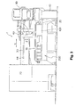
- FIG. 2 is a plan view of the same
- FIG. 3 is an elevational view of the same
- FIG. 4 is a perspective view to show the main parts of the same
- FIG. 5 is a side view to show the main parts of the same.
- a laser processing machine which is generally denoted by reference numeral 1, has a bed 10 and a pallet (table) 20 disposed on the bed 10, and a sheet of a work W 1 is rested on the pallet 20.
- a pallet exchanging device 12 is arranged adjacent to the bed 10 in the longitudinal direction of the bed 10, having a pallet 20a on which a work W 2 is rested for a subsequent processing.
- a pair of guide rails 34 are provided along both of the longitudinal sides of the bed 10, and a column 30 is mounted on the guide rails 34 to be movable in the X axis direction.
- the column 30 may move in the X axis direction driven by for example a linear motor which is formed with a stator provided to the guide rails 34 and movers provided to translation guides 32.
- the column 30 includes a guide rail 44 provided along the Y axis which is perpendicularly crossing the X axis to mount a saddle 40 movable in the Y axis direction.
- the saddle 40 includes a translation guide 42 which engages with the guide rail 44, which forms a linear motor between the guide rail 44 and the translation guide 42.
- the saddle 40 includes a guide rail in the Z axis direction which is perpendicular to a plane defined by the X axis and the Y axis, and a processing head 50 is mounted to the guide rail movable along the Z axis.
- the processing head 50 includes an optical system into which a laser beam is introduced from a laser emitting device 72.
- a laser processing tool 60 is exchangeably mounted to the processing head 50.
- a processing area is covered with a cover 90 for safety.
- An electric cabinet 70 and the laser emitting device 72 are arranged adjacent to the bed 10.
- a control panel 80 through which an operator issues commands for various operations is disposed at one end of a longitudinal side of the bed 10.
- a setup station 100 for a laser processing tool is equipped with.
- FIG. 6 is an elevational view to show the setup station 100 for a laser processing tool as seen from the table
- FIG. 7 is a plan view to show the same.
- the setup station 100 for a laser processing tool includes: a tool station 200 equipped with a tool change magazine for laser processing tools having a torch and a nozzle respectively; and a nozzle station 300 equipped with a nozzle change magazine for nozzles of the laser processing tools.
- FIG. 8 is a view to illustrate a nozzle polishing device according to the present invention.
- a nozzle polishing device 600 includes a processing head 610, and the processing head 610 drives a processing tool 620 which is a formed grindstone.
- the processing tool 620 may be a formed grindstone having a processing surface 622 corresponding to the outer configuration of a nozzle 65.
- a laser processing head equipped with the nozzle 65 to which sputtered material S 1 adheres is positioned above the nozzle polishing device 600, and the entire laser processing tool is lowered in the Z axis direction.
- FIG. 10 is a view to illustrate another example of a nozzle polishing device.
- a nozzle polishing device 650 has a frame 652 and a processing head 660 which is supported with bolts 654 in the frame 652.
- the processing head 660 is equipped with a motor therein, and has a rotation shaft 662 mounted with a cylindrical grindstone 670.
- the cylindrical grindstone 670 has an upper surface 672 which is used to polish and remove contaminants such as dross adhering to a bottom end surface of the nozzle 65.
- FIG. 11 is a view to illustrate another example of a nozzle polishing device according to the present invention.
- a nozzle 65a includes a flange portion 65b, and sputtered material S 1 adhering to the flange portion 65b sometimes causes imperfections in a processing.
- a nozzle polishing device 650 is used so that an upper surface 672 of a cylindrical grindstone 670 is brought into contact with the flange portions 65b of the nozzle 65a to remove the sputtered material S 1 .
- the nozzle polishing device 650 is moved in circle along the flange portions 65b in the direction shown by an arrow R 2 to complete the removal of the sputtered material S 1 .
- a grindstone is used as a polishing tool for a nozzle, but of course, other tools such as a carbide tool may be used as needed.
Landscapes
- Engineering & Computer Science (AREA)
- Physics & Mathematics (AREA)
- Optics & Photonics (AREA)
- Mechanical Engineering (AREA)
- Plasma & Fusion (AREA)
- Robotics (AREA)
- Laser Beam Processing (AREA)
Applications Claiming Priority (1)
| Application Number | Priority Date | Filing Date | Title |
|---|---|---|---|
| JP2005249695A JP2006175580A (ja) | 2004-11-29 | 2005-08-30 | レーザ加工機におけるノズル研磨装置 |
Publications (2)
| Publication Number | Publication Date |
|---|---|
| EP1759804A1 true EP1759804A1 (fr) | 2007-03-07 |
| EP1759804B1 EP1759804B1 (fr) | 2009-11-11 |
Family
ID=37460230
Family Applications (1)
| Application Number | Title | Priority Date | Filing Date |
|---|---|---|---|
| EP06405238A Not-in-force EP1759804B1 (fr) | 2005-08-30 | 2006-05-31 | Machine d'usinage laser comprenant un dispositif de polissage de buse |
Country Status (4)
| Country | Link |
|---|---|
| US (1) | US20070045258A1 (fr) |
| EP (1) | EP1759804B1 (fr) |
| CN (1) | CN100558496C (fr) |
| DE (1) | DE602006010283D1 (fr) |
Cited By (1)
| Publication number | Priority date | Publication date | Assignee | Title |
|---|---|---|---|---|
| US20220379413A1 (en) * | 2019-10-31 | 2022-12-01 | Amada Co., Ltd. | Workpiece support member for use with workpiece support table, and thermal processing machine |
Families Citing this family (4)
| Publication number | Priority date | Publication date | Assignee | Title |
|---|---|---|---|---|
| US20090076741A1 (en) * | 2007-09-19 | 2009-03-19 | Eb Associates, Inc. | Distributed system for measuring lumber in a sawmill |
| DE102013200067A1 (de) * | 2013-01-04 | 2014-07-10 | Ford-Werke Gmbh | Vorrichtung zum thermischen Beschichten einer Oberfläche |
| DE102016209285B3 (de) * | 2016-05-30 | 2017-08-17 | Trumpf Maschinen Ag | Bearbeitungsmaschine mit einem Düsenwechsler |
| USD850500S1 (en) * | 2016-08-31 | 2019-06-04 | Trumpf Gmbh + Co. Kg | Machine tool |
Citations (4)
| Publication number | Priority date | Publication date | Assignee | Title |
|---|---|---|---|---|
| US5091625A (en) * | 1990-02-16 | 1992-02-25 | Brother Kogyo Kabushiki Kaisha | Plasma arc cutting device having metal deposition removal function and method for removing deposition from nozzle of the plasma arc cutting device |
| US5854460A (en) * | 1996-05-07 | 1998-12-29 | Cincinnati Incorporated | Linear motor driven laser cutting machine |
| JP2001150173A (ja) * | 1999-11-22 | 2001-06-05 | Amada Wasino Co Ltd | レーザ加工方法及びその装置 |
| JP2001162376A (ja) * | 1999-12-09 | 2001-06-19 | Koji Irie | 溶接トーチの研磨用具 |
Family Cites Families (7)
| Publication number | Priority date | Publication date | Assignee | Title |
|---|---|---|---|---|
| US4027137A (en) * | 1975-09-17 | 1977-05-31 | International Business Machines Corporation | Laser drilling nozzle |
| US4272007A (en) * | 1979-02-02 | 1981-06-09 | Steranko James J | Wire bonding system and method |
| US4593445A (en) * | 1984-11-13 | 1986-06-10 | Westinghouse Electric Corp. | Apparatus and process for refurbishing valves |
| US5304773A (en) * | 1992-02-19 | 1994-04-19 | Trumpf Inc. | Laser work station with optical sensor for calibration of guidance system |
| JP3057631B2 (ja) * | 1995-11-24 | 2000-07-04 | 株式会社新川 | 被覆ワイヤのワイヤボンディングツールの清浄方法 |
| US6976909B1 (en) * | 2003-05-30 | 2005-12-20 | Hoover Bruce G | Extended sanding support |
| JP4338204B2 (ja) * | 2005-03-30 | 2009-10-07 | Tdk株式会社 | 半田付け方法及び半田付け装置並びに接合方法及び接合装置 |
-
2006
- 2006-05-25 US US11/420,278 patent/US20070045258A1/en not_active Abandoned
- 2006-05-31 DE DE602006010283T patent/DE602006010283D1/de active Active
- 2006-05-31 EP EP06405238A patent/EP1759804B1/fr not_active Not-in-force
- 2006-06-05 CN CNB2006100887646A patent/CN100558496C/zh not_active Expired - Fee Related
Patent Citations (4)
| Publication number | Priority date | Publication date | Assignee | Title |
|---|---|---|---|---|
| US5091625A (en) * | 1990-02-16 | 1992-02-25 | Brother Kogyo Kabushiki Kaisha | Plasma arc cutting device having metal deposition removal function and method for removing deposition from nozzle of the plasma arc cutting device |
| US5854460A (en) * | 1996-05-07 | 1998-12-29 | Cincinnati Incorporated | Linear motor driven laser cutting machine |
| JP2001150173A (ja) * | 1999-11-22 | 2001-06-05 | Amada Wasino Co Ltd | レーザ加工方法及びその装置 |
| JP2001162376A (ja) * | 1999-12-09 | 2001-06-19 | Koji Irie | 溶接トーチの研磨用具 |
Non-Patent Citations (1)
| Title |
|---|
| DATABASE WPI Week 200160, Derwent World Patents Index; AN 2001-539046, XP002410461 * |
Cited By (1)
| Publication number | Priority date | Publication date | Assignee | Title |
|---|---|---|---|---|
| US20220379413A1 (en) * | 2019-10-31 | 2022-12-01 | Amada Co., Ltd. | Workpiece support member for use with workpiece support table, and thermal processing machine |
Also Published As
| Publication number | Publication date |
|---|---|
| US20070045258A1 (en) | 2007-03-01 |
| DE602006010283D1 (de) | 2009-12-24 |
| CN1923428A (zh) | 2007-03-07 |
| EP1759804B1 (fr) | 2009-11-11 |
| CN100558496C (zh) | 2009-11-11 |
Similar Documents
| Publication | Publication Date | Title |
|---|---|---|
| US7159294B2 (en) | Burr removal apparatus for laser beam machine | |
| US6327761B1 (en) | Apparatus for machining a flat metallic workpiece | |
| JP7220035B2 (ja) | 帯鋸盤 | |
| EP1600241B1 (fr) | Dispositif ajusteur focalisation pour une machine à faisceau laser | |
| EP1759804A1 (fr) | Machine d'usinage laser comprenant un dispositif de polissage de buse | |
| TWI475710B (zh) | 製造薄層太陽能電池模組的裝置 | |
| JP5008861B2 (ja) | 搬送装置およびバンドソー型切断装置 | |
| JP2006175580A (ja) | レーザ加工機におけるノズル研磨装置 | |
| JP5170862B2 (ja) | レーザ切断装置 | |
| KR20190125221A (ko) | 스크라이브 장치의 분진 흡인 기구 | |
| JP2004209534A (ja) | レーザ・パンチ複合加工機及びワーク加工屑清掃方法 | |
| CN110561624B (zh) | 一种使用真空同步带的平板材料打孔、磨边、水切割加工设备及加工方法 | |
| JP2891379B2 (ja) | ワーク垂直型レーザーマシン | |
| US4632365A (en) | Apparatus for the torch cutting of a steel structural shape | |
| JP3457370B2 (ja) | レーザ加工機 | |
| JPH05212611A (ja) | 溶接角柱のデポ処理兼用開先加工装置 | |
| CN112059437A (zh) | 一种板管一体机的管材切割方法 | |
| JP2004202533A (ja) | 複合加工機 | |
| CN113815025A (zh) | 卷料裁切装置及激光切割系统 | |
| JP2011136356A (ja) | レーザ加工機 | |
| KR20110040076A (ko) | 플라즈마 커팅 장치 | |
| KR200315263Y1 (ko) | 보이스 코일 모터용 상부요크 스토퍼의 자동 가공장치 | |
| JPH0627230Y2 (ja) | パンチ・レーザ複合加工機 | |
| JP3297540B2 (ja) | 切断機 | |
| JP2749857B2 (ja) | 熱切断複合加工機 |
Legal Events
| Date | Code | Title | Description |
|---|---|---|---|
| PUAI | Public reference made under article 153(3) epc to a published international application that has entered the european phase |
Free format text: ORIGINAL CODE: 0009012 |
|
| AK | Designated contracting states |
Kind code of ref document: A1 Designated state(s): AT BE BG CH CY CZ DE DK EE ES FI FR GB GR HU IE IS IT LI LT LU LV MC NL PL PT RO SE SI SK TR |
|
| AX | Request for extension of the european patent |
Extension state: AL BA HR MK YU |
|
| 17P | Request for examination filed |
Effective date: 20070424 |
|
| 17Q | First examination report despatched |
Effective date: 20070523 |
|
| RAP1 | Party data changed (applicant data changed or rights of an application transferred) |
Owner name: YAMAZAKI MAZAK CORPORATION |
|
| AKX | Designation fees paid |
Designated state(s): DE FR GB IT |
|
| GRAP | Despatch of communication of intention to grant a patent |
Free format text: ORIGINAL CODE: EPIDOSNIGR1 |
|
| GRAS | Grant fee paid |
Free format text: ORIGINAL CODE: EPIDOSNIGR3 |
|
| GRAA | (expected) grant |
Free format text: ORIGINAL CODE: 0009210 |
|
| AK | Designated contracting states |
Kind code of ref document: B1 Designated state(s): DE FR GB IT |
|
| REG | Reference to a national code |
Ref country code: GB Ref legal event code: FG4D |
|
| REF | Corresponds to: |
Ref document number: 602006010283 Country of ref document: DE Date of ref document: 20091224 Kind code of ref document: P |
|
| PLBE | No opposition filed within time limit |
Free format text: ORIGINAL CODE: 0009261 |
|
| STAA | Information on the status of an ep patent application or granted ep patent |
Free format text: STATUS: NO OPPOSITION FILED WITHIN TIME LIMIT |
|
| 26N | No opposition filed |
Effective date: 20100812 |
|
| REG | Reference to a national code |
Ref country code: FR Ref legal event code: PLFP Year of fee payment: 10 |
|
| PGFP | Annual fee paid to national office [announced via postgrant information from national office to epo] |
Ref country code: DE Payment date: 20150527 Year of fee payment: 10 Ref country code: GB Payment date: 20150527 Year of fee payment: 10 |
|
| PGFP | Annual fee paid to national office [announced via postgrant information from national office to epo] |
Ref country code: IT Payment date: 20150515 Year of fee payment: 10 Ref country code: FR Payment date: 20150508 Year of fee payment: 10 |
|
| REG | Reference to a national code |
Ref country code: DE Ref legal event code: R119 Ref document number: 602006010283 Country of ref document: DE |
|
| GBPC | Gb: european patent ceased through non-payment of renewal fee |
Effective date: 20160531 |
|
| PG25 | Lapsed in a contracting state [announced via postgrant information from national office to epo] |
Ref country code: IT Free format text: LAPSE BECAUSE OF NON-PAYMENT OF DUE FEES Effective date: 20160531 |
|
| REG | Reference to a national code |
Ref country code: FR Ref legal event code: ST Effective date: 20170131 |
|
| PG25 | Lapsed in a contracting state [announced via postgrant information from national office to epo] |
Ref country code: FR Free format text: LAPSE BECAUSE OF NON-PAYMENT OF DUE FEES Effective date: 20160531 Ref country code: DE Free format text: LAPSE BECAUSE OF NON-PAYMENT OF DUE FEES Effective date: 20161201 |
|
| PG25 | Lapsed in a contracting state [announced via postgrant information from national office to epo] |
Ref country code: GB Free format text: LAPSE BECAUSE OF NON-PAYMENT OF DUE FEES Effective date: 20160531 |